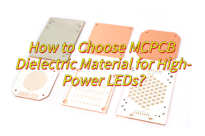
How to choose MCPCB dielectric material for high-power LEDs? This guide covers material functions, types, selection criteria, and design best practices for high-power LED applications.
Are you worried about these issues?
- LED temperature is too high, causing accelerated light decay?
- Uneven thickness of insulation layer causes short circuit risk?
- Is it difficult to control the cost of small batch orders?
EBest Circuit (Best Technology) provide you with:
- Free thermal analysis report: Dielectric layer thermal optimization plan is issued within 48 hours
- Full process quality control: third-party test data is provided for each batch (including thermal conductivity/voltage resistance test)
- Customized formula: adjust dielectric layer parameters according to power density (0.5-4.0W/m·K optional)
Welcome to contact us if you have any inquiry for MCPCB: sales@bestpcbs.com.
What Is MCPCB Dielectric Material?
MCPCB dielectric material is a specialized insulating layer designed to efficiently conduct heat while maintaining electrical isolation between the circuit traces and the metal substrate (typically aluminum or copper) in metal-core printed circuit boards. Unlike traditional FR-4 laminates, this material exhibits significantly higher thermal conductivity (typically 1â3 W/m·K), making it essential for high-power electronic applications where heat dissipation is critical.
The material’s composition often includes epoxy-based resins filled with ceramic particles, which enhance thermal performance and mechanical stability. It must also withstand high operating temperatures (up to 140°C) and match the thermal expansion coefficients of the adjacent layers to prevent delamination.

What Are Functions of MCPCB Dielectric Materials?
- Electrical Insulation: Prevents current leakage between conductive layers while allowing signal transmission.
- Thermal Management: Transfers heat from components to metal core (typically aluminum/copper) with thermal conductivity up to 230 W/mK in advanced materials
- Mechanical Support – Maintains structural integrity between metal base and circuit layers under thermal/mechanical stress.
- Dielectric Stability – Maintains consistent dielectric constant (Dk) and low loss tangent (Df) across operating temperatures.
- Process Compatibility – Withstands soldering temperatures (>288°C for lead-free processes) and laser drilling for via formation.
- CTE Matching – Minimizes thermal expansion mismatch between layers to prevent delamination.

What Are Applications of MCPCB Dielectric Materials?
Applications of MCPCB dielectric materials:
- LED Lighting – Architectural/automotive/industrial high-power LED modules.
- Automotive Systems – ADAS radar modules, EV battery management.
- Power Electronics – DC-DC converters, high-current switching supplies.
- Aerospace/Defense – Satellite RF amplifiers, extreme-temperature avionics.
- AI/HPC Hardware – 2.5D/3D IC packaging for AI accelerators.
- Motor Drives – Industrial VFDs, servo controller IGBT modules.

MCPCB Dielectric Material Dielectric Constant
| Material Type | Dielectric Constant (εr) |
| Ceramic-filled Polymer | 4.0-5.0 |
| Epoxy Resin | 3.5-4.5 |
| Polyimide | 3.2-3.8 |
| AlâOâ-filled Composite | 4.2-4.8 |
| AlN-filled Composite | 8.5-9.5 |
| PTFE | 2.0-2.1 |
What Are Types of MCPCB Dielectric Material?
1. Ceramic-filled Polymer
- Specialty blends with ceramic particles for thermal conductivity (1.0-3.0 W/m·K).
- Used in Bergquist IMS series for LED/automotive applications.
2. Epoxy Resin
- Standard dielectric material with low thermal conductivity (0.3-0.8 W/m·K).
- Cost-effective for low-power MCPCBs.
3. Polyimide
- High-temperature-resistant polymer (up to 260°C).
- Used in aerospace/defense MCPCBs requiring thermal stability.
4. AlâOâ-filled Composite
- Oxide ceramic filler enhances thermal performance (3.5-5.0 W/m·K).
- Common in Dow/Laird high-reliability products.
5. AlN-filled Composite
- Ultra-high thermal conductivity (170-230 W/m·K).
- Premium option for EV battery/RF power modules.
6. PTFE (Polytetrafluoroethylene)
- Low-loss dielectric for high-frequency applications.
- Used in RF/microwave MCPCB designs.
How to Choose MCPCB Dielectric Material for High-Power LEDs?
1. Core Performance Priorities
Thermal Conductivity
- Select â¥2.0 W/m·K materials (e.g., AlN composites) for LED arrays >50W/cm².
- Avoid epoxy resins (<1.0 W/m·K) in high-power applications.
- Verify via ASTM D5470 thermal impedance testing.
Electrical Insulation
- Require breakdown voltage â¥5kV and volume resistivity â¥10¹²Ω·cm.
- Mandate UL 94 V-0 flammability certification.
- Validate performance at 85â/85%RH humidity.
CTE Matching
- Align dielectric CTE with copper (17-18ppm/â) and aluminum (23-24ppm/â).
- Use AlâOâ (6-8ppm/â) with buffer layers for CTE mismatch compensation.
2. Material Selection Strategy
Power Density <3W/cm² (General Lighting)
- Aluminum MCPCB (1.5-2.0W/m·K) with prepreg thickness 0.1-0.2mm.
- Cost-optimized FR-4 alternative with additional heat sinks.
Power Density 3-10W/cm² (Automotive/Industrial)
- Copper MCPCB (3.0-4.5W/m·K) + AlN dielectric layer.
- Require vacuum lamination process with >95% void-free rate.
Power Density >10W/cm² (Laser/UV LEDs)
- DBC ceramic substrate (AlN/BeO) with MIL-STD-883 thermal shock compliance.
- Partner with suppliers providing original sintering curves.
3. Supplier Evaluation Checklist
Technical Compliance
- Provide dielectric thickness vs. thermal resistance curves.
- Share third-party test reports for RoHS/REACH compliance.
Production Capability
- Confirm brown oxidation process uses chromium-free formulas.
- Validate line width accuracy ±10μm and solder mask 288â resistance.
Cost Structure
- Request material cost breakdown (copper 35%/dielectric 40%).
- Negotiate copper price adjustment clauses for ±5% fluctuations.

High-Power LED MCPCB Design Guideline
1. Requirement Analysis
- Define LED power density (W/cm²), operating voltage, and thermal budget.
- Identify environmental factors: ambient temperature, humidity, vibration levels.
- Set cost targets: balance material quality with production volume.
2. Material Selection Strategy
- Low Power (<3W/cm²): Aluminum MCPCB with 1.5-2.0W/m·K dielectric.
- Medium Power (3-10W/cm²): Copper MCPCB + AlN dielectric layer.
- High Power (>10W/cm²): DBC ceramic substrate (AlN/BeO).
3. Layout Optimization
- Place LEDs in matrix pattern with â¥2mm spacing between high-power components.
- Use dedicated traces for power/ground (â¥1mm width for >2A currents).
- Avoid sharp angles in copper traces to prevent hotspots.
4. Thermal Management
- Implement thermal vias under LED pads (diameter â¥0.5mm, pitch â¤1.5mm).
- Use graphite sheets for lateral heat spreading in compact designs.
- Validate thermal performance with IR camera testing.
5. Prototype Validation
- Conduct 72-hour burn-in test at 85â ambient temperature.
- Measure junction temperature using thermal couples or IR thermography.
- Verify insulation resistance after 168hrs at 85%RH humidity.
6. Production Readiness
- Require suppliers to provide PPAP documentation for critical materials.
- Implement SPC for dielectric layer thickness (±10% tolerance).
- Use AOI systems for solder paste inspection and component alignment.
Why Choose EBest Circuit (Best Technology) as MCPCB Manufacturer?
Reasons why choose us as your MCPCB manufacturer:
- High-Quality Dielectric Material Solution – Provides a high-performance insulating layer with a thermal conductivity of 2.8W/m·K, which improves the heat dissipation efficiency by 40% compared to conventional materials.
- 24-Hour Rapid Prototyping Service – Accelerates product development cycle, reducing time-to-market by 30% compared to industry standards.
- Fast Lead Times (7-15 days for bulk orders) â Shorten production cycles by 30% compared to competitors.
- 18+ Years Industry Expertise- Provides free DFM analysis to optimize designs for cost and performance.
- Competitive Pricing with No Hidden Fees – Delivers 15â20% cost savings compared to European suppliers.
- No-MOQ Flexibility â Start with small batches to test markets before scaling up.
- Global Logistics Support â Hassle-free shipping to 50+ countries with customs expertise.
- One-Stop Solution â From PCB design to assembly, reduce supplier management complexity.
- 24/7 Technical Support â Engineers on standby to resolve issues within 4 hours.
- Long-Term Partnership Pricing â Volume discounts and flexible payment terms for repeat clients.
By integrating rapid response with professional technical services, we help customers achieve the core value of reducing R&D cycle by 50%+ and improving mass production yield to 99%, please feel free to contact EBest Circuit (Best Technology) if you have any request for MCPCB: sales@bestpcbs.com.


