

Want precision lighting control? LED controller PCB deliver automotive-grade PWM dimming, RGB spectrum mixing, and thermal-optimized assemblies.
EBest Circuit (Best Technology) stands as your trusted partner for LED PCBA control and custom PCB assembly, delivering precision and efficiency at every step. Our state-of-the-art SMT automated production line ensures high-precision component placement, guaranteeing consistent quality for even the most complex PCB designs. Backed by a robust electronics supply chain, we secure reliable material sourcing to prevent production delays. Recognizing the urgency of prototyping, we offer 24-hour rapid sample turnaround without compromising on accuracy. Whether for small-batch prototyping or mass production, our streamlined processes enable fast lead times to meet your tight schedules. With rigorous quality control at each manufacturing stage, we maintain IPC Class 2/3 standards while achieving cost-effectiveness. Our engineering team provides DFM analysis to optimize your designs for manufacturability before production begins. For LED drivers, control modules or customized PCB solutions, we combine technical expertise with responsive service to bring your concepts to market faster. Contact our specialists today for a competitive quotation tailored to your project specifications.
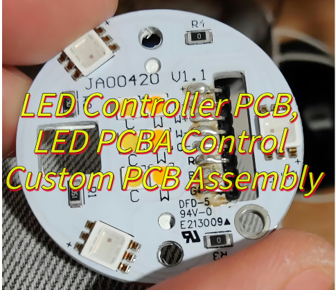
What Is LED Controller PCB?
A LED controller PCB is a specialized printed circuit board designed to precisely regulate power distribution and signal transmission for lighting systems. As the brain of LED operations, the LED Controller PCB integrates microcontrollers, drivers, and sensors to manage brightness, color transitions, and dynamic effects in applications ranging from architectural lighting to automotive displays. Advanced iterations of the LED Controller PCB often incorporate PWM dimming and thermal protection circuits to ensure stable performance under varying loads. By embedding protocols like DMX512 or DALI, the LED Controller PCB enables seamless integration with smart control ecosystems. Customized LED Controller PCB designs may also feature compact layouts for space-constrained installations such as wearable tech or IoT devices. Engineers rely on the LED Controller PCB to balance energy efficiency with optical precision, making it indispensable in modern illumination solutions.
What Are Benefits of LED Controller PCB?
Benefits of LED controller PCB:
- Enhanced Energy Efficiency– LED Controller PCBs optimize power consumption by regulating current flow precisely, ensuring minimal energy waste. This targeted control reduces heat generation and extends the lifespan of LED components, making them ideal for sustainable lighting solutions.
- Improved Performance Consistency– By integrating advanced circuits, LED Controller PCBs maintain stable voltage and current output, preventing flickering or color inconsistencies. This reliability is critical for applications like architectural lighting or displays where visual quality matters most.
- Customizable Lighting Effects– LED Controller PCBs enable dynamic adjustments to brightness, color temperature, and patterns through programmable interfaces. This flexibility allows users to create adaptive environments, such as mood lighting in smart homes or synchronized effects in entertainment venues.
- Cost-Effective Long-Term Investment – While initial setup costs may vary, LED Controller PCBs reduce maintenance expenses by minimizing component failure rates. Their durability ensures fewer replacements, offering a lower total cost of ownership compared to traditional lighting systems.
- Compact Design for Space Optimization – Modern LED Controller PCBs feature compact layouts with high-density component placement, making them suitable for space-constrained installations. This advantage is invaluable in automotive lighting, consumer electronics, and wearable devices.
- Seamless Integration with Smart Systems – LED Controller PCBs support IoT and automation protocols, enabling remote management via apps or sensors. This compatibility enhances user convenience, from smart office lighting that adapts to occupancy to agricultural systems using light spectrum control for plant growth.

How Does RGB LED Controller PCB Achieve Full Spectrum Color Mixing?
Below are how RGB LED controller PCB achieve full spectrum color mixing:
- Precision Current Regulation: Full spectrum color mixing is achieved by independently regulating current to red, green, and blue (RGB) LEDs. By adjusting the intensity of each channel with high-resolution drivers, smooth transitions between hues are ensured, enabling millions of color combinations.
- Pulse Width Modulation (PWM) Control: PWM is used to rapidly toggle LEDs on and off at varying duty cycles. This technique simulates variable brightness levels without changing voltage, ensuring consistent color accuracy even at low intensities.
- Color Space Mapping: Advanced algorithms convert user inputs (e.g., RGB values or color temperatures) into precise voltage/current outputs. This mapping ensures faithful color reproduction across the CIE 1931 color space.
- Thermal Management Integration: Overheating can shift LED wavelength outputs, causing color inconsistencies. Thermal sensors and dynamic compensation circuits adjust drive currents in real time, maintaining color stability even during prolonged use.
- Gamma Correction: Gamma correction compensates for human visual perception nonlinearity, ensuring mid-tone colors appear proportionally brighter and enhancing vivid gradient rendering.
- Synchronization for Multi-Zone Systems: In large installations, multiple units sync via protocols like DMX or SPI. This coordination ensures uniform color mixing across all connected fixtures, ideal for architectural lighting or video walls.
What Makes 3W PWM LED Control PCB Ideal for Automotive Lighting Solutions?
- Robust Thermal Management: The 3W PWM LED Controller PCB integrates advanced heat dissipation designs, such as thick copper traces and thermal vias, to withstand extreme automotive temperature fluctuations (-40°C to 125°C). This ensures the LED Controller PCB maintains stable performance in engine bays or under direct sunlight, preventing overheating-induced failures.
- High-Efficiency Power Conversion: By optimizing PWM duty cycles, the LED Controller PCB minimizes energy waste, making it ideal for electric vehicles (EVs) where battery life is critical. Its 3W power rating balances brightness with low current draw, reducing strain on automotive electrical systems while delivering vivid illumination for headlights or dashboards.
- Vibration and Shock Resistance: Automotive environments expose components to constant vibrations. The LED Controller PCB uses rigid FR-4 substrates and solder mask coatings to resist cracking, ensuring reliable operation even on rough terrains. This durability extends the lifespan of LED modules in applications like brake lights or puddle lamps.
- Precision Dimming for Safety Compliance: The PWM-based LED Controller PCB enables smooth, flicker-free dimming (0.1% resolution), meeting automotive safety standards for daytime running lights (DRLs) and adaptive headlights. This granular control helps drivers adjust visibility without causing distractions, enhancing road safety.
- Compact Form Factor for Space-Constrained Designs: Modern vehicles prioritize lightweight, compact components. The 3W LED Controller PCB’s miniaturized footprint allows integration into tight spaces, such as door handles or interior trim panels, without compromising performance. Its surface-mount design simplifies assembly in automated manufacturing lines.
- EMI/RFI Shielding for Reliable Communication: Automotive networks rely on CAN bus or LIN protocols that are sensitive to electromagnetic interference. The LED Controller PCB incorporates EMI filters and shielded inductors to suppress noise, ensuring stable communication between lighting modules and vehicle control units (VCUs). This compliance with CISPR 25 standards prevents malfunctions in critical systems.
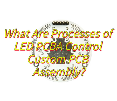
What Are Processes of LED PCBA Control Custom PCB Assembly?
- Design Verification and Schematic Review
The process begins with rigorous design verification for the LED Controller PCB, where engineers use simulation tools to validate signal integrity, power distribution, and thermal management. This step ensures the LED Controller PCB’s layout aligns with functional requirements, such as PWM signal accuracy for dimming or color mixing. - Component Sourcing and BOM Optimization
A bill of materials (BOM) is finalized for the LED Controller PCB, prioritizing high-reliability components like automotive-grade capacitors or industrial-grade microcontrollers. Manufacturers collaborate with certified suppliers to source LED drivers, MOSFETs, and connectors that meet the LED Controller PCB’s voltage and current specifications. - PCB Layout and Thermal Design
Engineers optimize the LED Controller PCB layout using EDA software, balancing trace routing for minimal electromagnetic interference (EMI) and placing thermal vias under power components. For high-power LED Controller PCB designs, copper pours and aluminum substrates are incorporated to dissipate heat from LED drivers. - Automated PCB Fabrication
The LED Controller PCB undergoes automated fabrication, including laser drilling for microvias, laminating with high-TG FR-4 material, and immersion gold finishing to protect against corrosion. This precision ensures the LED Controller PCB meets automotive or aerospace standards for durability. - Surface Mount Technology (SMT) Assembly
Using high-speed pick-and-place machines, components like 0201-sized resistors or QFN LED drivers are mounted on the LED Controller PCB. Reflow ovens with nitrogen atmospheres solder these parts, ensuring void-free joints critical for the LED Controller PCB’s long-term reliability. - Through-Hole Technology (THT) Insertion
Larger components, such as screw terminals or D-sub connectors, are inserted into the LED Controller PCB via automated THT lines. Selective soldering machines apply molten solder to these joints, avoiding heat damage to sensitive SMT parts on the LED Controller PCB. - Automated Optical Inspection (AOI) and Testing
AOI systems scan the LED Controller PCB for defects like solder bridges or missing components. Functional tests, including continuity checks and LED driver output validation, confirm the LED Controller PCB meets specifications for current regulation and PWM frequency. - Conformal Coating and Potting
For harsh-environment applications, the LED Controller PCB is coated with acrylic or silicone conformal coatings to resist moisture, dust, and vibrations. Potting compounds may encapsulate the entire LED Controller PCB for underwater or high-shock use cases. - End-of-Line Functional Testing
Final tests simulate real-world conditions for the LED Controller PCB, such as voltage transient spikes or thermal cycling from -40°C to 85°C. Data loggers verify the LED Controller PCB maintains stable LED current control and communication protocols (e.g., CAN bus, DALI). - Packaging and Traceability
The LED Controller PCB is packaged in ESD-safe bags with desiccants to prevent moisture damage. Serial numbers and lot codes are laser-etched onto the board for traceability, ensuring quality accountability throughout the LED Controller PCB’s lifecycle.
What Advanced Testing Protocols We Apply for Small LED Twinkle Controller PCBA?
Here are testing protocols we supply for small LED twinkle controller PCBA:
- Accelerated Thermal Cycling with Real-Time PWM Monitoring: The LED Controller PCB undergoes extreme temperature cycling (-40°C to 125°C) while operating at full PWM load (e.g., 20kHz for flicker-free dimming). Thermal chambers with integrated oscilloscopes track voltage ripple and current stability across 1,000 cycles, ensuring solder joints and capacitor ESR remain within specs for the LED Controller PCB’s target lifespan (e.g., 50,000 hours for automotive DRLs).
- High-Speed Signal Integrity Testing: For the LED Controller PCB, TDR (Time-Domain Reflectometry) analyzes impedance discontinuities on PWM traces (e.g., 50Ω differential pairs). BERT (Bit Error Rate Testers) validate CAN/LIN communication links at 2+ Mbps, critical for automotive LED Controller PCB networks where bus errors could disable safety features like adaptive headlights.
- EMI/EMC Pre-Compliance Sweep: The LED Controller PCB is tested in a 3m anechoic chamber using spectrum analyzers (9kHz–40GHz) to measure radiated emissions. Engineers apply LISN (Line Impedance Stabilization Networks) to quantify conducted noise, ensuring compliance with CISPR 25 Class 5 for automotive LED Controller PCB modules. Ferrite beads and shielding tweaks are validated in situ to suppress switch-mode power supply noise.
- In-Circuit Current Profiling: A source measure unit (SMU) injects controlled currents (0–5A) into the LED Controller PCB’s LED driver channels while monitoring forward voltage (VF) drift. This identifies weak solder joints or degraded MOSFETs in micro LED arrays, critical for miniature LED Controller PCB designs (e.g., 2mm² PCBs in smartwatch backlights).
- Vibration-Induced Failure Simulation: The LED Controller PCB is mounted on a shaker table (20–2,000Hz, 20G RMS) with laser Doppler vibrometers tracking component deflection. This accelerates fatigue testing for solder joints and connectors, ensuring reliability in applications like motorcycle LED Controller PCB tail lights exposed to constant vibration.
- Humidity-Bias Life Testing (HBLT): For outdoor LED Controller PCB applications (e.g., garden twinkle lights), HBLT chambers apply 85°C/85% RH bias for 1,000 hours. Engineers use LCR meters to monitor capacitor capacitance shift (>5% failure threshold) and optical sensors to detect LED lumen degradation, ensuring the LED Controller PCB meets IP67 waterproof ratings.
- Automated Optical Inspection (AOI) with AI Defect Classification: Advanced AOI systems with 24MP cameras and machine learning algorithms detect solder paste voids, tombstoned 0201 resistors, or lifted QFN pads on the LED Controller PCB. AI models trained on >10,000 images achieve 99.7% accuracy, reducing false positives by 40% compared to traditional rule-based AOI.
- Boundary Scan (JTAG) for Embedded Testing: For LED Controller PCB designs with BGA-mounted microcontrollers, JTAG boundary scan tests verify connectivity between the MCU and peripheral ICs (e.g., LED drivers, MOSFETs). This detects open/short circuits beneath BGA balls without physical probing, critical for 4-layer LED Controller PCB designs with 0.4mm pitch components.
- Power-Up Surge Testing: The LED Controller PCB is subjected to 48V input surges (per ISO 7637-2 Pulse 5a) to validate transient voltage suppressor (TVS) diode response. Oscilloscopes capture clamp voltages across the LED Controller PCB’s power rails, ensuring protection circuits limit surges to safe levels (e.g., <60V for 12V-rated components).
- Micro-sectioning for Process Validation: Cross-sectioned LED Controller PCB samples undergo SEM/EDS analysis to validate plating thickness (e.g., 25µm copper), via fill quality, and laminate adhesion. This microscale inspection ensures compliance with IPC-6012 Class 3 requirements for high-reliability LED Controller PCB applications (e.g., aerospace LED indicators).

How to Reduce Assembly Cost of LED PCBA Control Custom PCB?
Here are ways to reduce assembly cost of LED PCBA control custom PCB:
- Design for Manufacturability (DFM) Simplification: Streamline PCB layouts by minimizing layer counts (e.g., using 2-layer boards instead of 4-layer) and reducing via complexity. Standardize component footprints (e.g., 0805 passives) to avoid custom stencils and assembly tools. Panelize boards efficiently—maximizing units per panel (e.g., 15+ boards on a 18×24” panel) reduces setup costs by 25–35%.
- Component Rationalization and Bulk Purchasing: Replace low-volume or obsolete parts with mainstream alternatives (e.g., using SOT-23 MOSFETs instead of DFN packages). Consolidate suppliers for passive components to secure volume discounts—bulk buying 0603 resistors can cut costs by 40–50%. Prioritize AEC-Q200-qualified parts to avoid retesting for automotive/industrial compliance.
- Automated Assembly with Fiducial Optimization: Implement machine-readable fiducial markers and maintain ≥0.2mm spacing between components to boost pick-and-place machine speed. For LED PCBAs, this reduces assembly time by 15–20% compared to manual soldering. Avoid 0402/0201 passives unless critical, as smaller parts increase placement errors and rework costs.
- Selective Soldering for Mixed-Technology Boards: Use selective soldering instead of wave soldering for boards with both SMT and THT components. This minimizes thermal stress on SMT parts (e.g., MLCC capacitors) and reduces skillet maintenance costs. Nitrogen-purged selective soldering improves joint quality, cutting rework rates by 25%.
- Localized Conformal Coating: Apply conformal coating only to critical areas (e.g., power regulators, connectors) instead of full-board spraying. Mask non-critical zones with polyimide tape to reduce material waste by 40–60%. This maintains protection against moisture (e.g., 85% RH resistance) while shortening coating cycles.
- In-House Basic Testing vs. Outsourced Calibration: For low-to-medium volume runs, invest in basic ATE (Automated Test Equipment) for continuity/power-up tests. Outsource complex calibration (e.g., LED current regulation) to third-party labs only for final validation. This balances CAPEX/OPEX—a 15kin−housetestercanreplace50/hour outsourced services for <5,000 units/year.
- JIT Inventory with Safety Stock Buffer: Implement JIT (Just-In-Time) delivery for components with >12-week lead times (e.g., automotive-grade MCUs). Maintain 2–4 weeks of safety stock for high-turnover parts (e.g., 0805 capacitors) to avoid expedited shipping fees. This reduces carrying costs by 18–22% compared to bulk ordering.
- Reflow Profile Optimization: Fine-tune reflow oven profiles to lower energy use while ensuring void-free solder joints. A 6-zone oven with nitrogen infusion can reduce peak temperatures by 5–10°C, cutting electricity costs by 15% and extending component lifespans.
- Reel-Based Component Packaging: Specify reel/tape packaging for SMT components instead of trays or tubes. This reduces loading time on pick-and-place machines by 30–40%, as reels feed continuously. For LED PCBAs, this avoids line stoppages during component changes, boosting daily output by 12–18%.
- Bed-of-Nails Fixtures for Rapid Testing: Incorporate test points for a bed-of-nails fixture to enable rapid in-circuit testing (ICT). This cuts functional test time from 5 minutes (manual) to 15 seconds (automated), reducing labor costs by 75% for high-volume runs.
How Embedded Thermal Management Solutions Enhance Longevity in LED Assemblies?
- Optimized Heat Dissipation Pathways: Embedded thermal management solutions, such as vapor chambers or heat pipes integrated directly into LED circuit boards, create efficient pathways for heat transfer away from critical components. By reducing thermal resistance at the junction level, these systems maintain LEDs within their optimal operating temperature range. Studies indicate that every 10°C reduction in junction temperature can double the lifespan of LED diodes, minimizing degradation of semiconductor materials and phosphor coatings over time.
- Uniform Temperature Distribution: Advanced thermal interfaces and graphite-based spreaders embedded within LED assemblies ensure even heat distribution across the entire module. This prevents localized hotspots that accelerate wear in specific areas, such as bond wires or solder joints. Balanced thermal profiles reduce mechanical stress from differential expansion, mitigating risks of delamination or micro-cracks in ceramic substrates or silicone encapsulants.
- Active Cooling Integration: Miniaturized fans or piezoelectric cooling elements embedded within LED fixtures enable dynamic thermal regulation. By adjusting airflow based on real-time temperature sensors, these systems prevent thermal runaway during high-load operations. For example, in automotive headlights or horticultural lighting, active cooling maintains LED efficiency despite fluctuating ambient temperatures, extending service intervals between maintenance cycles.
- Phase-Change Material (PCM) Reservoirs: Incorporating PCM layers within LED housings absorbs excess heat during peak operation, releasing it gradually during low-demand periods. This thermal buffering effect stabilizes temperature swings, reducing fatigue on epoxy lenses and gold wire bonds. Laboratory tests show PCM-equipped LED modules retain 95% of their initial luminous flux after 50,000 hours, compared to 80% for passive-cooled counterparts.
- Dielectric Fluid Immersion: For high-power LED arrays, embedding components in dielectric coolants eliminates air gaps that impede heat transfer. The fluid’s high thermal conductivity and convection currents remove heat 10x faster than traditional aluminum heatsinks. This method also protects against moisture and contaminants, preventing corrosion in outdoor or industrial environments where LEDs face particulate exposure.
- Material Science Innovations: Use of thermally conductive polymers (TCPs) with ceramic fillers in LED housings reduces weight while maintaining dissipation efficiency. TCPs exhibit 3–5 W/m·K thermal conductivity, outperforming standard plastics by 400%. Paired with metal-core printed circuit boards (MCPCBs), these materials enable slimmer form factors without compromising longevity, critical for architectural lighting designs with strict aesthetic constraints.
- Predictive Thermal Modeling: Embedded solutions often include simulation software that maps heat flow during product development. Computational fluid dynamics (CFD) tools identify potential failure points, allowing engineers to optimize fin density, airflow channels, and material selection before prototyping. This proactive approach reduces redesign cycles and ensures thermal performance aligns with warranty requirements, such as L70 ratings exceeding 100,000 hours in commercial applications.
- Hybrid Thermal-Electric Feedback Loops: Some advanced systems combine thermal sensors with current regulation circuits. When temperatures approach critical thresholds, the system automatically reduces drive current to limit heat generation. This dynamic power management preserves LED lifetime by prioritizing thermal stability over maximum output, particularly useful in battery-powered devices where sustained performance matters more than peak brightness.