Are you looking for LED Matrix PCB solutions? Learn how thermal innovationâ, signal optimizationâ, and cost-smart productionâ elevate LED performance. This concise guide covers heat controlâ, color consistency checksâ, and circuit configurationsâ, plus tips to source reliable suppliersâ and slash costs.
At EBest Circuit (Best Technology), we focus on LED Matrix PCB solution from design to manufacturing over 18 years. We have 24 hours online technical support service engineers team who can quickly meet your requirement and provide you free engineering service. And supported by integrated DFM analysis and EMC testing, we promise one-time prototyping success. We have a stable electronic supply chain who can provide you very fast delivery at competitive price.( 48-72 hours for prototyping ). Please contact us for a quote if you have any request for LED array PCB: sales@bestpcbs.com
What Is LED Matrix PCB?
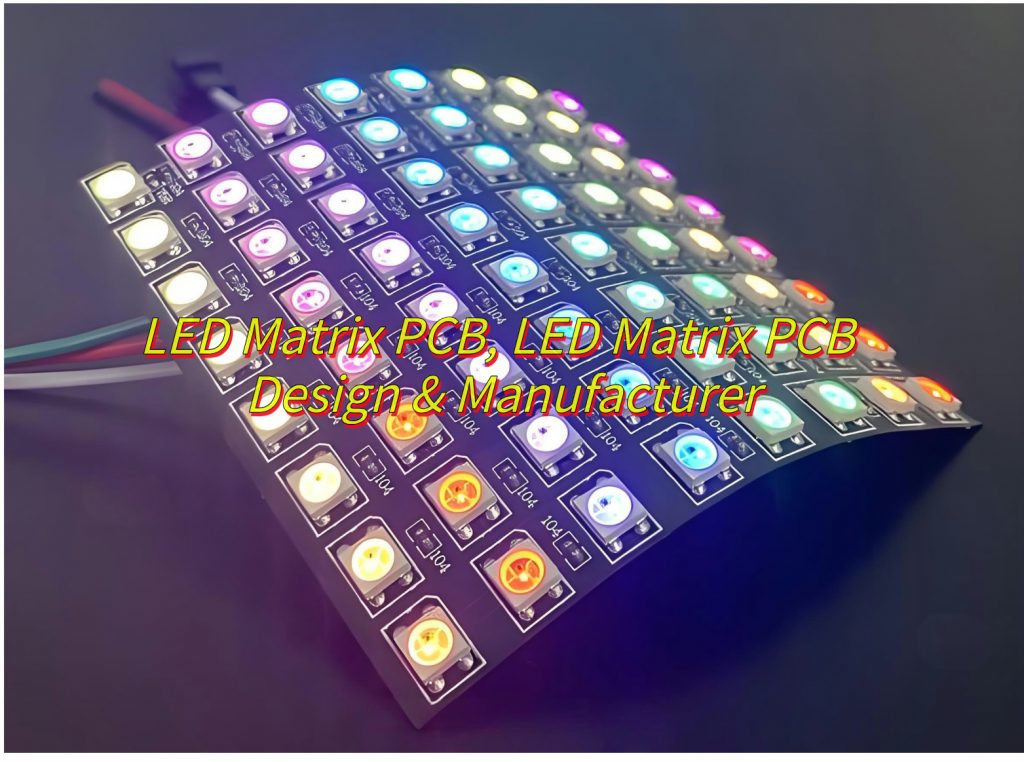
An LED Matrix PCB is a printed circuit board designed to hold multiple light-emitting diodes (LEDs) arranged in a grid pattern (rows and columns). This layout allows individual LEDs or groups to be controlled independently, enabling dynamic lighting effects, text display, or image rendering.

What Advantages of LED Matrix PCBs Board?
Here are advantages of LED Matrix PCB board:
- Uniformity and Consistency: LED matrix boards are designed to ensure even light distribution and color consistency across all LEDs. This is crucial for applications like displays where visual uniformity is essential.
- Efficient Thermal Management: These boards are engineered with effective heat dissipation mechanisms, preventing overheating and ensuring the longevity of the LEDs. This is particularly important in high-brightness applications.
- High Brightness and Clarity: LED matrices provide superior brightness and clarity, making them ideal for outdoor displays, lighting, and other applications where visibility is critical.
- Energy Efficiency: LEDs are inherently energy-efficient, and matrix boards optimize their performance further, reducing power consumption and operating costs.
- Flexibility and Scalability: These boards can be customized to meet specific application requirements, and their modular design allows for easy scalability.
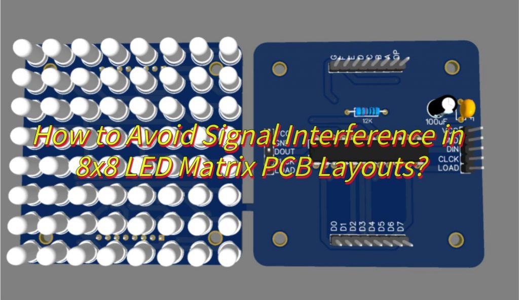
How to Avoid Signal Interference in 8×8 LED Matrix PCB Layouts?
To minimize signal interference in an 8×8 LED matrix PCB layout, follow these structured guidelines:
- Layout Optimization: Separate digital and analog signal traces physically to prevent crosstalk, and use a dedicated ground layer or ground pours to shield sensitive signals.
- Routing Strategies: Employ differential pairs for critical signals like data lines to enhance noise immunity, and keep signal loops small to reduce susceptibility to electromagnetic interference (EMI).
- Decoupling Capacitors: Place decoupling capacitors close to power-hungry components (e.g., LED drivers) to provide local charge reserves.
- Shielding and Isolation: Use shielding enclosures or isolation layers to protect sensitive analog or high-speed digital signals.
- Grounding Techniques: Implement multi-point grounding to lower ground impedance and mitigate ground bounce.
- Simulation and Testing: Validate designs with electromagnetic simulation tools to predict and mitigate interference, and prototype and test under real-world conditions to fine-tune the layout.

How to Design SMD LED Matrix PCB to Improve Heat Dissipation?
To make an SMD LED matrix PCB design with improved heat dissipation, consider the following structured approach:
1. Material Selectionâ
- Substrateâ: Use âmetal-core PCBs (aluminum/copper)â or high-thermal-conductivity âceramic substrates.
- Bondingâ: Apply âsintered silver pasteâ (>50 W/ m ·K ) for die attachment.
2. Thermal Pathway Designâ
- Vertical Pathâ: Minimize thicknessâkeep PCB height â€0.8mm.
Direct Contactâ: Integrate âexposed copper padsâ (â„70% base area) for heatsink attachment.
3. Heat Spreading Structuresâ
- Embedded Copper Slugsâ: Integrate thick copper blocks (â„1mm) under high-power LEDs to distribute heat laterallyâ.
- Thermal Viasâ: Implement dense via arrays (â„5 vias per LED pad) to enhance heat transfer between layersâ.
4. Layout Optimizationâ
- Spacingâ: Maintain â„3mm between high-power LEDs to avoid thermal overlap.
- Copper Tracesâ: Use â„2oz copper layers for improved heat distribution.
5.Manufacturing Efficiencyâ
- Passive Cooling Integrationâ: Leverage existing structural components (e.g., LCD support frames) as heatsinks to reduce costsâ.
- Simulation-Driven Designâ: Perform thermal modeling to validate heat dissipation efficiency before prototypingâ.
â6.Validation and Testingâ
- Thermal Cycling Testsâ: Verify long-term reliability under repeated temperature fluctuationsâ.
- Infrared Imagingâ: Use thermal cameras to identify hotspots and optimize heat distributionâ.
How to Save Costs for LED Matrix PCB Manufacturing?
To save costs in LED matrix PCB manufacturing, follow these tips:
- Simplify Design: Reduce PCB layers and simplify component layout to decrease manufacturing complexity.
- Standardize Components: Use standard components and common packages to improve procurement efficiency.
- Bulk Purchasing: Purchase components and materials in bulk to obtain discounts.
- Choose Cost-Effective Materials: Select PCB materials and components that offer the best cost-performance ratio.
- Optimize PCB Size: Minimize PCB dimensions to reduce material costs and manufacturing fees.
- Select Low-Cost Manufacturers: Evaluate and choose PCB manufacturers that offer cost-effective solutions.
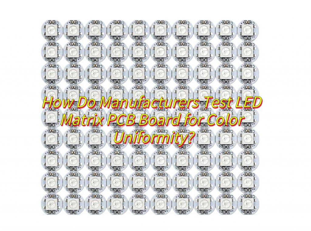
How Do Manufacturers Test LED Matrix PCB Board for Color Uniformity?
Manufacturers test LED matrix PCB boards for color uniformity using several methods:
- Visual Inspection: Initial assessment is done by human inspectors to check for obvious color variations.
- Spectrophotometer Measurements: Precise color and brightness measurements are taken using spectrophotometers.
- Imaging Systems: Imaging systems capture images of the LED matrix for detailed color analysis.
- Automated Testing Systems: Automated systems are used to enhance testing efficiency and accuracy.
- Environmental Control: Testing is conducted in controlled environments to minimize external interference.
- Statistical Process Control (SPC):SPC methods are applied to monitor and improve color uniformity.
- Calibration and Maintenance: Regular calibration of testing equipment ensures accurate results.

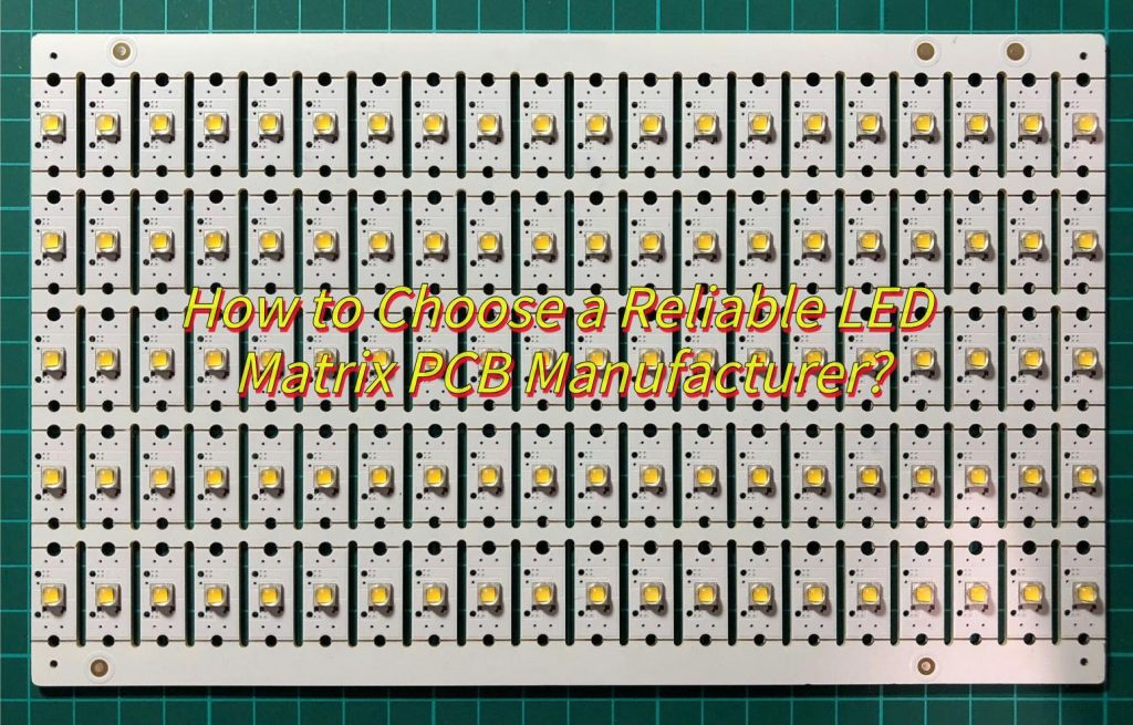
How to Choose a Reliable LED Matrix PCB Manufacturer?
To choose a reliable LED Matrix PCB manufacturer, consider the following:
- Quality Certifications: Verify if the manufacturer holds quality certifications like ISO 9001.
- Experience and Expertise: Assess the manufacturer’s experience and expertise in LED PCB manufacturing.
- Customer Reviews and References: Check customer reviews and references to gauge the manufacturer’s reputation.
- Manufacturing Capabilities: Evaluate the manufacturer’s production capabilities, including equipment and technology.
- Quality Control Processes: Understand the manufacturer’s quality control processes to ensure product standards.
- Cost-Effectiveness: Compare quotes from different manufacturers to choose a cost-effective partner.
- Communication and Support: Assess the manufacturer’s communication skills and after-sales support for a smooth partnership.

Should RGB LED Matrix PCBs Use Common Anode or Cathode Configurations?
When choosing between common anode and common cathode configurations for RGB LED matrix PCBs, consider control complexity and power consumption. Common anode simplifies control but may increase power usage, while common cathode offers precise control with potentially lower power consumption but requires more complex circuitry. Select based on your application’s needs for control precision and cost.


