

Want to master LED PCB circuit board design? This guide covers its materials, application, emergency lighting, Bluetooth control, testing, and OEM fabrication.
EBest Circuit (Best Technology) specialize in LED PCB circuit board manufacturing, delivering rapid 15-day lead times for bulk orders and industry-leading 24-hour prototyping without compromising IPC Class 3 quality standards. Our aluminum base substrates achieve 8W/m·K thermal conductivity for optimized LED heat dissipation, backed by AOI and X-ray inspections ensuring ≤0.01% defect rates across production batches. Advanced SMT lines maintain ±0.05mm component placement accuracy, guaranteeing consistency from prototypes to 100,000-unit orders. The automated CAM engineering system enforces DFM checks for LED spacing layouts, copper balancing, and solder mask alignment, preventing thermal stress failures in high-power applications. With ISO 9001-certified processes and RoHS-compliant materials, we achieve 99.95% on-time delivery for automotive-grade LED modules and emergency lighting systems. Dedicated engineering teams provide 24/7 technical support for Bluetooth integration, dimming circuits, and EMI mitigation – all supported by UL-recognized FR-4 and metal core PCB options. Clients across 18 countries trust our capability to scale LED projects from R&D to mass production while maintaining <1% color temperature variance across lighting arrays. Welcome to contact us if you have any request for LED PCB circuit board: sales@bestpcbs.com.
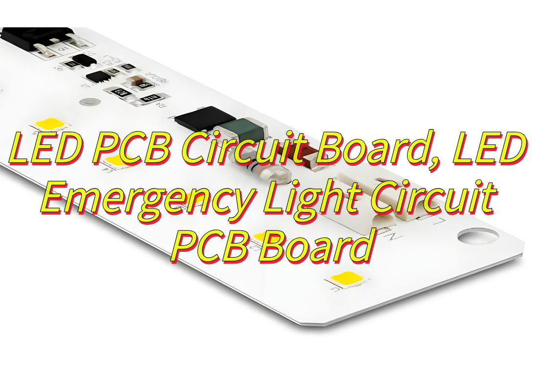
What Is LED PCB Circuit Board?
A LED PCB circuit board is a printed circuit board specifically engineered to mount, power, and manage light-emitting diodes (LEDs). It combines electrical pathways, thermal management layers, and structural elements to ensure stable operation and longevity of LEDs. LED PCB circuit boards often utilize materials like aluminum cores or ceramic substrates to efficiently dissipate heat generated by high-intensity LEDs, preventing performance degradation. Copper traces distribute power evenly across the board, while solder masks protect circuitry from environmental factors. LED PCB circuit board are critical in applications such as LED emergency light circuits, where reliability during power outages depends on robust thermal control and energy-efficient designs. They also enable advanced integrations like Bluetooth circuit board LED systems, where compact layouts support wireless control alongside LED arrays for smart lighting. The design accommodates varying LED densities and environmental demands, from waterproof housings in outdoor signage to vibration-resistant assemblies in automotive lighting. By merging electrical precision with thermal engineering, these boards form the foundation of modern, adaptable lighting solutions in residential, industrial devices.
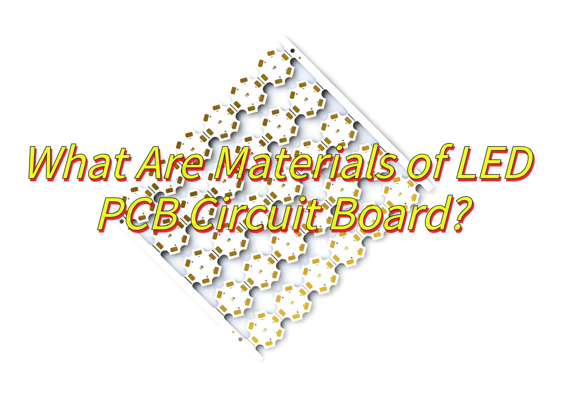
What Are Materials of LED PCB Circuit Board?
Here are the materials commonly used in LED PCB circuit board:
Metal Core Substrates
- Aluminum: Lightweight, cost-effective, and excellent for heat dissipation. Suitable for LED bulbs and emergency lights.
- Copper: Offers superior thermal performance and durability. Ideal for high-precision LED systems.
- Iron Alloys: Provide mechanical rigidity for industrial LED fixtures.
FR-4 Glass Epoxy Composite
- A standard substrate for low-to-medium power LED circuits. It is low-cost, electrically insulating, and easy to manufacture. However, it requires additional heat sinks for high-power applications.
Flexible PI (Polyimide) Substrates
- Enables bendable or conformable LED designs. It is lightweight, resistant to chemicals and moisture, and suitable for LED strips and wearable lighting.
Ceramic Substrates
- Alumina: Affordable, electrically insulating, and stable.
- Aluminum Nitride: Ultra-high thermal conductivity and low thermal expansion. Critical for high-reliability LED applications like automotive headlights.
Conductive Layer Materials
- Copper Foils: Available in various thicknesses for different LED assembly needs.
- Silver/Gold Coatings: Used for high-frequency LED drivers or RF applications.
Thermal Interface Materials (TIMs)
- Thermal Grease: Low-cost and easy to apply.
- Thermal Pads: Pre-cut for convenient use with SMD LEDs.
- Phase-Change Materials (PCMs): Enhance heat transfer at high temperatures.
Solder Materials
- Tin-Lead (Sn63/Pb37): A traditional alloy for wave soldering.
- Lead-Free Alternatives: Such as SAC305 (Sn/Ag/Cu) and bismuth alloys, which are environmentally friendly and suitable for specific LED assembly requirements.
Protective Coatings
- Solder Mask: Insulates copper traces and prevents oxidation.
- Conformal Coatings: Provide moisture and dust resistance for outdoor LED fixtures.
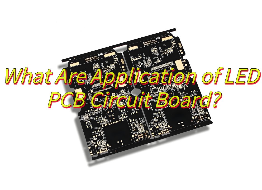
What Are Application of LED PCB Circuit Board?
Application of LED PCB circuit board:
General Lighting Solutions
- Residential & Commercial Lighting: LED PCBs power energy-saving LED bulbs, tube lights, and panel lights for homes, offices, and retail spaces, offering longer lifespans and lower power consumption than traditional options.
- Outdoor Lighting: Used in streetlights, floodlights, and landscape lighting due to their high brightness and resistance to weathering.
- Specialty Lighting: Includes plant growth lamps, aquarium lights, and medical examination lamps, where precise light spectrums and intensity are critical.
Advanced Display Systems
- LED Displays: Found in billboards, stadium screens, and event stages, providing high-resolution visuals with vivid colors and wide viewing angles.
- Mini/Micro LED Technology: Enables ultra-thin TVs, monitors, and wearable devices like smartwatches, combining sharp imagery with low energy use.
- Digital Signage: Used in retail stores, airports, and transportation hubs for dynamic content display.
Automotive Innovation
- Vehicle Lighting: Headlights, taillights, and brake lights utilize LED PCBs for instant illumination, energy efficiency, and compact design.
- Interior Systems: Dashboard indicators, infotainment screens, and ambient lighting rely on LED PCBs for clarity and reliability.
- Safety Features: Advanced driver-assistance systems (ADAS) and blind-spot monitors integrate LED components for enhanced visibility.
Consumer Electronics
- Smartphones & Tablets: LED PCBs manage backlighting for screens and indicator lights, ensuring consistent performance.
- Home Appliances: Refrigerators, washing machines, and air conditioners use LED displays for user interfaces and status indicators.
- Gaming & Entertainment: LED-backlit keyboards, gaming mice, and VR headsets deliver immersive experiences.
Medical & Healthcare Equipment
- Surgical Lighting: High-intensity LED PCBs provide shadow-free illumination in operating rooms, improving precision during procedures.
- Diagnostic Devices: Endoscopes and dental instruments use LED PCBs for reliable, cool-running light sources.
- Patient Monitoring: LED indicators on heart rate monitors, blood pressure devices, and ventilators ensure clear readability.
Industrial & Telecommunications
- Control Panels: LED PCB circuit board power indicator lights and displays in factory machinery, power plants, and automation systems.
- Telecom Infrastructure: Base stations and network equipment use LED PCBs for status signaling and low-maintenance operation.
- Robotics: Collision-avoidance systems and sensor arrays in industrial robots leverage LED technology for accuracy.
Aerospace & Defense
- Aircraft Lighting: Cockpit instruments, cabin lights, and exterior markers use LED PCBs for lightweight, shock-resistant solutions.
- Military Equipment: Night-vision devices, targeting systems, and portable communication tools rely on LED durability in harsh conditions.
Emerging Technologies
- Smart Lighting: IoT-enabled LED PCBs adjust brightness and color temperature via sensors and apps, optimizing energy use in smart homes and cities.
- Automotive LED PCBs with Dual-Channel Cooling: Enhance thermal management in high-power applications like matrix headlights, improving efficiency and lifespan.
How to Design A LED Emergency Light Circuit PCB Board?
Designing a LED emergency light circuit PCB board requires careful consideration of functionality, reliability, and compliance with safety standards. Below is a structured guide to help you create an efficient and durable PCB for emergency lighting applications:
1. Define Requirements & Specifications
- Purpose: Determine the application (e.g., building exits, industrial facilities, or home use) to set brightness, emergency runtime, and auto-switching speed (e.g., ≤5 seconds for high-risk areas).
- Compliance: Adhere to standards like GB17945-2000 (China) or EN 1838 (EU) for emergency lighting, ensuring requirements like minimum 90-minute runtime and insulation resistance (≥50MΩ).
2. Circuit Design
Power Management:
- Auto-Switching Circuit: Use a relay or MOSFET to switch from mains power to battery backup during outages.
- Battery Charging: Implement a constant-current charger with overcharge protection (e.g., ≤0.05C5A) and trickle-charge mode.
Protection Features:
- Over-Discharge Protection: Cut off battery discharge at ≥80% of rated voltage to prolong lifespan.
- Fault Detection: Add indicators (e.g., yellow LED) for issues like broken battery connections.
LED Driver: Select a driver IC (e.g., MT7201) supporting wide input voltage (7–30V) and adjustable current (up to 1A) for different LED configurations.
3. PCB Layout & Wiring
Component Placement:
- Prioritize critical parts (e.g., controller IC, battery terminals) near the center to minimize trace lengths.
- Group LEDs symmetrically for uniform light distribution (e.g., 360° coverage in warning lights).
Thermal Management:
- Use metal-core PCBs (aluminum/copper) for high-power LEDs to dissipate heat efficiently.
- Add via arrays and thermal pads under LEDs to enhance heat transfer.
Signal Integrity:
- Keep high-current traces (e.g., battery lines) short and wide (≥20mil) to reduce voltage drop.
- Isolate noisy traces (e.g., switching circuits) from sensitive analog sections.
4. Material Selection
- Substrate: FR-4: Cost-effective for low-power designs; Metal-Core PCBs: Essential for high-power LEDs to prevent overheating.
- Conductive Layer: Use 1–4 oz/ft² copper foil for current-carrying capacity; apply ENIG (Electroless Nickel Immersion Gold) finish for solderability and corrosion resistance.
- Solder Mask: White or black mask to reflect/absorb light, depending on design needs.
5. Testing & Validation
Functional Testing:
- Simulate power outages to verify auto-switching and battery runtime.
- Check charge cycles (≤24 hours) and fault alerts (e.g., yellow LED activation).
Reliability Testing:
- Thermal Cycling: Expose the PCB to -20°C to 85°C cycles to assess solder joint durability.
- Accelerated Lifetime Test: Operate LEDs at elevated currents (e.g., 50mA vs. 10mA nominal) to predict long-term performance.
Safety Certification:
- Test insulation resistance (≥50MΩ) and withstand voltage (1500V AC for 60s) to meet IEC 62560 standards.
6. Manufacturing Considerations
- Assembly: Use selective soldering for through-hole components (e.g., connectors) to avoid damaging heat-sensitive parts.
- Quality Control: Implement AOI (Automated Optical Inspection) to detect solder defects and misaligned components.
7. Final Integration
- Enclosure Design: Ensure the PCB fits snugly in a fire-resistant housing with ventilation slots for airflow.
- Labeling: Add markings for test buttons, battery replacement, and compliance icons.
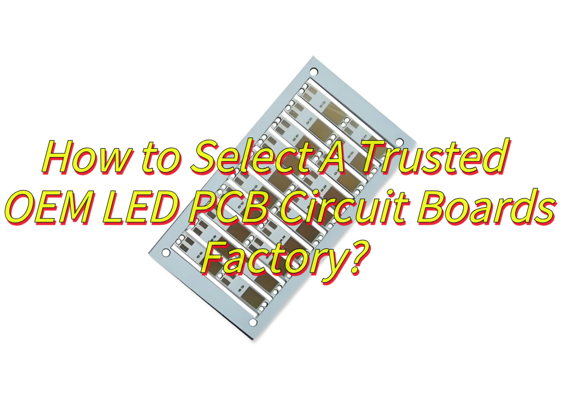
How to Select A Trusted OEM LED PCB Circuit Boards Factory?
To select a trusted OEM LED PCB circuit boards factory, consider the following factors to ensure quality, reliability, and value for your project:
Quality Certifications & Standards
- Verify the factory holds certifications like ISO 9001 (quality management), ISO 14001 (environmental management), and UL (safety compliance). These certifications indicate adherence to global standards.
- Check if the factory follows industry-specific standards such as IPC-A-600 (acceptability of PCBs) and IPC-6012 (performance requirements for rigid PCBs).
Production Capabilities & Technology
- Equipment: Ensure the factory uses advanced machinery like SMT (Surface Mount Technology) lines, AOI (Automated Optical Inspection) systems, and X-ray detectors for precise assembly and defect detection.
- Technical Expertise: Assess their experience with LED PCBs, including thermal management for high-power applications and compatibility with SMD (Surface Mount Device) components.
Material Sourcing & Traceability
- Confirm the factory uses certified materials (e.g., FR-4, metal-core substrates) from reputable suppliers. Ask for material certificates (e.g., UL yellow cards) to verify compliance with safety and performance standards.
- Ensure they implement traceability systems to track raw materials through production, aiding in quality control and accountability.
Quality Control Processes
- Inquire about their inspection protocols, including incoming material checks, in-process testing (e.g., electrical continuity, solderability), and final product audits (e.g., thermal cycling, impedance testing).
- Request samples or pilot runs to evaluate consistency, dimensional accuracy, and performance under stress (e.g., high-temperature tests).
Customer Service & Communication
- Evaluate responsiveness and clarity in pre-sales and technical discussions. A reliable factory should provide detailed quotes, design feedback, and clear timelines.
- Check if they offer engineering support (e.g., DFM – Design for Manufacturability reviews) to optimize your PCB layout for cost and performance.
Pricing & Lead Times
- Compare quotes from multiple factories, but prioritize transparency over low costs. Hidden fees (e.g., tooling, testing) can inflate expenses.
- Confirm lead times align with your project schedule and include buffer periods for potential delays.
Client References & Case Studies
- Ask for references from clients in your industry or with similar product requirements. Contact these references to gauge satisfaction with quality, reliability, and after-sales support.
- Review case studies or portfolios showcasing their work on LED PCBs, especially emergency lighting or Bluetooth-enabled boards.
Ethical & Environmental Practices
- Ensure the factory complies with labor laws and environmental regulations (e.g., RoHS, REACH). Inquire about waste management and energy efficiency initiatives.
How to Test the Quality of LED Emergency Light Circuit PCB Board?
Below is a structured approach to evaluating its quality:
Functional Testing
- Auto-Switching Function: Simulate power outages to verify the PCB switches from mains to battery backup within ≤5 seconds (as per safety standards).
- Battery Performance:
- Test charge cycles (e.g., 24-hour full charge) and discharge runtime (minimum 90 minutes for emergency compliance).
- Check overcharge/over-discharge protection by intentionally overloading the battery.
- LED Output: Measure luminous flux (lumens) and color temperature to ensure consistency with design specifications.
- Fault Detection: Trigger scenarios like broken battery connections or open LED circuits to confirm fault indicators (e.g., yellow LED) activate correctly.
Thermal Testing
- Heat Dissipation: Use thermal imaging to check for hotspots on metal-core PCBs during prolonged operation. Ensure temperatures stay below component ratings (e.g., ≤85°C for capacitors).
- Thermal Cycling: Expose the PCB to -20°C to 85°C cycles (50–100 cycles) to assess solder joint durability and material expansion/contraction effects.
Environmental Durability
- Humidity Resistance: Test in a chamber (85% RH, 40°C) for 96 hours to check for corrosion or insulation breakdown.
- Vibration Testing: Simulate transport/installation vibrations (e.g., 2G, 5–500Hz) to ensure no loose components or trace fractures.
- Chemical Exposure: Verify PCB resistance to cleaning agents or industrial solvents (if applicable).
Electrical Safety Testing
- Insulation Resistance: Measure with a megohmmeter (≥50MΩ between live parts and enclosure).
- Dielectric Withstand Voltage: Apply 1500V AC for 60 seconds to confirm no breakdown occurs.
- EMI/EMC Compliance: Check for electromagnetic interference (e.g., using a spectrum analyzer) to ensure compliance with FCC/CE standards.
Reliability & Lifetime Testing
- Accelerated Life Test: Operate LEDs at elevated currents (e.g., 50mA vs. 10mA nominal) to simulate 5–10 years of use.
- Switching Endurance: Cycle the PCB between mains and battery modes ≥10,000 times to verify relay/MOSFET durability.
Compliance Verification
- Safety Standards: Confirm adherence to GB17945-2000 (China), EN 1838 (EU), or UL 924 (US), including emergency runtime, light distribution, and markings.
- Certification: Request third-party lab reports (e.g., TÜV, SGS) for critical tests like flame retardancy (UL 94 V-0).
Final Inspection
- Visual Audit: Use microscopes to check for solder defects, misaligned components, or PCB delamination.
- Functional Burn-In: Run the PCB at full load for 48–72 hours to identify early-life failures.
How to Integrate Bluetooth Control in LED Emergency Light Circuits?
To integrate Bluetooth control into an LED emergency light circuit, follow these steps to ensure seamless wireless functionality, reliability, and compliance with safety standards:
Hardware Selection
- Bluetooth Module: Choose a low-power module like HC-05 (classic Bluetooth) or DX-BT04-E (BLE 4.2) for compatibility with smartphones. Ensure it supports UART communication and 3.3V/5V power.
- Microcontroller: Use a robust MCU such as STM32F103C8T6 or GD32F427V-START with sufficient I/O ports and serial interfaces (e.g., USART) for Bluetooth and LED control.
- LED Driver: For high-power LEDs, select a constant-current driver IC (e.g., MT7201) with PWM support for dimming. Pair with MOSFETs or relays for switching.
- Power Management: Include a battery backup system (e.g., Li-ion) with a charging IC (e.g., TP4056) and voltage supervision for automatic mains-to-battery switching during outages.
Circuit Design
- Bluetooth-MCU Wiring: Connect the module’s TX/RX pins to the MCU’s RX/TX pins (e.g., PB6/PB7 for USART0). Power the module via a 3.3V regulator if the MCU’s output is insufficient.
- LED Control: Drive LEDs through the MCU’s GPIO or PWM channels. Use metal-core PCBs for high-power LEDs to dissipate heat effectively.
- Battery Circuit: Implement overcharge/over-discharge protection using a dedicated IC (e.g., DW01) and add a voltage detector to trigger emergency mode during power failures.
Firmware Development
- Serial Communication: Configure the MCU’s UART (e.g., 9600 baud) to receive Bluetooth data. Enable interrupts for real-time command processing.
- Command Protocol: Define a simple protocol (e.g., “ON”, “OFF”, “BRIGHT:50”) to control LED states. Parse incoming strings to adjust PWM duty cycles or GPIO outputs.
- Emergency Logic: Program the MCU to switch to battery power automatically when mains voltage drops below a threshold. Add fault indicators (e.g., yellow LED) for low battery or connection issues.
Mobile App Development
- Bluetooth Pairing: Develop an Android/iOS app using frameworks like MIT App Inventor or Android Studio. Include functions to scan, pair, and connect to the Bluetooth module.
- User Interface: Design buttons for ON/OFF control, a slider for brightness adjustment, and toggles for emergency modes. Display battery status and connection indicators.
- Data Exchange: Send commands via the app’s Bluetooth interface (e.g., “BRIGHT:75” for 75% intensity). Implement feedback loops to confirm command execution.
Testing & Optimization
- Functional Testing: Verify Bluetooth range (typically 10–100m), command latency, and emergency switching speed (≤5 seconds). Test battery runtime under load (minimum 90 minutes per EN 1838).
- Signal Stability: Check for dropped connections in environments with Wi-Fi/2.4GHz interference. Use a spectrum analyzer to identify noise sources.
- Power Efficiency: Optimize MCU sleep modes and Bluetooth advertising intervals to reduce idle current (ideally <100µA).
- Thermal Management: Run LEDs at full load for 24 hours to validate heat sink performance. Ensure PCB temperatures stay below component ratings (e.g., ≤85°C for capacitors).
Compliance & Certification
- Safety Standards: Test insulation resistance (≥50MΩ) and dielectric withstand voltage (1500V AC). Ensure compliance with IEC 62560 and local emergency lighting regulations.
- EMC Testing: Verify electromagnetic compatibility (EMI/EMS) to prevent interference with other devices.
How to Order LED Light Metal Circuit Board PCB Fabrication Online?
To order LED light metal circuit board PCB fabrication online, follow these steps to ensure accuracy, quality, and cost-effectiveness:
Select a Reputable Online PCB Manufacturer
- Choose platforms like EBest Circuit (Best Technology) with user-friendly interfaces and positive reviews for metal-core PCBs.
- Verify they offer materials like aluminum (cost-effective) or copper (high thermal performance) suitable for LED applications.
Prepare Design Files
- Gerber Files: Export your PCB design in standard Gerber format (RS-274X) using software like Altium, Eagle, or KiCad. Include layers for copper traces, solder mask, and silkscreen.
- Drill File: Provide an Excellon drill file with precise hole dimensions for LEDs, components, and mounting points.
- BOM & Assembly Drawings: List components with part numbers and tolerances. Include a mechanical drawing with board dimensions and tolerances (e.g., ±0.1mm).
Configure PCB Specifications
- Material: Select aluminum (most common for LEDs) or copper for higher thermal conductivity. Specify thickness (e.g., 1.0mm, 1.6mm).
- Layers: Choose 1-layer (simple LED strips) or 2-layer (complex circuits) based on design complexity.
- Surface Finish: Opt for ENIG (Electroless Nickel Immersion Gold) for solderability and corrosion resistance, or HASL (Hot Air Solder Leveling) for cost savings.
- Solder Mask: Use white to reflect light or black to absorb it, depending on design needs.
- Silkscreen: Add component labels and polarity markers in a contrasting color (e.g., white on black mask).
Upload Files & Review Quotes
- Use the manufacturer’s online tool to upload Gerber, drill, and BOM files.
- Check the automated quote for errors (e.g., missing layers, incorrect dimensions). Adjust specifications if needed to balance cost and quality.
Place Order with Customization
- Quantity: Order in batches (e.g., 5–10 panels) to reduce per-unit costs.
- Lead Time: Select standard (5–7 days) or expedited (2–3 days) shipping based on project deadlines.
- Additional Services: Add stencil (for SMD assembly), impedance control (for high-speed signals), or flying probe testing (for prototype validation).
Payment & Tracking
- Pay via secure methods like PayPal, credit card, or bank transfer.
- Track order status through the manufacturer’s portal (e.g., “Order Confirmed,” “In Production,” “Shipped”).
Quality Inspection
- Visual Check: Verify board dimensions, hole alignment, and solder mask registration upon delivery.
- Electrical Test: Use a multimeter to check continuity and insulation resistance.
- Thermal Test: For high-power LEDs, confirm heat dissipation using thermal imaging.
Assembly (If Needed)
- SMT Assembly: Provide a centroid file and stencil for automated SMD component placement.
- Through-Hole Assembly: Specify wave soldering or manual soldering for LEDs and connectors.
In conclusion, that’s all about LED PCB circuit board’s materials, benefits, emergency lighting, Bluetooth control, testing, and OEM fabrication. If you have any issues with LED PCB circuit board, welcome to leave a message below this blog.