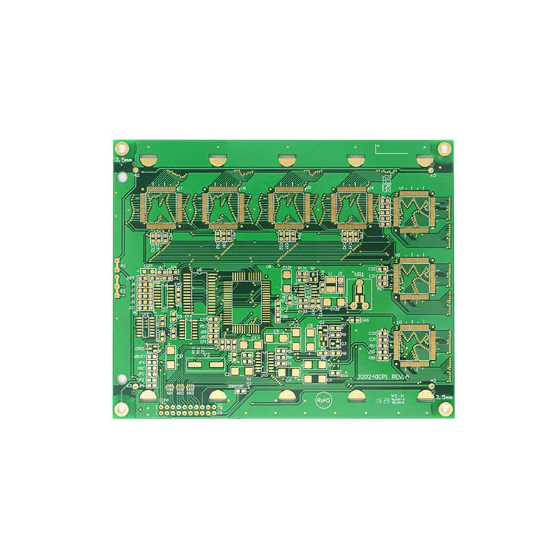
How to choose IT170GRA2 material? Let’s discover definition, datasheet, benefits, applicable frequency range, cost and alternative solution for IT-170GRA2.
Are you troubled with these questions?
- How to prevent signal attenuation from material loss in high-frequency transmission?
- How to manage heat in multi-layer PCBs while maintaining high-density routing efficiency?
- How to shorten prototyping cycles for rapid design validation and market entry?
As a high speed PCB manufacturer, EBest Circuit (Best Technology) can provide you service and solution:
- IT170GRA2 material delivers ultra-low loss with dissipation factor ≤0.002 at 10GHz, ensuring cleaner signal integrity and 30% higher first-pass design success.
- Thermal conductivity ≥3.0W/m·K combined with optimized heat dissipation paths reduces board temperature rise by 15% in high-density designs, eliminating thermal stress risks.
- 48-hour rapid prototyping and direct material database access cut design iteration time in half, doubling speed-to-market for competitive edge.
Welcome to contact us if you have any request for high speed PCB: sales@bestpcbs.com.
What Is IT170GRA2?
IT170GRA2 is a high-performance copper-clad laminate (CCL) manufactured by ITEQ, specifically designed for high-speed and high-frequency printed circuit board (PCB) applications. The model name encodes its core features: “IT” stands for the brand ITEQ, “170” indicates a glass transition temperature (Tg) exceeding 170°C (verified at 175°C via DSC testing), “GR” denotes glass fiber reinforced substrate, “A” signifies a halogen-free environmental formulation (RoHS compliant), and “2” represents the second-generation optimized version.
Compared to its predecessor (e.g., IT-170GRA1), it achieves reduced dielectric loss (Df≈0.012) and enhanced anti-CAF (anti-ionic migration) performance. Defined as an epoxy resin/glass fiber cloth-based high Tg halogen-free CCL, it combines low signal loss, high thermal resistance (Tg=175°C), and high reliability, making it ideal for high-speed scenarios including 5G communication systems, server backplanes, and automotive electronic control units.

IT170GRA2 Material Datasheet
| Parameter Category | Specification Value | Test Standard |
| Glass Transition Temp (Tg) | 175°C | DSC Method (IPC-TM-650 2.4.25) |
| Dielectric Constant (Dk) | 3.85±0.05 @10GHz | IPC-TM-650 2.5.5.13 (Stripline Method) |
| Dielectric Loss (Df) | 0.012 @10GHz | Same as Dk (Stripline Method) |
| CTE (Coefficient of Thermal Expansion) | X/Y Axis: 12 ppm/℃;Z Axis: 45 ppm/℃ (50–260°C) | TMA Method (IPC-TM-650 2.4.24) |
| Anti-CAF Performance | Passed 85°C/85%RH, 50V, 1000h | IPC-650 2.6.25 |
| Flame Retardancy | UL 94 V-0 | UL Standard |
| Copper Foil Peel Strength | ≥0.7 N/mm (Normal Condition) | IPC-TM-650 2.4.8 |
| Thickness Range | 0.04–3.2 mm | None (Basic Dimension Specification) |
| Copper Thickness Range | 1/3oz–4oz | None (Supporting Process Parameters) |
Why Choose IT170GRA2 Material for High Speed PCB?
Reasons Why Choose IT-170GRA2 Material for High Speed PCB:
- High-Frequency Signal Low-Loss Transmission: Df value 0.009–0.012 (@10GHz) reduces signal loss by approximately 40% compared to FR-4, ensuring signal integrity for 25Gbps+ high-speed links (e.g., PCIe 5.0) and minimizing data transmission errors.
- Stable Performance in High-Temperature Environments: Tg=175°C supports lead-free soldering processes, Z-axis CTE of 45ppm/℃ minimizes interlayer separation, and passing 85°C/85%RH 1000h CAF test extends service life in high-temperature scenarios like 5G base stations and automotive electronics.
- Environmentally Compliant and Safe: Halogen-free formulation meets RoHS/IEC 61249-2-21 standards, UL 94 V-0 flame retardancy enhances terminal product safety, complying with global environmental regulations.
- High Process Compatibility and Cost Efficiency: Supports advanced processes like laser drilling and HDI stacking, copper foil peel strength ≥0.7N/mm prevents detachment during processing. Cost is 30%+ lower than ultra-low loss materials (e.g., Megtron 6), achieving 80% of FR-4 performance at 10–25GHz scenarios, balancing performance and cost.
- Precise Impedance Control: Dk value 3.85±0.05 (@10GHz) maintains stable frequency variation, supports ±3% tolerance impedance design, avoids signal reflection issues, suitable for precision requirements like 100G optical modules in data centers.
- Multi-Scenario Verified Reliability: 10GHz insertion loss ≤-0.8dB/inch in 5G base station RF front-end boards, 77GHz automotive radar withstands thermal cycling (-40°C~150°C) without delamination, 56G PAM4 eye diagram jitter <0.15UI in data centers, validated by real-world test data.

What Frequency Range Is IT-170GRA2 Suitable for?
The applicable frequency range of IT-170GRA2 is 10–25GHz, primarily covering mid-to-high frequency scenarios. Its optimal operating range is 10–25GHz, where dielectric loss Df is ≤0.012, ensuring controlled signal loss, for instance, insertion loss at 25GHz is approximately -1.75dB per inch. Beyond 25GHz, Df rises to 0.015–0.020, dielectric constant Dk fluctuates by more than ±0.1, leading to insertion loss exceeding -3dB per inch and impedance mismatch risks. For ultra-high frequency applications (such as 77GHz automotive radar or terahertz scenarios above 30GHz), it is unsuitable due to excessive loss and requires ultra-low loss materials like Megtron 7.

IT170GRA2 Material Selection Guide for High Speed PCB
1. Signal Rate Requirement Assessment
- Determine if the signal rate is ≤56Gbps PAM4 (equivalent frequency ≤28GHz). For rates exceeding this standard, ultra-low loss materials like Panasonic Megtron 6 are required. For lower rates, proceed to temperature adaptability verification.
2. Operating Temperature Adaptability Verification
- Confirm if long-term operating temperature is ≤130°C. For extreme environments exceeding 150°C (e.g., engine ECU), polyimide substrates must be used to ensure thermal stability. If temperature is ≤130°C, proceed to cost budget analysis.
3. Cost Budget Matching Analysis
- Evaluate if the project budget can accommodate ≥1.5 times the cost of FR-4. For ultra-low-cost solutions, standard FR-4 remains viable. For mid-to-high costs, IT-170GRA2 is optimal due to its cost-effectiveness in the 10–25GHz frequency range.
4. Scenario-Based Parameter Configuration
Select recommended configurations based on application scenarios:
- 5G Base Station RF Board: Use 0.25–0.5mm thickness, HVLP low-roughness copper foil, and 2–6 layer symmetric stackup for 50Ω single-ended impedance ±3% control and fiber weave effect compensation.
- PCIe 5.0 Interface Card: Adopt 0.8–1.2mm thickness, RTF reverse copper foil, and 8–12 layer hybrid stackup for 85Ω differential impedance ±2% accuracy and back-drilled stub ≤8mil.
- 100G Optical Module Substrate: Apply 0.15–0.3mm thin board, HVLP copper foil, and 4-layer thin design for 100Ω differential impedance ±3% and golden finger length optimization.
- Automotive ADAS Controller: Utilize 1.5–2.0mm thickness, STD standard copper foil, and 6–8 layer high-Tg core for 90Ω differential impedance ±4% and enhanced thermal stress simulation.
5. Strict Avoidance of Prohibited Scenarios
Strictly prohibit the following four categories:
- Continuous signal frequencies >25GHz (e.g., 77GHz automotive radar) due to excessive loss causing signal failure.
- Long-term high-temperature environments >150°C (e.g., engine ECU) requiring polyimide substrates.
- Ultra-thick ratio structures with board thickness ≥3.2mm and hole diameter <0.2mm (aspect ratio >16:1) risking drilling cracks.
- Strong acid environments with pH <2 where halogen-free resin chemical resistance is insufficient.
6. Cost Optimization Strategy Implementation
- Copper foil substitution: Replacing HVLP with RTF reduces cost by ~8% but increases insertion loss by 0.1dB/inch.
- Thickness adjustment: Optimizing 1.0mm to 0.8mm (via increased layers) reduces cost by ~5% while monitoring Z-axis CTE impact on thermal reliability.
- Avoid hybrid laminates: Outer IT-170GRA2 + inner FR-4 structures, though reducing cost by 15%, risk interlayer mismatch. Prefer single-material solutions.
7. Design Verification and Failure Prevention
- Signal integrity: Simulate 1–25GHz Dk/Df frequency curves and verify 25GHz insertion loss < -2.0dB/inch. Thermal reliability: Pass 3x 288°C reflow tests and ensure Z-axis CTE <50ppm/°C (50–260°C).
- Process compatibility: Confirm copper peel strength >0.6N/mm (1oz copper) and laser drilling parameters (355nm wavelength, pulse <20μJ).

How Much Does IT-170GRA2 Material Cost?
| Specification | Unit Price Range (USD/㎡) |
| 1oz Copper Foil, Thickness 1.0mm | $220–280 |
| 1oz Copper Foil, Thickness 0.2mm | $290–360 |
| 2oz Copper Foil, Thickness 1.6mm | $310–380 |
Alternative Materials of the Same Grade to IT-170GRA2
| Material Model | Manufacturer | Origin | Export Certifications | Dominant Frequency Range | Unit Price (USD/㎡) |
| TU-872SLK | TUC (Taiyao) | Taiwan | UL, CE, RoHS, REACH, IPC-4101E | ≤25 GHz | $210–260 |
| Isola I-Tera MT40 | Isola | USA | UL, MIL-PRF-31032, NADCAP, ITAR (Optional) | ≤20 GHz | $230–290 |
| Panasonic Megtron 6 | Panasonic | Japan | UL, VDE, JIS C 6481, IATF 16949 (Automotive) | ≤40 GHz | $480–550 |
| Doosan DSR-3400 | Doosan | South Korea | UL, KC, RoHS, REACH, ISO 9001/14001 | ≤28 GHz | $250–310 |
| Shengyi S1000-2M | Shengyi (SY) | China | UL, RoHS, REACH (Halogen-Free required for EU export) | ≤18 GHz | $180–230 |
Welcome to contact us if you have any other issues with IT-170GRA2 material: sales@bestpcbs.com.


