PCB manufacturing PCB manufacturing
Home > Blog

Posts Tagged ‘FPC Connector’

FFC vs FPC Connector Comparison for Flexible Applications
Wednesday, January 7th, 2026

FFC vs FPC connector is a critical component in modern electronics, enabling reliable connections for flexible circuits. This article will compare their differences, address common application challenges, and guide you in selecting the right solution for your flexible flat cable​ needs.

Are you struggling with signal integrity, mechanical failures, or assembly headaches in your flexible circuit designs? Many engineers face significant hurdles when integrating FFC and FPC connectors​ into their products.

  • Intermittent connections or signal loss due to poorly mating connectors and cables.
  • Difficulty in manual assembly, leading to damaged cable ends or connector latches.
  • Confusion between FFC vs FPC cable​ specifications, resulting in mismatched components.
  • Signal interference in high-speed applications using standard FFC ribbon cables.
  • Mechanical stress causing failure at the connector junction in dynamic flexing applications.

The solution lies in a clear understanding of the FFC FPC difference​ and partnering with a manufacturer that masters their application. As an experienced FPC and PCBA manufacturer, EBest Circuit (Best Technology) provides not just components but complete integration support.

  • Supplying precision-engineered FFC/FPC connectors​ and cables with guaranteed mating specifications.
  • Offering connectors with Zero Insertion Force (ZIF) or Low Insertion Force (LIF) mechanisms for error-proof assembly.
  • Providing expert guidance to clarify FFC vs FPC connector​ selection based on your specific current rating, spacing, and flexibility needs.
  • Recommending and sourcing shielded FPC ribbon cables​ or specific FPC connector types​ for EMI-sensitive designs.
  • Implementing robust strain relief and optimal board layout in our PCBA manufacturing to enhance flex endurance.

At EBest Circuit (Best Technology), we specialize in the manufacturing and assembly of high-quality Flexible Printed Circuits (FPC) and PCBAs. Our deep expertise in FFC/FPC connectors​ application ensures that your flexible interconnects are reliable, durable, and perfectly suited to your design’s mechanical and electrical demands. For your next project, pls feel free to contact our team at sales@bestpcbs.com.

FFC vs FPC Connector

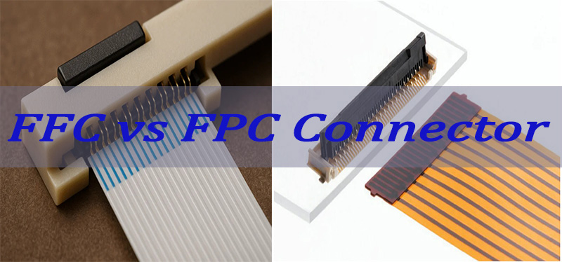
What Is the Difference Between FFC vs FPC Connector?

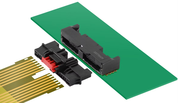
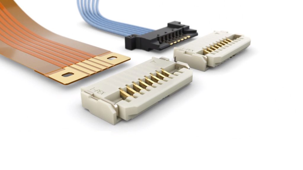
The core difference lies in what they connect. An FPC connector​ is the receptacle soldered onto a PCB, designed to accept a flexible conductor. FFC, meaning Flexible Flat Cable, is the removable cable that plugs into that connector. Think of FPC vs FFC connector​ as a socket versus a plug. The connector’s design must match the cable’s specifications.

FeatureFPC ConnectorFFC Cable
NatureComponent (Receptacle)Cable Assembly (Plug)
ConstructionHousing, contacts, latchFlat parallel conductors laminated in plastic
PermanenceSoldered to PCBRemovable interconnect
CustomizationType (ZIF, LIF, Top/Bottom contact), pin countLength, pin count (e.g., FFC cable 40 pin), pitch, thickness
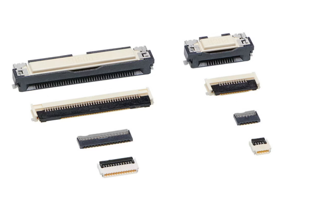
  • FPC Connector Types:​ These are defined by their actuation method (ZIF, LIF, Non-ZIF) and contact orientation (top, bottom, double-sided).
  • FFC Cable Specs:​ Defined by pitch (e.g., 0.5mm, 1.0mm), pin count (FFC cable 6 pin, 8 pin, 30 pin, etc.), length, and thickness.

In summary, the FFC vs FPC​ comparison is symbiotic: the connector is the interface, and the cable is the conductor. Selecting the correct pair is foundational to system reliability.

FFC vs FPC Connector

What Is the Relationship Between FFC and FPC Connectors?

Their relationship is defined by mechanical and electrical compatibility. They form a complete interconnect system. The FPC connector​ is engineered to precisely match the physical dimensions and electrical parameters of the FFC cable.

  • Pitch Compatibility:​ The connector’s contact spacing must exactly match the cable’s conductor pitch (e.g., a 1.0mm pitch connector for a 1.0mm pitch FFC cable 4 pin).
  • Thickness Compatibility:​ The connector’s clamp must accommodate the total thickness of the flexible flat cable FFC.
  • Circuit Alignment:​ The connector’s contacts must align with the cable’s conductors. Some connectors are for “straight” access, others for “right-angle” mating.
  • Actuation Mechanism:​ The cable is inserted and locked using the connector’s latch (ZIF) or a simple friction fit.

The key takeaway is that they are not interchangeable without verifying specs. A mismatch, even by a few microns, can cause poor contact or mechanical failure.

What Is the Purpose of FFC Cable in Flexible Flat Cable Connector Design?

The purpose of the FFC cable​ is to provide a reliable, flexible, and cost-effective conductive link between two PCBs or components within an assembly. Its design directly influences the flexible flat cable connector​ choice.

  • Space Savings:​ Enables dense, three-dimensional packaging impossible with round wires.
  • Reliability:​ Eliminates the risk of individual wire misplacement during assembly vs discrete wiring.
  • Mass Termination:​ All conductors are connected simultaneously upon insertion, drastically reducing assembly time and cost.
  • Controlled Impedance:​ In high-speed designs, FPC ribbon cables​ can be engineered for specific impedance.
  • Repeatable Flexing:​ Designed to withstand repeated bending in applications like hinge connections.

Therefore, the FFC cable​ is the enabling element for modular design and servicing, while the connector ensures its secure and stable interface.

What Are the Common FPC Connector Problems?

Several issues can plague FPC connector​ applications, often stemming from selection, handling, or manufacturing flaws.

  • Poor Contact/Intermittency:​ Caused by contaminated contacts, mismatched cable thickness, or a worn/loose locking mechanism.
  • Cable Misalignment:​ The FFC cable​ is not fully inserted or is offset, leading to shorted or open circuits.
  • Damaged Latches:​ The ZIF/LIF latch is brittle and can break during assembly or disconnection if not handled properly.
  • Mechanical Stress:​ Bending or pulling stress concentrated at the connector-cable junction can tear the cable or break solder joints.
  • Soldering Issues:​ Poor solder joints on the connector’s PCB footprint (e.g., tombstoning, insufficient solder) can cause open circuits.

Understanding these failure modes is the first step in prevention through robust design and assembly practices.

How to Select the Right FFC/FPC Connectors for Your Application?

Selecting the right pair requires a systematic approach based on your design’s electrical, mechanical, and environmental needs.

  • Pin Count & Pitch:​ Determine the number of signals (FFC cable 30 pin) and the available space (pitch: 0.3mm, 0.5mm, 1.0mm).
  • Current Rating:​ Check the current per circuit. Standard FFC cables​ have lower current capacity than thicker custom FPC cables.
  • Stack Height:​ Measure the required space between boards to choose a connector with the correct mating height.
  • Flex Life & Direction:​ Define how often and in what direction the cable will bend. This affects cable construction.
  • Actuation Type:​ ZIF for frequent service, LIF/Non-ZIF for cost-sensitive, permanent applications.
  • Shielding Needs:​ For noisy environments, specify cables with shielding layers and corresponding shielded FPC connector types.

A careful evaluation against this checklist ensures a reliable FFC vs FPC cable​ interconnect system.

FFC vs FPC Connector

How Does the Choice Between FFC vs FPC Connector Impact FPC and PCBA Manufacturing?

The choice directly impacts DFM (Design for Manufacturability), assembly yield, and long-term reliability.

  • Assembly Automation:​ Standardized FFC/FPC connectors​ with pick-and-place friendly packaging enable faster, automated assembly.
  • Soldering Profile:​ The connector’s plastic housing may have a lower maximum temperature than the PCB, requiring a controlled reflow profile.
  • Strain Relief Features:​ The design must include features like adhesive stickers, stiffeners, or board keep-outs to protect the connection point.
  • Test Accessibility:​ The connector’s location must allow for test probe access if needed.
  • Rework Difficulty:​ ZIF connectors are easier to rework than soldered cable ends, affecting serviceability and repair costs.

Integrating connector selection early in the design phase is crucial for manufacturability.

Why an Experienced FPC and PCBA Manufacturer Matters for FFC/FPC Connector Projects?

An experienced partner like EBest Circuit (Best Technology) bridges the gap between component selection and a flawless final product. We understand that FFC vs FPC connector​ success is about the entire ecosystem.

  • Holistic Design Review:​ We assess your schematic and layout for connector placement, strain relief, and potential signal integrity issues.
  • Component Sourcing & Verification:​ We procure genuine, compatible connectors and cables, verifying specs like pitch and thickness before assembly.
  • Process Optimization:​ Our assembly lines are calibrated for sensitive FPC connector​ placement and soldering.
  • Testing & Validation:​ We perform continuity, hipot, and functional tests to ensure every flexible flat cable connector​ interface is flawless.
  • Failure Analysis & Support:​ If issues arise, our expertise allows us to quickly diagnose whether it’s a connector, cable, or assembly problem.

This end-to-end control minimizes risk and ensures your product’s reliability from the first prototype to mass production.

FFC vs FPC Connector

All in all, FFC vs FPC connectors​ form the essential link between portability and functionality in modern electronics. This comparison has highlighted their distinct roles, common pitfalls, and selection criteria to ensure robust flexible applications.

Partnering with a manufacturer that possesses deep expertise in both FPC and PCBA manufacturing​ is crucial. EBest Circuit (Best Technology) provides the integrated design support, precision manufacturing, and quality assurance needed to navigate the complexities of FFC/FPC connectors​ successfully. Let us help you perfect your flexible interconnect design. Pls feel free to contact us anytime at sales@bestpcbs.com for a consultation on your next flexible PCB or SMT assembly project.

FAQs

Are FPC Connectors Waterproof?

Standard FPC connectors​ are not waterproof. They are designed for indoor, controlled environments. For moisture or dust exposure, you need specifically rated IP connectors or must use conformal coating and gasketing as a secondary sealing method.

Can FFC Cables Be Soldered?

Directly soldering an FFC cable​ is generally not recommended and defeats its purpose as a removable interconnect. The laminate insulation can melt, and the fine conductors are easily damaged. Always use a compatible FPC connector​ for a reliable, solderless connection.

What Are FPC Connectors Used For?

FPC connectors​ are used anywhere a compact, reliable, and flexible electrical connection is needed. Common applications include laptop displays (FFC cable 40 pin​ for LCDs), printers, scanners, cameras, medical devices, consumer electronics, and automotive dashboards where connecting PCBs across hinges or moving parts is required.

FPC vs FFC Connector: How to Choose?
Wednesday, December 3rd, 2025

Which is better? FPC vs FFC connector? This guide provides a detailed comparison of their specifications, durability, cost, and reliable suppliers, along with an FAQ section, to empower your design and procurement decisions for optimized performance and reliability.

Are you troubled with these questions?

  • Do your FPC/FFC connector purchases often lead to capital tied up due to high minimum order quantities, disrupting flexible production plans?
  • When facing urgent orders, do supplier delivery delays repeatedly disrupt your product launch timelines?
  • Do your connectors frequently suffer from poor contact or insufficient lifespan under repeated bending or high-temperature environments?

As a FPC and FFC connector supplier, EBest Circuit (Best Technology) can provide you service and solutions:

  • Flexible MOQ: Support small-batch orders starting from 100 pieces with immediate response, reducing inventory holding costs.
  • Rapid Delivery: Standard products delivered within 3-5 days; dedicated channels for urgent orders ensure production continuity.
  • Consistent Quality: Full-process quality control with dual testing for electrical performance and environmental adaptability in every batch, guaranteeing performance consistency.

Welcome to contact us if you have any request for FPC and FFC connector: sales@bestpcbs.com.

What Is A FPC Connector?

A FPC connector is designed to link flexible printed circuits to a rigid PCB or module. It creates a stable electrical interface between thin copper traces on the flexible board and the main circuit. The structure is compact, while the landing area remains very narrow, which helps engineers handle tight mechanical designs. Furthermore, these connectors offer different orientations—top contact, bottom contact, or dual-contact, so designers can manage signal flow based on the device layout.

Because flexible printed circuits bend without stressing the copper, FPC connectors become common in cameras, mobile devices, wearables, and modules with curved surfaces. Additionally, their latch systems, pin counts, and pitch sizes vary widely, giving engineers more room to fine-tune the interface. As devices continue shrinking, these connectors support high-density routing in limited areas without sacrificing electrical performance.

FPC Connector

What Is A FFC Connector?

A FFC connector mates with a flat flexible cable instead of a patterned flexible circuit. The cable uses thin copper strips laminated between insulation layers, forming a ribbon-like shape. While the form is simple, the structure supports stable current flow across short distances with minimal signal loss. Because of this, FFC connectors remain popular in printers, displays, household electronics, vehicle dashboards, and small automation units.

Moreover, the connector body usually adopts a lightweight design with sliding or flip-lock actuators. Engineers can plug and secure the cable with ease during assembly. Pitch options, length choices, and cable thickness also stay diverse, allowing the solution to suit compact or mid-size modules. As a result, FFC connectors deliver consistent performance for devices that require repeatable, low-profile interconnects.

FFC Connector

FPC vs FFC Connector: How to Choose?

Below is a detailed selection guide: FPC vs FFC Connector:

1. Electrical Performance Priority Scenario Selection Strategy

  • High-Frequency Signal Scenarios (≥5GHz): Prioritize FPC connectors, with impedance control accuracy up to ±5Ω, supporting 56Gbps PAM4 transmission (e.g., Molex 502430 series). FFC connectors exhibit ±20Ω impedance deviation, unsuitable for high-frequency requirements.
  • High-Current Transmission Scenarios (≥2A/pin): Recommend FFC connectors, with conductor thickness ≥0.05mm (FPC typically 0.035mm), achieving ≤10mΩ contact resistance via IDC terminals (e.g., TE 1775170).
  • Mixed Signal Design Scenarios: Adopt FPC connectors, enabling integration of resistors/capacitors for rigid-flex boards, effectively avoiding crosstalk risks from parallel FFC lines.

2. Mechanical Environmental Adaptability Selection Logic

  • Dynamic Bending Requirements (>100,000 cycles): Must select FPC connectors, with PI substrate bending life up to 500,000 cycles and ZIF connectors (e.g., Hirose FH12 anti-dislodging design). FFC PET substrate bending life ≤50,000 cycles, prone to fatigue fracture.
  • High-Vibration Scenarios (Automotive/Aerospace): Recommend FPC connectors, with beryllium copper terminals resisting 15G vibration (compliant with USCAR-2). FFC IDC interfaces risk loosening under vibration.
  • High-Temperature Environments (>105°C): Both options viable. FPC with PI substrate withstands 260°C (e.g., JAE FX26). FFC requires custom PI substrate version (+30% cost).

3. Space and Integration Complexity Decision Points

  • Ultra-Thin Design (≤0.8mm): Select FPC connectors, compressible to 0.3mm thickness (e.g., I-PEX 20473). FFC inherently thicker (≥0.6mm) due to insulation-conductor structure.
  • 3D Wiring Requirements: Must adopt FPC connectors, customizable for complex structures like foldable hinge applications. FFC limited to planar routing.
  • Quick Plug-and-Play Maintenance: Recommend FFC connectors, with IDC solder-free interfaces (e.g., Amphenol 20021121). FPC ZIF insertion requires specialized tools.

4. Cost and Supply Chain Economic Analysis

  • Strict Cost Control Scenarios: Prioritize FFC connectors, priced $0.01−$0.05/pin(FPC: $0.03-$0.15/pin). PET material accounts for 60% of FFC costs vs. 30% for FPC materials.
  • Small-Batch Customization Scenarios: Suitable for FPC connectors, with 1-week prototype cycles and laser cutting replacing FFC stamping dies ($5K+ tooling cost).
  • Automotive-Grade Certification Requirements: Both viable. FPC offers AEC-Q200 certified products (e.g., JAE FX26). FFC provides IP67-sealed options (e.g., TE 1775170).

5. Risk Mitigation and Reliability Enhancement Measures

  • High-Frequency Signal Attenuation Risk: Select FPC connectors with ≤0.3mm pitch and gold-plated terminals for impedance matching.
  • Bending Fracture Risk: Avoid sharp bends <1mm radius (PI substrate minimum bending radius = thickness ×10).
  • Contact Oxidation Issues: Use gold-plated terminals (≥0.2μm) instead of tin in humid environments for enhanced corrosion resistance.
  • Insufficient Insertion-Extraction Life: Optimize for FPC connectors with 100,000-cycle certifications (e.g., Hirose FH43).

6. Industry Best Practice References

  • Consumer Electronics: Mobile screen applications prefer FPC (Hirose FH12) for space optimization and bending advantages.
  • Industrial Equipment: PLC module interconnections use FFC (Molex 052331) for $0.02/pin cost efficiency.
  • Medical Endoscopy: FPC (Omron XG5M) recommended for gamma sterilization resistance.
  • Automotive ECU: FPC (TE 1473005) selected for vibration and high-temperature composite tolerance.
FPC vs FFC Connector: How to Choose?

FFC vs FPC Connector Specification Comparison

SpecificationFFC ConnectorFPC Connector
Pitch0.5mm, 1.0mm, 1.25mm, 2.54mm (Standardized)0.1mm~0.5mm (Customizable)
Conductor Thickness0.035mm, 0.05mm (Tin-plated copper)0.012mm~0.035mm (Etched copper foil)
Temperature Resistance RangePET substrate: -40°C~105°C; PI substrate: -269°C~260°CPI substrate: -269°C~260°C (Mainstream)
Current Carrying Capacity0.5A/pin (0.05mm thickness)0.3A/pin (0.035mm thickness)
Flex LifeDynamic: 10,000~50,000 cycles; Static: PermanentDynamic: 100,000~500,000 cycles (PI substrate)
Impedance Control±20Ω (High-frequency signal distortion)±5Ω (Controlled impedance design)
Connector TypeZIF/LIF (20%); IDC insulation displacement (80%)ZIF (90%); LIF (10%)
Typical Cost$0.01~0.05/pin (PET substrate)$0.03~0.15/pin (Single-layer PI substrate)
High-Frequency PerformanceAttenuation >3dB @ 500MHzAttenuation <1dB @ 5GHz

Which Is More Durable: FPC vs FFC Connectors?

Durability depends on how the connector interacts with the device’s mechanical movement. FPC connectors typically show stronger endurance in continuous bending environments. This is due to the flexible printed circuit’s design, which spreads mechanical stress across the circuit. Furthermore, the laminated copper patterns can be reinforced at bending points to extend service life.

FFC connectors also deliver solid durability but in environments with moderate flexing. Their flat-ribbon shape remains stable for repeated insertions or maintenance cycles. They shine in display panels, office electronics, test equipment, and home devices where the cable holds a predictable bending path.

So, when a device involves dynamic flex cycles or curved profiles, FPC solutions feel more durable. But when the application centers on straight, repetitive assembly, FFC connectors become reliable long-term options.

FPC vs FFC Connectors

Top FPC and FFC Connector Suppliers

BrandFFC Representative ModelFPC Representative ModelTechnical Advantages
HiroseDF14 SeriesFH12/FH43 Series 0.3mm ultra-narrow pitch; Self-locking mechanism prevents dislodging
JAEFI-R/FM SeriesFX26/FX23 Series Automotive-grade high-temperature resistance; Optional metal shielding
TE17751701473000 Industrial-grade vibration resistance; Gold plating ≥0.2μm
Molex052331502430 Supports 56Gbps PAM4; High automatic assembly compatibility

How to Select A Reliable FPC and FFC Connector Supplier?

1. Quality Certifications & Regulatory Compliance

    • Global Certification Standards: Prioritize suppliers with certifications like ISO 9001, UL, CE, and RoHS to ensure products meet international market entry requirements. Key metrics must be validated by authoritative tests, including contact resistance (milliohm level), insulation resistance, voltage withstand, and environmental robustness (e.g., -40°C to +85°C wide temperature range, high humidity/dust resistance).
    • Third-Party Testing Reports: Require independent lab reports to verify signal integrity, impedance matching, insertion/extraction lifespan (e.g., 5000+ cycles), and other critical performance parameters, minimizing cross-border quality disputes.

    2. Production Capacity & Technical Maturity

      • Scalability & Equipment: Evaluate suppliers’ production scale, automation level (e.g., precision molds, laser cutting systems), and technical expertise. Optimize for partners with large-scale automated facilities to ensure rapid response to high-volume orders.
      • Technical Expertise: Focus on suppliers with proven success in consumer electronics, automotive, and industrial control sectors, as well as niche strengths in high-speed transmission, high-current applications, and precision connectivity.

      3. Technical Support & After-Sales Service

        • End-to-End Technical Assistance: Suppliers should offer full-cycle support from product selection, design optimization, to troubleshooting. For instance, EBest Circuit (Best Technology) provides 24/7 technical response, 48-hour rapid delivery, and customized solutions like circular push-pull self-locking connectors for medical/industrial scenarios.
        • Warranty & Training: Clarify warranty terms (e.g., 1-year free warranty for main units), repair timelines (2-7 business days), and on-site training to ensure seamless post-sale support.

        4. Price and Cost-Effectiveness Analysis

          • Cost Transparency: Compare quotations from different suppliers, and comprehensively evaluate based on product performance, quality stability, and long-term usage costs. For example, there is a significant price difference between ordinary consumer-grade FPCs and high-end products; the optimal cost-effective solution should be selected based on the project budget.
          • Supply Chain Optimization: Prioritize original manufacturers to reduce intermediate costs, while ensuring sufficient inventory and stable delivery cycles.

          5. Logistics & Supply Chain Resilience

            • Global Logistics Network: Assess suppliers’ logistics capabilities, including multi-modal transport (air/sea), customs clearance efficiency, and real-time tracking systems. International clients should prioritize partners with multi-regional warehouses (e.g., in East/South Asia) and contingency plans for disruptions (e.g., pandemics, geopolitical risks).
            • Supply Chain Diversification: Select suppliers with geographically distributed networks to reduce dependency risks and enhance resilience against supply chain interruptions.

            6. Client Testimonials & Industry Reputation

              • Case Studies & Awards: Reference supplier reviews, industry accolades, and collaborations with renowned enterprises. EBest Circuit (Best Technology), for instance, is recognized as a “Specialized & Innovative” leader, trusted by global clients across 68 countries for its industrial-grade solutions.
              • Reputation Validation: Gather feedback via industry associations, B2B platforms, or trade fairs, prioritizing suppliers with consistent positive evaluations from long-term partners.

              7. Sustainability & Social Responsibility

                • Eco-Friendly Practices: Examine suppliers’ environmental policies (e.g., energy efficiency, waste management), labor standards, and certifications like SA8000. Optimize for partners aligned with global sustainability trends to enhance brand reputation.
                • Long-Term Partnership Potential: Evaluate investments in green production and circular economy initiatives to ensure collaborations meet ESG (Environmental, Social, Governance) expectations.

                8. Export Experience and International Cooperation Capabilities

                  • Cross-border Transaction Capabilities: Prioritize suppliers with extensive export experience, possessing the ability to handle cross-border transactions, language communication, time zone differences, and cultural adaptation. For example, some suppliers support multilingual services and localized technical support.
                  • Compliance and Risk Management: Ensure suppliers are familiar with the laws and regulations of the target market and possess risk warning and emergency response mechanisms.

                  FAQs of FPC vs FFC Connector on Reddit

                  Q1: How do I tell if my board needs an FPC connector or an FFC connector?

                    A1: Most Redditors say: check the cable type first.
                    • If you’re using a flex circuit with copper traces, you need an FPC connector.
                    • If you’re using a flat ribbon cable, you need an FFC connector.
                    They look similar, but the mating surfaces are different, so match the connector to the cable type.

                    Q2: Are FPC connectors worth the extra cost compared to FFC for small devices?

                      A2: Usually yes if the device bends or has tight space limits. FPC circuits allow custom routing, thin stacks, and curved shapes. However, if the connection is just point-to-point and the cable doesn’t move, Reddit users often choose FFC because it’s cheaper and easier to replace.

                      Q3: Which one is better for repeated plugging/unplugging?

                        A3: FFC connectors tend to handle repeated connections better because the ribbon is uniform and easier to reseat. FPC circuits can also be reconnected, but they’re more sensitive to handling and alignment. For repair-friendly devices, Reddit’s general preference is FFC.

                        Q4: Can I run high-speed signals through FFC, or should I stick to FPC for that?

                          A4: You can run moderate-speed signals through FFC, and many displays do exactly that. But for anything where impedance control matters, like high-speed digital lanes or RF traces, Reddit engineers typically recommend FPC because you can customize copper width, spacing, and thickness.

                          Q5: Is FPC actually more durable, or is that just marketing?

                            A5: It depends on the type of movement. FPC is more durable in dynamic flexing where the cable bends thousands of times. FFC is durable in static or single-bend setups where the cable stays in one defined path. So both are durable, but for different scenarios.