

Etched FPC is widely used in compact electronics because it offers thin, flexible, and stable circuit performance. It allows copper traces to bend without breaking, making it ideal for wearables, mobile devices, and medical tools.
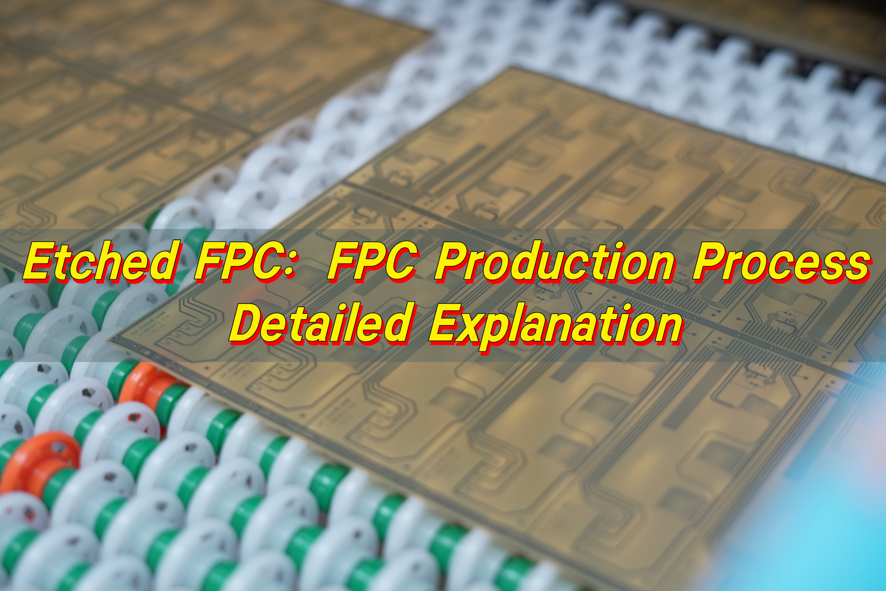
What Is Etched FPC?
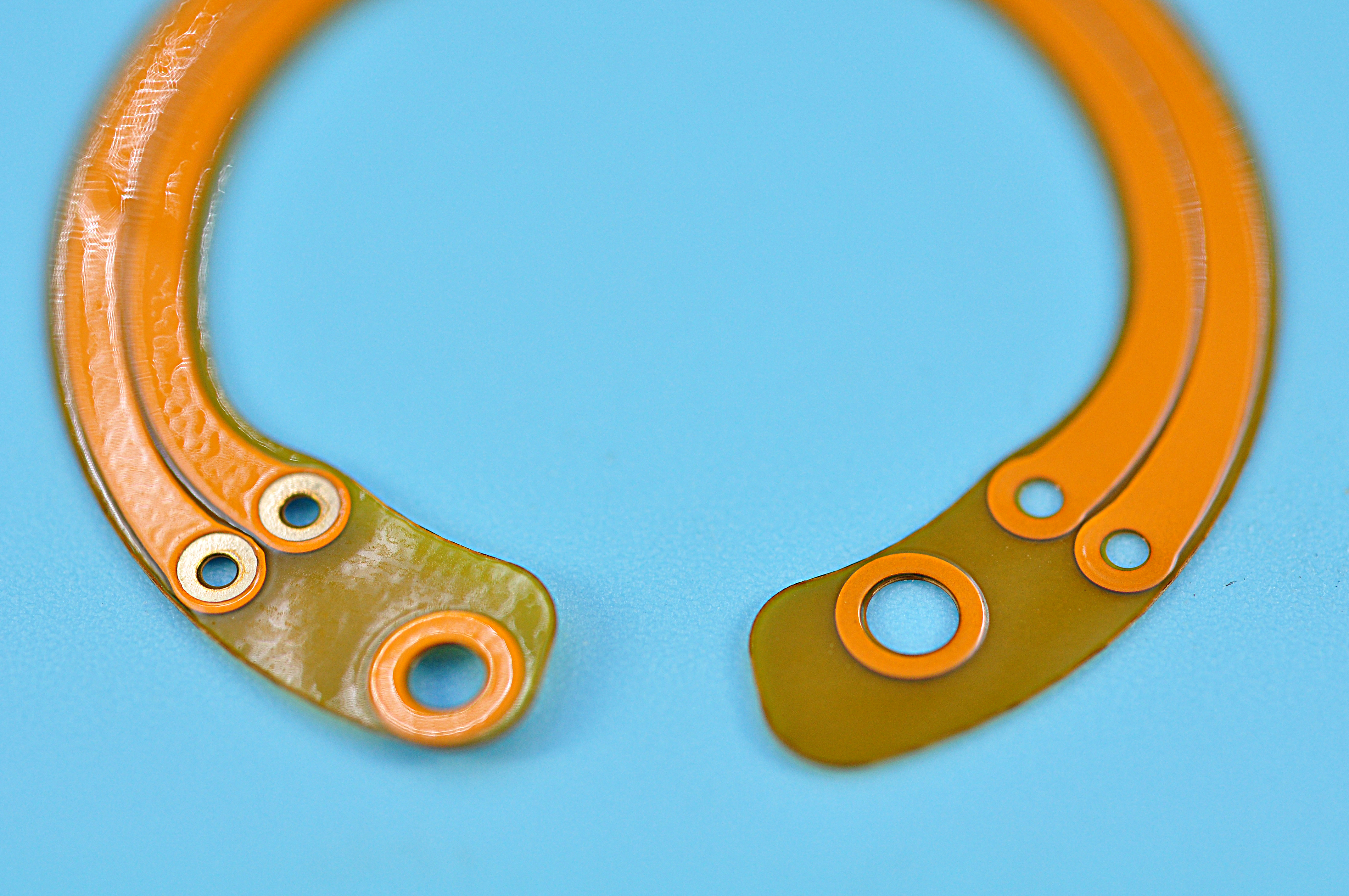
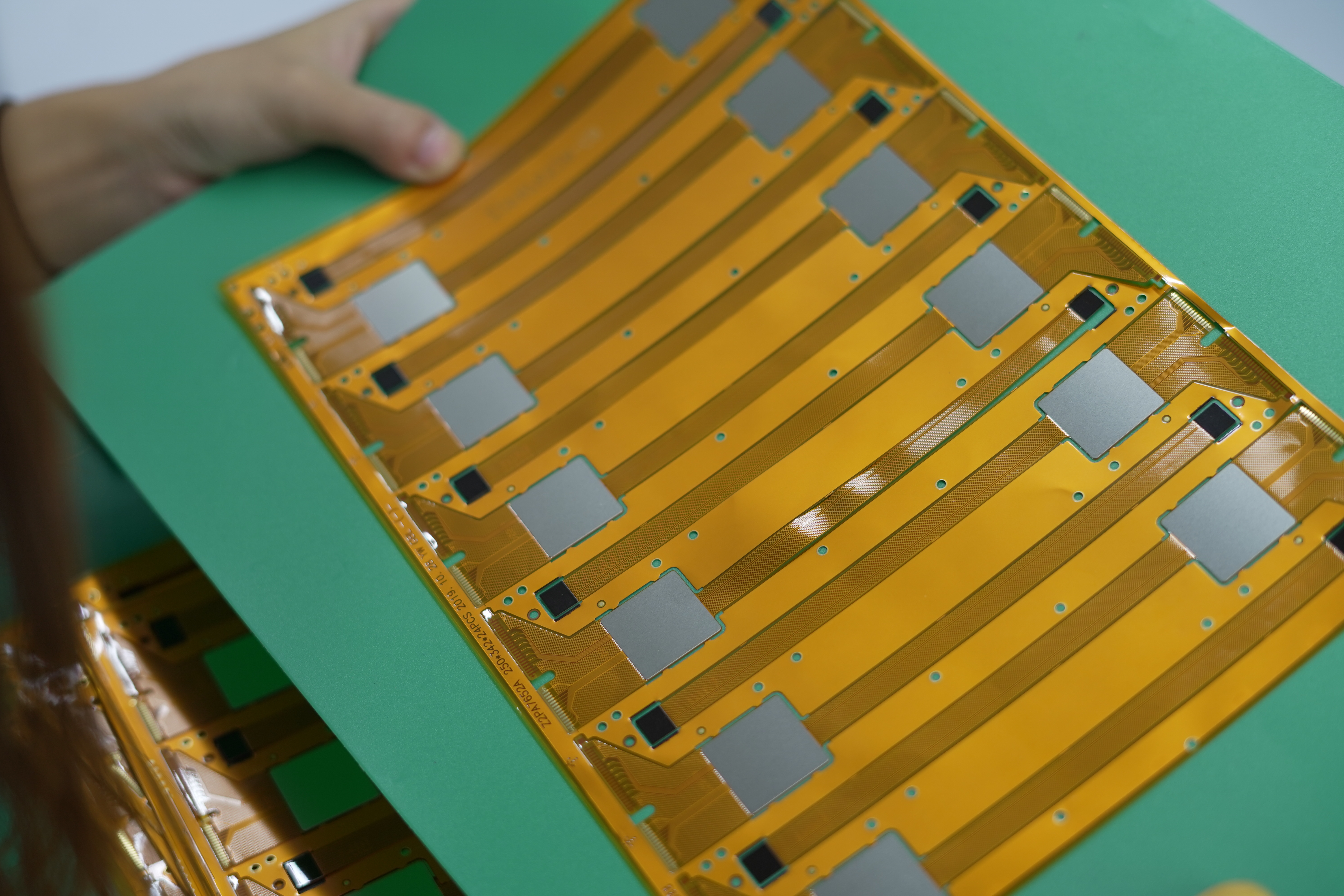
An etched FPC is a flexible printed circuit manufactured by removing unwanted copper from a copper-laminated film. The copper layer sits on a flexible base such as PI (polyimide). During production, only the copper that forms the circuit paths remains. The rest is dissolved through a controlled chemical reaction.
This etched pattern becomes the “wiring system” inside the flexible circuit. Each trace carries signals. Each pad connects components. Every turn, arc, branch, and wide section influences performance.
In simple terms, etching sculpts copper into the shape your electrical design requires.
- First, it enables thin and lightweight products. Because the copper is selectively removed, only the essential conductive areas remain. This leads to slimmer designs and easy bending.
- Second, it allows very precise circuit paths. Modern etching can form traces as narrow as 20–30 microns with tight tolerances.
- Third, it supports mass production. Once the artwork is set, every sheet follows the same pattern.
In many devices—wearables, sensors, medical tools, foldable products, cameras, automotive modules—the etched FPC plays a central role in size optimization and reliability.
Engineers often associate etched FPC with terms like:
- etched wire
- etched foil
- copper patterning
- chemical milling
All refer to the same core idea: shaping copper through controlled removal.
What Is the Manufacturing Process of FPC?
The FPC manufacturing process transforms copper-clad polyimide into flexible circuits through cleaning, imaging, etching, protection, shaping, and final testing.
- Base Material Preparation: Start with copper-clad polyimide (PI) film as the base material.
- Surface Cleaning: Clean the copper surface to remove dust, oil, and oxidation.
- Photoresist Application: Apply photoresist film to prepare for imaging.
- Image Exposure: Transfer the circuit pattern onto the resist through UV exposure.
- Resist Development: Develop the resist to reveal the copper that needs to be removed.
- Copper Etching: Etchant dissolves the exposed copper. Etch away the unwanted copper to form the final circuit traces.
- Resist Stripping: Strip the remaining photoresist to expose the clean copper pattern.
- Coverlay or Solder Mask Lamination: Add coverlay or solder mask to protect the copper traces.
- Stiffener and Adhesive Lamination: Stiffeners or reinforcement layers are added where mechanical strength is needed, such as connector areas.
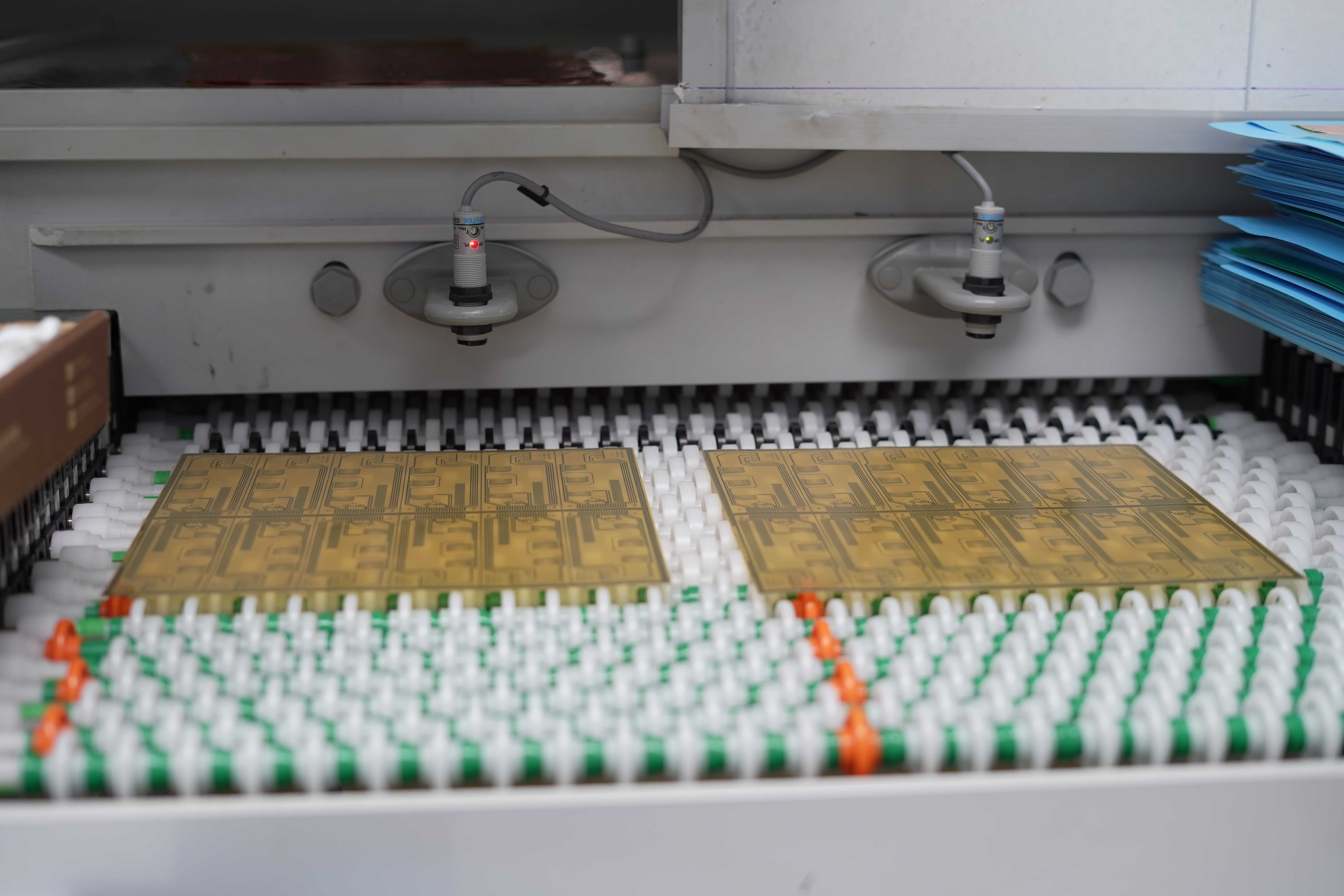
- Outline Cutting: Punch or laser-cut the final outline of the FPC.
- Electrical Testing: Each circuit is checked for opens, shorts, and signal continuity to ensure reliability.
- Final Inspection: The FPC undergoes full visual and dimensional checks before packaging and shipment.
What Is the Working Principle of Etching?
Etching uses a chemical solution that reacts with exposed copper. The reacting liquid dissolves the unwanted copper, leaving only the protected copper areas untouched. The protected copper is covered by a resist layer. This resist shields the areas that should remain as conductors.
We can divide the principle into three key steps:
- 1. Define the pattern
A film or photoresist is applied to the copper. This resist is patterned through exposure and development. The exposed areas match the final circuit routes. The covered parts block chemical attack.
- 2. Expose the unprotected copper to etchant
When the flex sheet enters the etching chamber, the etchant touches only the exposed copper. A chemical reaction begins immediately. The copper dissolves into the liquid.
The reaction rate depends on:
- Copper thickness
- Etchant temperature
- Flow speed
- Concentration
- Cleanliness of the surface
Control is crucial. Too fast, and edges become rough. Too slow, and the pattern shifts.
- 3. Strip the resist to reveal the final tracks
Once the unwanted copper has been removed, the resist layer is stripped away. What remains is the circuit pattern—the etched foil that forms your FPC wiring.
Every small parameter influences line width, spacing, edge smoothness, and undercut.
What Is Flexible Die-Cut Circuit (FDC) Technology?
Flexible Die-Cut Circuit (FDC) technology is a production method that shapes both the circuit pattern and the outline of the FPC through a die-cutting process. While etching focuses on copper removal, FDC focuses on cutting and shaping.
In other words:
- Etching defines the electrical pattern
- Die-cutting defines the physical shape
FDC technology gives engineers the freedom to design complex outlines—curved edges, mounting holes, windows, connectors, and multilayer features. Die-cutting tools are made based on the product’s final shape. These tools cut through all layers, including the coverlay and adhesive.
FDC adds precision to the physical design, while etching adds precision to the electrical structure. Together, they create a flexible circuit that feels seamless and well-engineered.
What Are the Disadvantages of Etching?
Etching is an exceptional process, but it does have a few limitations. They are not overwhelming.
The main challenges are:
- 1. Undercut
Undercut happens when the etchant dissolves copper sideways under the resist. It creates a wider gap than expected. This affects line accuracy.
- 2. Width tolerance
Very fine lines require strict control. If the copper thickness is high, achieving narrow traces becomes more complex.
- 3. Chemical management
Etching requires stable chemistry. Changes in temperature or concentration can shift the result. It demands frequent monitoring.
- 4. Waste treatment
Used chemical must be properly treated. This adds cost and responsibility.
BEST Technology’s FPC factory is well-equipped to handle these challenges. Equipment is more precise. Process control is more automated. Chemistry is more stable.
What Are the Types of Etching?
Etched FPC production involves different etching methods. The choice depends on copper thickness, precision needs, and production scale.
- 1. Acid etching
Acid etching uses acidic solutions to dissolve copper. The most common solution is cupric chloride. It is ideal for standard copper thickness and fine line work.
- 2. Alkaline etching
Alkaline etching works on thicker copper layers. It creates smoother edges for certain applications. It is used less for ultrafine lines, but it remains essential for heavy-copper FPC structures.
- 3. Wet chemical etching
This is the standard method used for most etched FPC. It uses liquid etchant sprayed on both sides. It offers high precision and can support mass production.
- 4. Dry etching (limited in FPC)
Dry etching uses plasma or gas. It is slow and expensive. It is rarely used in flexible circuit production except for special materials like thin film metal layers.
- 5. Differential etching
This method etches different areas at different speeds. It helps create patterns with variable copper thickness. It is used in advanced designs.
Acid spray etching remains the most popular for FPC because it balances speed, precision, and cost.
What Liquid Is Used for Etching FPC?
Several chemical liquids are used in etched FPC production. The most common is cupric chloride. It gives stable results and can be regenerated, making it efficient and sustainable.
Common etching liquids include:
- Cupric chloride: Most widely used, Good stability, Excellent for fine lines, Works well in spray systems
- Ferric chloride: Strong etching ability, Used for certain specialty films, Creates consistent pattern edges
- Ammoniacal etchant (ammonia-based): Good for thick copper, Offers fast etching rate, Requires tight control
The choice depends on:
- Copper thickness
- Line width
- Production volume
- Type of resist
- Equipment available
Cupric chloride remains the standard because it balances speed and precision. It helps create clean and smooth etched foil patterns.
How Long Does It Take to Etch an FPC?
Etching time depends on:
- Copper thickness
- Etchant concentration
- Temperature
- Spray pressure
- Agitation
- Equipment configuration
In most modern factories, the etching process is surprisingly fast.
Typical etching time ranges from: 30 seconds to 3 minutes
Thin copper (9–18 microns) etches quickly. Thicker copper takes longer. A high-flow spray system can reduce the time further.
However, etching is never rushed. The precision of the final circuit pattern matters far more than speed. Even a small change in timing may affect trace width.
Good process control ensures:
- Smooth sidewalls
- Tight tolerance
- Minimal undercut
- Uniform copper removal
In high-volume production, consistency matters the most. Etching time is kept stable from batch to batch. Automated monitoring systems measure concentration, temperature, and spray pressure to avoid fluctuations.
What Is the Problem With Etching FPC?
While etched FPC is highly reliable, the process has a few challenges that engineers monitor closely. These challenges are all surmountable, and BEST Technology is well-equipped to handle them.
- Undercut: This is the most common challenge. It happens when the etchant dissolves copper sideways. If not controlled, traces become thinner than expected.
- Over-etching: If etching continues too long, edges become rough. The pattern may shift. This is why timing must be precise.
- Under-etching: If etching stops too early, some copper remains. This may cause shorts or poor connection.
- Variations in copper thickness: Uneven copper coatings lead to uneven etching. High-end equipment solves this with better copper laminates and stable process lines.
- Resist issues: If the resist is applied unevenly, the pattern may not match the design.
- Chemistry balance: Chemistry must stay stable. If concentration shifts, the etch rate changes.
BEST Technology’s factories follow strict process controls to ensure consistent product quality.
Conclusion:
Etched FPC production is one of the most important steps in flexible circuit manufacturing. It shapes copper into precise pathways that carry signals in today’s most advanced products.
If you need expert support, professional advice, or reliable production for etched FPC, you can always reach us at: sales@bestpcbs.com