

What Is Electronic Component Failure?
When any part inside an electronic system stops working as expected, it’s called an electronic component failure. This could mean a capacitor no longer holds charge, a resistor burns out, or an integrated circuit malfunctions. Even one small faulty component can lead to major issues in the final product.
To find out why a component failed, engineers use a process called electronic component failure analysis. This process involves inspecting the part visually and electrically, identifying how and why the fault happened, and using that information to avoid similar problems in the future. It’s essential for quality assurance, product reliability, and cost control in any electronics-related business.

Types of Electronic Component Failure
Electronic components can fail in different ways depending on the stress they endure. Below are the four most common types:
1. Mechanical Failure
Mechanical failure happens when there is a physical breakdown of the component’s structure. Some failures are often caused by vibration, improper handling, or dropping a device. In mobile or automotive electronics, this type of failure is especially common due to frequent movement. Common typical failures are including:
- Cracked solder joints
- Broken leads or pins
- Fractured PCB substrates
- Loose connectors due to vibration
You might notice components that are no longer connected properly to the board or parts that move when touched. Visual inspection often reveals cracks or loosened parts caused by physical force.
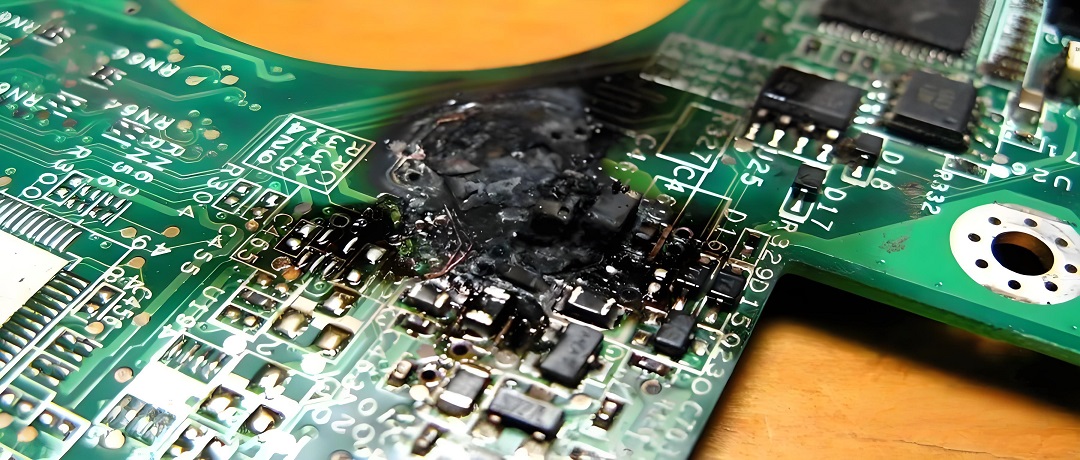
2. Thermal Failure
All electronic parts generate some heat when they operate. However, if the heat is not controlled properly, components can overheat and become damaged. This is known as thermal failure.
For example, semiconductors like transistors and integrated circuits are sensitive to high temperatures. When they get too hot, their internal structure may break down, leading to permanent damage.
3. Aging Failure
Components have a natural lifespan. Over time, materials degrade, and the component can no longer perform its function correctly. This is called aging failure.
Electrolytic capacitors are well-known for this issue—they tend to dry out after years of use, causing them to lose their ability to hold charge. Similarly, solder joints can crack after repeated heating and cooling cycles (called thermal cycling), leading to poor connections. In addition to this, typical aging failures also including:
- Metal fatigue in solder joints
- Battery capacity reduction
- Deteriorated dielectric layers
4. Packaging Failure
Electronic components are enclosed in packaging to protect the inner materials. If the packaging is flawed or gets damaged during use, it may expose the component to moisture, dust, or chemicals.
For instance, water vapor may seep through a cracked chip case and cause corrosion inside. This is especially risky in humid or corrosive environments. Packaging failure is often seen as cracking, blistering, or delamination of the part’s outer shell.
Causes of Electronic Component Failure
To solve problems effectively, it’s important to understand the root causes behind failures. Below are the most common causes engineers encounter during electronic component failure analysis:
1. Overvoltage and Overcurrent
Every electronic component has a maximum voltage and current rating. Exceeding these limits can damage the internal structure, often leading to immediate failure. For example, sending too much current through a resistor can cause it to overheat and burn. Applying excessive voltage to a capacitor can cause it to explode or leak.
2. Poor Soldering or Manufacturing Defects
Faulty assembly techniques can lead to short circuits, intermittent connections, or component movement. Cold solder joints—where the solder didn’t melt completely—can crack over time.
If a component is misaligned or not soldered properly to all its pads, it may not function or may fail under mechanical stress. These defects are usually caught through visual inspection or X-ray analysis.
3. Electrostatic Discharge (ESD)
Static electricity may not hurt humans, but it can destroy sensitive components like MOSFETs and ICs instantly. Even a small ESD event can damage internal junctions, creating invisible faults that show up later during use.
4. Environmental Stress
Moisture, dust, salt, or chemicals in the air can corrode metal parts, especially in outdoor or industrial environments. Extreme temperatures or frequent thermal cycling can stress materials, causing them to crack or delaminate.
5. Inadequate Design or Component Selection
Using the wrong part for the job—such as a low-voltage capacitor in a high-voltage section—can lead to early failure. Similarly, ignoring derating rules (operating parts near their limit) can reduce lifespan dramatically.
How to Check Faulty Electronic Components?
When a device isn’t working, checking the components one by one is a logical step. Here’s how to do that effectively:
1. Visual Inspection
The first step is always to look carefully. Use a magnifying glass or microscope if needed. There are some signs can be checked directly if components get failure. Look for:
- Burn marks or discoloration
- Cracks or broken legs
- Bulging or leaking capacitors
- Lifted or cracked solder joints
- Warping or melting
2. Smell
Burnt electronic parts release a strong smell. If a section of the board smells like burnt plastic or metal, you’re probably close to the damaged part.
3. Touch Test (with Caution)
Once the power is OFF and the board is safe to handle, you can gently feel components. If one feels much hotter than the rest, it may be failing. Never touch live circuits, and use caution even when power is removed—capacitors may still hold a charge.
4. Comparison Method
If you have an identical working device, compare it with the faulty one. Swapping parts one by one can help isolate which component isn’t working.
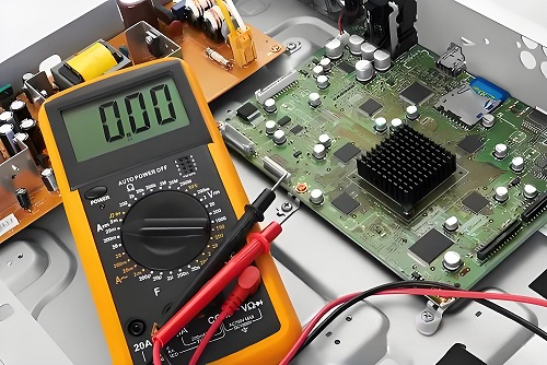
5. Multimeter Testing
A digital multimeter is your best tool. You can test for open circuits, shorts, or measure resistance, voltage, and continuity. We’ll explain this in the next section in detail.
How to Prevent Electronic Component Failures?
While you can’t prevent all failures, many of them can be avoided with good design, handling, and maintenance practices.
- Always source your components from reputable suppliers. Cheap or counterfeit parts are far more likely to fail.
- Avoid pushing components near their max voltage, current, or temperature limits.
- Add surge protection (like TVS diodes or fuses) where needed.
- Use appropriate PCB layout techniques for signal integrity and thermal control.
- Use anti-static wrist straps and mats when handling sensitive parts.
- Store components in anti-static bags or boxes.
- Avoid touching component pins directly.
- Good soldering practices and correct part orientation go a long way. Automated optical inspection (AOI) and in-circuit testing (ICT) help ensure quality during production.
- For circuits exposed to moisture or dust, apply conformal coating or potting material to prevent corrosion and shorts. Use enclosures with proper IP ratings if the device will be outdoors.
- Use heatsinks, thermal vias, fans, or thermal pads to keep parts cool. High temperatures shorten component life more than almost any other factor.
How to Test Electronic Components with a Multimeter?
A multimeter is one of the most useful tools for checking components, it can be tested various parts, here is how to test:
1. Testing Capacitors
- Discharge the capacitor before testing.
- Set the multimeter to capacitance mode (if available).
- Connect probes to the leads.
A large difference between the reading and rated value suggests aging or failure.
Note: If your multimeter lacks capacitance mode, you can test for short or open conditions using resistance mode.
2. Testing Diodes and LEDs
- Set the meter to diode test mode.
- Connect the red probe to the anode and the black to the cathode.
- A good diode should show a forward voltage drop (~0.6–0.7V).
- Reversing the probes should show no reading.
LEDs can also be tested this way, and a faint light may even flash when tested in forward bias.
3. Testing Transistors
Bipolar junction transistors (BJTs) can be tested by checking base-emitter and base-collector junctions like diodes.
- Use diode mode.
- Test base-to-emitter and base-to-collector—each should show ~0.6V in forward bias.
- Reversed probes or collector-to-emitter should show no conduction.
- If you get readings in all directions, the transistor may be shorted.
4. Testing ICs
Integrated circuits are difficult to test with just a multimeter. You usually need to power the board and check input/output signals or use dedicated IC testers.
FAQs
1. What is the first sign of electronic component failure?
Burn marks, strange smells, or malfunctioning behavior are common early signs of component issues.
2. How do you test an electronic component without removing it from the circuit?
You can test many components in-circuit using a multimeter, but readings may be affected by parallel components.
3. How often should electronics be inspected for aging components?
Critical systems should be checked annually, while consumer devices may only need service after several years.
4. What is the role of derating in preventing failures?
Derating means operating components below their maximum limits to reduce stress and increase reliability.
5. Can failure analysis improve future product design?
Yes, analyzing failed parts helps engineers refine design, choose better materials, and improve overall durability.
If you’re working on a repair or want to improve your product’s reliability, proper electronic component failure analysis is a valuable step. Want help with failure diagnostics or reliable PCB assembly? Reach out to EBest Circuit (Best Technology) — your trusted partner for high-quality, certified PCB and PCBA solutions.
We follow strict quality control with quality control systems, and offer full traceability for manufacturing, report, datasheet… If you want to do PCB assembly or components sourcing, welcome to reach us at sales@bestpcbs.com.