

Looking for COB LED PCB solutions? Explore its benefits, applications, assembly, production, manufacturer selection, and COB vs. DOB differences in this guide.
EBest Circuit (Best Technology) excels as a COB LED PCB manufacturer with 24-hour rapid prototyping for design validation, accelerating product development cycles. Our vertically integrated production combines automated die bonding (±5µm precision) and advanced thermal management (ceramic substrates with 5-8 W/m·K conductivity) to ensure <2% defect rates, validated through LM-80 lifespan tests and thermal cycling (-40°C to +125°C). Leveraging economies of scale, we deliver cost-optimized solutions without compromising IPC Class 3 standards, achieving 15-20% price advantages versus competitors. Real-time production tracking and AI-driven AOI systems guarantee 99.9% on-time delivery for bulk orders. Technical support includes free DFM analysis for high-density layouts (up to 120 chips/cm²) and post-sale failure diagnostics. Partner with us for agile, high-performance COB LED PCBs. Welcome to contact us if you’re interested in our service: sales@bestpcbs.com.
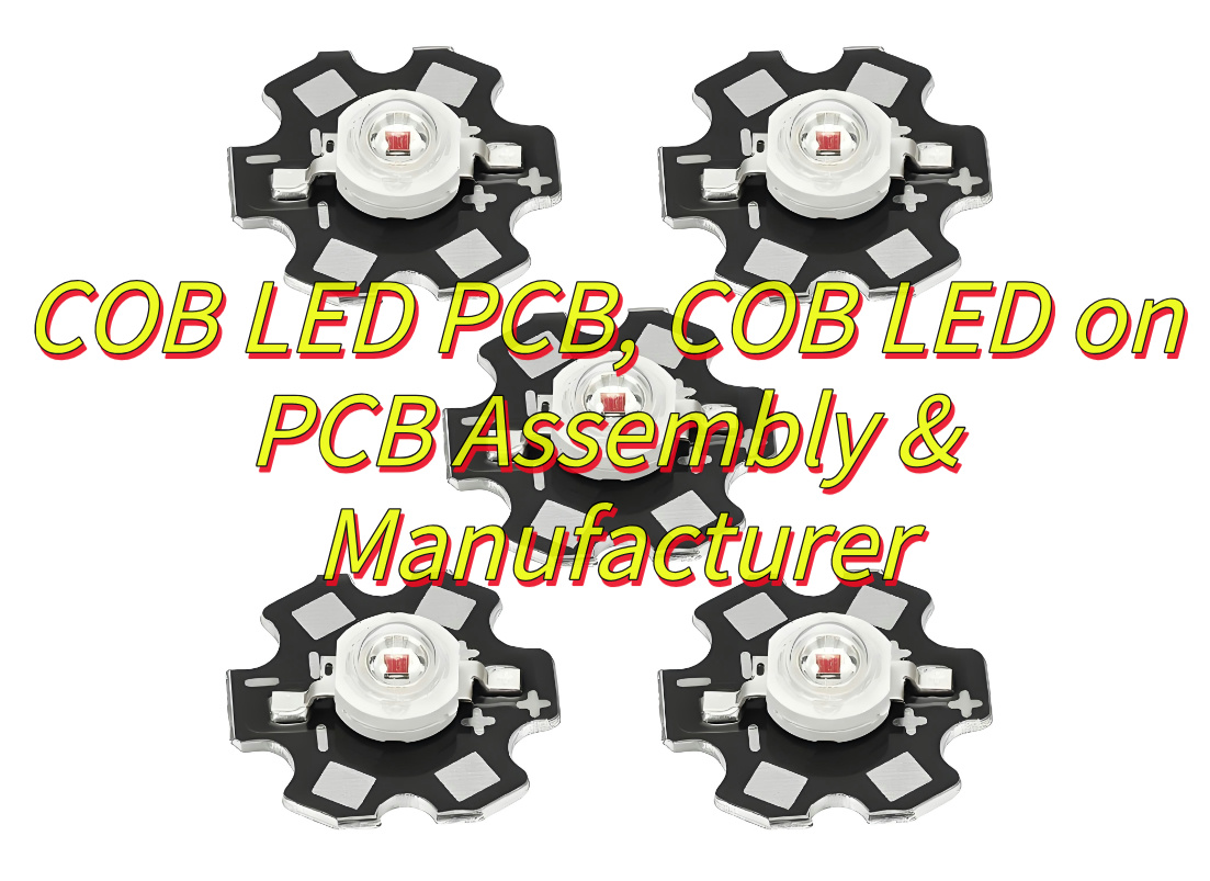
What Is A COB LED PCB?
A COB LED PCB is an integrated technology where LED chips are mounted directly onto a printed circuit board (PCB) substrate, bypassing traditional packaging components like plastic housings or wire leads. This approach bonds multiple LED chips to the PCB using conductive adhesives or solder, then encapsulates them with protective materials such as silicone or epoxy resin to enhance durability and optical performance. By eliminating intermediary packaging layers, COB LED PCBs achieve higher component density, improved heat dissipation through direct contact with the PCB’s copper traces, and uniform light distribution with wide viewing angles. They are widely used in high-brightness displays, commercial lighting, and industrial systems requiring compact, energy-efficient designs. Their robust structure minimizes failure points, supporting long-term reliability in applications like video walls, automotive lighting, and smart devices. Market analyses project significant growth in COB adoption, particularly in Mini/Micro LED applications, due to advancements in precision manufacturing and thermal management innovations.
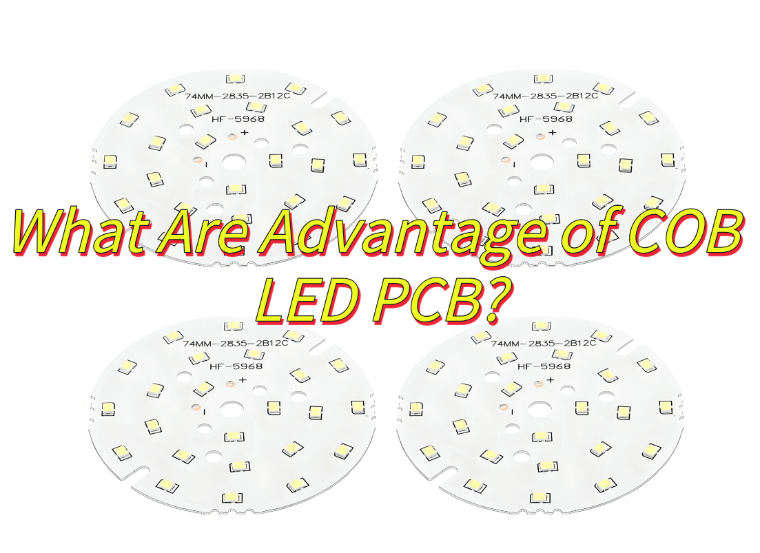
What Are Advantage of COB LED PCB?
Advantages of COB LED PCB
Enhanced Thermal Management
- Direct Chip-to-Board Bonding: LED chips are mounted directly on the PCB, eliminating the need for traditional wire bonds and reducing thermal resistance. This design enables efficient heat dissipation through the PCB substrate, lowering junction temperatures by 10–15°C compared to SMD LEDs.
- Metal-Core PCBs (MCPCBs): Many COB LED PCBs use aluminum or copper-based MCPCBs, which provide superior thermal conductivity (2–5 W/m·K) and extend LED lifespan to over 100,000 hours.
Superior Optical Performance
- High Brightness and Uniformity: COB’s chip-dense arrangement minimizes light loss and achieves >95% light extraction efficiency. For example, COB FPC soft boards used in commercial lighting deliver 15–20% higher luminous flux than conventional designs.
- Ultra-Fine Pixel Pitch: COB supports pixel pitches as tight as P0.4, enabling 4K/8K displays with 160° viewing angles and HDR10+ compatibility.
Compact Design and Space Efficiency
- Reduced Form Factor: By integrating multiple chips into a single module, COB LED PCBs reduce module thickness by 40–60%. Flexible COB variants (e.g., polyimide-based FPCs) enable 360° bending for applications like curved displays or wearable devices.
- Lightweight Construction: Thinner PCBs (0.4–1.2 mm) and elimination of bulky brackets cut module weight by up to 70%, lowering installation and transportation costs.
Robust Reliability and Durability
- IP65+ Protection: Encapsulation with epoxy resin or silicone gel shields against moisture, dust, and vibrations. COB displays achieve 4H surface hardness and withstand 10,000+ flex cycles without performance degradation.
- Low Failure Rates: Direct bonding and fewer components reduce solder joint fatigue, resulting in <0.01% dead pixel rates over 5 years of continuous use.
Design Flexibility and Customization
- Shape Adaptability: COB supports custom geometries (e.g., circular, triangular) for architectural lighting or retail signage. Dynamic RGBW configurations enable 16 million color combinations via PWM tuning.
- Smart Integration: COB FPC boards embed drivers, sensors, and IoT modules for applications like smart streetlights or interactive displays.
Cost-Efficiency and Scalability
- Streamlined Manufacturing: COB reduces assembly steps by 30% by eliminating individual chip packaging. Bridgelux’s Vero Series COB modules achieve 120 lm/W efficacy at 0.10–0.20 per lm, lowering BOM costs by 25%.
- Energy Savings: High-efficiency COB designs (e.g., Cree’s CXA3070) consume 40% less power than HID lamps, offering ROI within 2–3 years for industrial projects.
Environmental and Safety Compliance
- Recyclable Materials: Lead-free solder and halogen-free substrates meet RoHS/REACH standards.
- Low Glare and Flicker: Diffused light output minimizes eye strain, making COB suitable for offices (UGR <19) and healthcare facilities.
What Are Application of COB LED PCB?
Applications of COB LED PCB:
High-Resolution Displays
- Control Rooms & Broadcast Studios: COB LED PCBs enable ultra-fine pixel pitches (e.g., P0.4–P1.0) and support 4K/8K resolutions with HDR10+ compatibility. Their 160° viewing angles and 1,000,000:1 contrast ratios make them ideal for surveillance centers and TV studios.
- Commercial Signage: Retail stores and airports use COB displays for vibrant, seamless visuals with 95% light extraction efficiency and 15–20% higher luminous flux than conventional designs.
Architectural & Design Lighting
- Curved Installations: Flexible COB LED PCBs (e.g., polyimide-based FPCs) conform to irregular surfaces like domes or columns, with bending radii as tight as 5mm.
- Recessed Lighting: Thermal-enhanced COB modules (e.g., aluminum-core PCBs) reduce junction temperatures by 10–15°C, ensuring longevity in high-ceiling applications.
Automotive & Transportation
- Interior Displays: COB LED PCBs power dashboard clusters and infotainment systems, meeting AEC-Q102 standards for vibration resistance (-40°C to 125°C operation).
- Exterior Lighting: High-power COB modules (e.g., 100W+ designs) are used in headlights and brake lights, offering 40% lower power consumption than HID lamps.
Medical & Industrial Equipment
- Surgical Lights: COB’s 95+ CRI and 16-bit grayscale ensure accurate color rendering in operating rooms.
- Factory Automation: IP65-rated COB displays withstand harsh environments (dust, moisture, and 24/7 operation).
Consumer Electronics
- Wearable Devices: Flexible COB FPC boards enable 360° bending for smartwatches and AR glasses, with thicknesses reduced by 40–60%.
- Gaming Monitors: High-density COB panels achieve 360Hz refresh rates and 0.5ms response times for competitive gaming.
Entertainment & Events
- Stage Backdrops: Lightweight COB video walls (e.g., 7.9mm pitch) support rapid assembly/disassembly for touring concerts.
- Interactive Floors: Pressure-sensitive COB modules with 200kg/cm² load capacity create immersive experiences in museums and exhibitions.
Smart City Infrastructure
- Digital Signage: Outdoor COB displays (e.g., 10,000 cd/m² brightness) remain visible under direct sunlight, with IP68 protection for all-weather use.
- Traffic Management: COB-based variable message signs (VMS) update in real-time, with 10-year MTBF ratings.
Specialized Applications
- Aerospace: Radiation-hardened COB LED PCBs operate in satellites, withstanding 1,000 Gy radiation doses.
- Marine Navigation: Corrosion-resistant COB modules meet MIL-STD-810G standards for saltwater exposure.

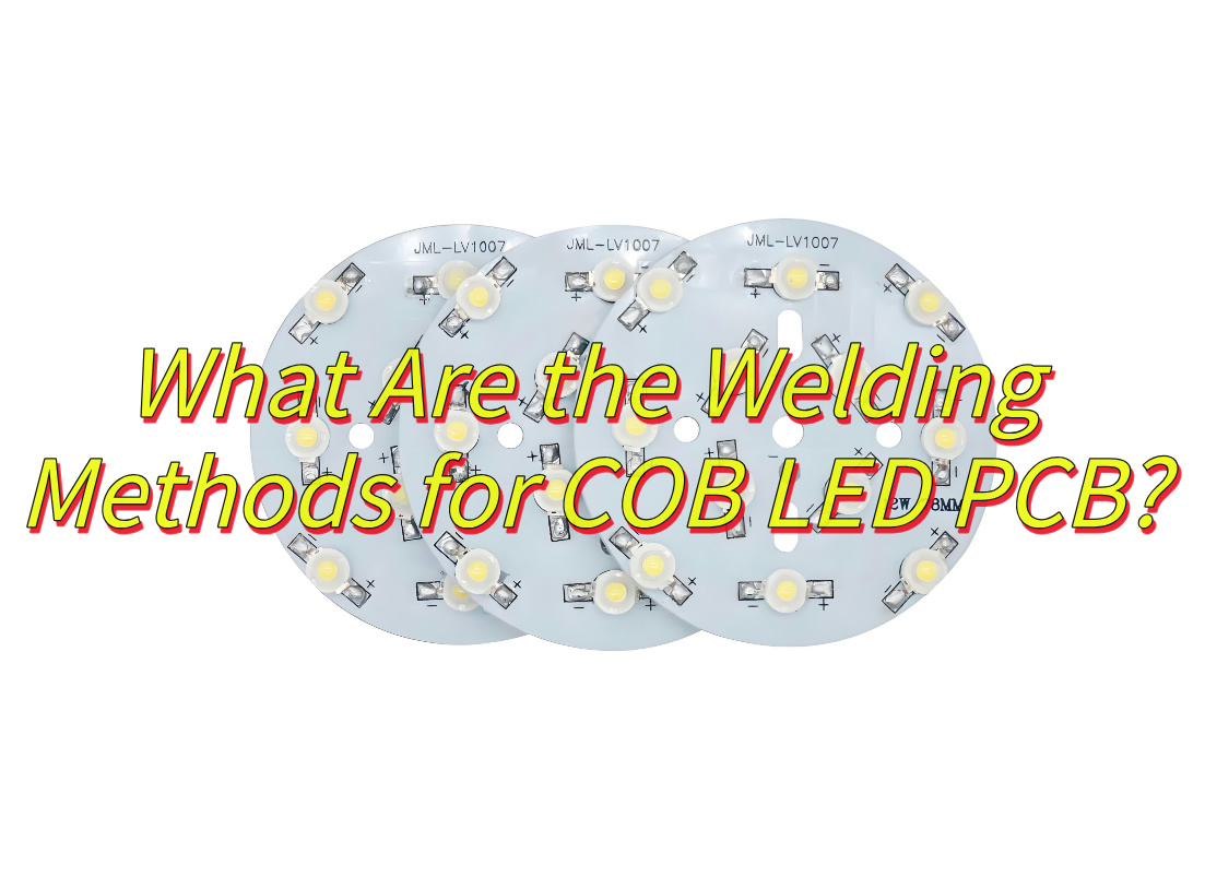
What Are the Welding Methods for COB LED PCB?
Welding methods for COB LED PCB:
Thermocompression Bonding
- Process: LED chips are aligned on the PCB and bonded using heat (180–250°C) and pressure (5–15 MPa). This method eliminates the need for solder, reducing thermal stress.
- Advantages: Ideal for flip-chip COB LED PCBs, achieving bond line thicknesses <5μm and shear strengths >20 N/mm².
- Applications: High-density displays (e.g., P0.6–P1.0 video walls) and automotive dashboards.
Laser Welding
- Process: A focused laser beam (e.g., 980nm diode) locally heats the PCB and chip electrodes, forming a metallurgical bond.
- Advantages: Enables precision welding for micro-LEDs (50–200μm) with minimal thermal impact (<5°C rise).
- Applications: Wearable devices (e.g., smartwatches) and medical endoscopes.
Ultrasonic Welding
- Process: High-frequency vibrations (20–40 kHz) generate friction at the chip-PCB interface, melting and bonding materials without external heat.
- Advantages: Solder-free, dust-resistant, and compatible with flexible COB FPC boards.
- Applications: Curved displays and retail signage.
Solder Reflow Welding
- Process: Solder paste is screen-printed onto PCB pads, chips are placed, and the assembly undergoes infrared or vapor-phase reflow (peak 240–260°C).
- Advantages: Cost-effective for mass production, with 99%+ yield rates.
- Applications: Industrial lighting and general-purpose displays.
Conductive Adhesive Bonding
- Process: Silver-filled epoxy or acrylic adhesives cure under UV light or heat (80–150°C), providing electrical and mechanical connections.
- Advantages: Low-temperature processing (prevents LED degradation) and 30% lighter than solder joints.
- Applications: Battery-powered devices (e.g., flashlights) and automotive interior lights.
Wire Bonding
- Process: Gold or aluminum wires (18–50μm) are bonded between chip pads and PCB traces using ultrasonic energy and pressure.
- Advantages: Established method for standard COB LED PCBs, with loop heights <0.3mm.
- Applications: Commercial signage and low-resolution displays.
Flip-Chip Bumping
- Process: Solder bumps are deposited on LED chips, which are then flipped and aligned to PCB pads for reflow.
- Advantages: Eliminates wire bonds, enabling 45% lower power consumption and 10% higher light extraction.
- Applications: Mini-LED backlights and high-end monitors.
What Are Manufacturing Process of COB LED PCB?
Manufacturing Process of COB LED PCB
COB (Chip-on-Board) LED PCB manufacturing involves integrating LED chips directly onto printed circuit boards through a series of precision-engineered steps. Below is a structured overview of the process, emphasizing technical rigor and industry best practices:
1. Material Preparation & Inspection
- LED Chip Sorting: LED chips undergo rigorous testing for brightness, wavelength (e.g., 450–460nm for blue chips), and forward voltage (VF). Chips are binned into grades to ensure uniformity in COB modules.
- PCB Cleaning: PCBs are cleaned using plasma or ultrasonic baths to remove oxide layers and contaminants, ensuring optimal adhesion for subsequent steps.
2. Die Attach (Chip Mounting)
- Expansion: LED wafers are mechanically expanded to separate chips for precise handling.
- Flux/Adhesive Dispensing: Solder paste (e.g., SnAgCu) or conductive epoxy is applied to PCB pads using stencil printing (tolerance: ±25μm).
- Pick-and-Place: Robotic systems place chips onto PCBs with ±10μm accuracy. For flip-chip COB, eutectic solder bumps (e.g., AuSn) align with PCB pads.
3. Reflow Soldering or Thermocompression Bonding
- Reflow: PCBs pass through infrared ovens (peak temperature: 245–260°C) to melt solder, forming intermetallic joints (IMC thickness: 1–3μm).
- Thermocompression: For flip-chip COB, heat (180–250°C) and pressure (10–15 MPa) bond chips without solder, achieving void-free connections.
4. Wire Bonding
- Aluminum/Gold Wire Bonding: Ultrasonic wedge bonders connect chip electrodes to PCB traces using 18–50μm wires. Key parameters:
- Ultrasonic Power: 80–120mW (Al), 40–60mW (Au).
- Loop Height: 0.1–0.3mm (minimizes arc-induced stress).
- Quality Check: Bond shear strength >10g (Al), >15g (Au); ball bond diameter tolerance: ±10%.
5. Encapsulation
- Global Top Coating: Silicone or epoxy is dispensed via jetting systems (e.g., Nordson ASYMTEK) to protect chips and wires.
- Curing: Thermal chambers (150°C, 1–2 hours) harden the resin, achieving 90% light transmission and >95 Shore D hardness.
6. Testing & Quality Control
- Electrical Testing: High-precision probes measure IV curves, VF (±1%), and ESD withstand (>2kV).
- Optical Inspection: 2D/3D AOI systems detect dead pixels, color shifts (Δu’v’ <0.003), and luminance non-uniformity (<5%).
- Reliability Trials: Thermal cycling (-40°C to 125°C, 500 cycles) and 85°C/85% RH tests ensure 10,000+ hours MTBF.
7. Final Assembly & Packaging
- Module Integration: COB PCBs are mounted on heat sinks (e.g., 6063 aluminum) using thermal interface materials (TIMs) with 2–5 W/m·K conductivity.
- Laser Marking: Serial numbers and bin codes are etched using UV lasers (355nm wavelength).
How to Assemble COB LED on PCB?
How to assemble COB LED on PCB:
1. Pre-Assembly Preparation
PCB Design:
- Use metal-core PCBs (MCPCBs) with copper layers (1–3 oz.) for thermal dissipation.
- Include thermal vias (0.2–0.5mm diameter) under LED positions to enhance heat transfer.
Component Selection:
- Choose LED chips matching voltage (VF) and wavelength (λ) specifications.
- Prepare solder paste (e.g., Sn96.5Ag3Cu0.5) or conductive epoxy for die attach.
2. Die Attach (Chip Mounting)
Flux/Adhesive Application:
- Dispense solder paste via stencil printing (±25μm tolerance) or apply conductive epoxy using a jetting system.
Chip Placement:
- Use a pick-and-place machine (±10μm accuracy) to position LED chips on PCB pads.
- For flip-chip COB, align eutectic solder bumps with PCB traces.
3. Bonding Process
Reflow Soldering:
- Pass PCBs through an infrared oven (peak temperature: 245–260°C) to melt solder and form intermetallic compounds (IMC).
- Monitor reflow profile to prevent solder bridging or voids (>95% fill rate required).
Thermocompression Bonding:
- Apply heat (180–250°C) and pressure (10–15 MPa) to bond flip-chips without solder.
- Ensure bond line thickness (BLT) <5μm for optimal thermal/electrical contact.
4. Wire Bonding (If Applicable)
- Wire Selection: Use aluminum (Al) wires (18–25μm) for cost sensitivity or gold (Au) wires (25–50μm) for reliability.
- Bonding Parameters: Set ultrasonic power (80–120mW for Al, 40–60mW for Au), bond force (40–60g), and loop height (0.1–0.3mm).
- Quality Check: Verify bond shear strength (>10g for Al, >15g for Au) and ball bond diameter (±10% tolerance).
5. Encapsulation
- Resin Dispensing: Apply silicone or epoxy globally using jetting systems (e.g., Nordson ASYMTEK) to protect chips and wires.
- Curing: Harden resin in thermal chambers (150°C, 1–2 hours) to achieve 90% light transmission and hardness >95 Shore D.
6. Testing & Inspection
- Electrical Testing: Measure IV curves, forward voltage (VF ±1%), and ESD withstand (>2kV) using automated test equipment (ATE).
- Optical Inspection: Use 2D/3D AOI systems to detect dead pixels, color shifts (Δu’v’ <0.003), and luminance non-uniformity (<5%).
- Reliability Trials: Conduct thermal cycling (-40°C to 125°C, 500 cycles) and 85°C/85% RH tests to validate 10,000+ hours MTBF.
7. Final Assembly
- Thermal Management: Attach COB modules to heat sinks (e.g., 6063 aluminum) using thermal interface materials (TIMs, 2–5 W/m·K conductivity).
- Laser Marking: Etch serial numbers and bin codes using UV lasers (355nm wavelength) for traceability.
How to Choose A Reliable COB LED PCB Manufacturer?
This is how to choose a reliable COB LED PCB manufacturer:
Technical Expertise & Innovation
- R&D Capabilities: Assess the manufacturer’s experience with COB-specific processes (e.g., flip-chip bonding, laser welding, micro-LED assembly). Look for patents in thermal management or high-density packaging.
- Material Knowledge: Verify their proficiency in selecting substrates (e.g., MCPCBs, flexible FPCs) and encapsulants (e.g., silicone vs. epoxy) for target applications (e.g., automotive, displays).
Quality Control & Certifications
- ISO Standards: Prioritize manufacturers with ISO 9001 (quality management), ISO 14001 (environmental), and IATF 16949 (automotive) certifications.
- Testing Facilities: Ensure in-house capabilities for reliability tests (thermal cycling, humidity resistance, ESD withstand) and optical measurements (luminance, CRI, spectral distribution).
Production Capacity & Equipment
- Automation Level: Check for advanced machinery (e.g., high-precision pick-and-place systems, laser bonders, AOI inspectors) to ensure consistency and yield rates >95%.
- Scalability: Confirm the ability to handle prototypes (1–100 pcs) and mass production (10,000+ pcs/month) without compromising quality.
Customization & Design Support
- DFM Services: A reliable partner should offer design-for-manufacturing (DFM) feedback to optimize PCB layout, thermal vias, and solder mask clearances.
- Prototyping: Evaluate lead times (7–14 days for samples) and flexibility in accommodating design iterations.
Supply Chain & Material Sourcing
- Traceability: Ensure components (LED chips, PCBs, adhesives) are sourced from tier-1 suppliers with lot-level traceability.
- Compliance: Confirm adherence to RoHS/REACH regulations and conflict-free mineral policies.
Industry Experience & Portfolio
- Case Studies: Review past projects in your target sector (e.g., medical lighting, automotive dashboards). Look for references to pixel pitches (e.g., P0.6–P1.2) and power ratings (e.g., 50W–500W).
- Longevity: Manufacturers with 10+ years of COB experience are less likely to encounter process bottlenecks.
Customer Service & Support
- Responsiveness: Test communication channels for pre-sales inquiries and post-sales technical support.
- Warranty: Seek manufacturers offering 2–5-year warranties with clear RMA (return merchandise authorization) procedures.
Cost vs Value Analysis
- Pricing Structure: Compare quotes for NRE (non-recurring engineering) fees, tooling costs, and per-unit pricing. Avoid unusually low bids that may indicate compromised quality.
- Total Cost of Ownership: Factor in long-term reliability, energy efficiency, and maintenance savings.
What Is the Difference Between COB LED and DOB LED?
COB (Chip-on-Board) LED and DOB (Driver-on-Board) LED represent distinct approaches to LED integration, each with unique structural and functional characteristics. Below is a structured comparison:
Structural Design
- COB LED: LED chips are directly mounted on a PCB (COB LED PCB) using conductive adhesives or solder, followed by wire bonding or flip-chip bonding. The entire assembly is encapsulated in silicone or epoxy for protection.
- DOB LED: Integrates both LED chips and a driver circuit (e.g., constant current regulator) onto the same PCB, eliminating the need for an external driver and reducing component count.
Thermal Management
- COB LED: Relies on the thermal conductivity of the COB LED PCB (e.g., metal-core PCBs with 2–5 W/m·K) to dissipate heat from densely packed chips, achieving lower junction temperatures (ΔTj <15°C vs. ambient).
- DOB LED: Combines high-power LEDs and driver components on a single PCB, requiring careful layout optimization to prevent heat buildup near sensitive driver ICs.
Applications
- COB LED: Ideal for high-power lighting (e.g., streetlights, industrial high-bay fixtures), automotive headlights, and ultra-fine pixel pitch displays (e.g., P0.4–P1.2 video walls).
- DOB LED: Suited for smart lighting (e.g., IoT-enabled bulbs, tunable white lamps), consumer electronics (e.g., TV backlights, wearable devices), and compact designs prioritizing space efficiency.
Performance Metrics
- COB LED: Offers high efficiency (up to 180 lm/W theoretical), excellent reliability (>100,000 hours MTBF), and supports high-current operation (1–10A) for luminous flux up to 20,000 lm.
- DOB LED: Provides cost savings (20–30% lower BOM costs) but with slightly lower efficiency (130–150 lm/W) due to driver-related losses.
Design Flexibility
- COB LED: Highly customizable via PCB layout adjustments (e.g., thermal vias, copper traces), enabling tailored thermal and optical performance.
- DOB LED: Limited by space sharing between LEDs and driver components, often requiring standardized form factors (e.g., T8 tubes, A19 bulbs).
Failure Modes
- COB LED: Primary risks include chip delamination, wire bond fatigue, and phosphor degradation, mitigated by advanced encapsulation techniques.
- DOB LED: Vulnerable to driver IC overheating, electrolytic capacitor aging, and EMI noise, necessitating rigorous EMC testing and thermal management.
Trends
- COB LED: Advancing toward micro-LED technologies (<50μm chips) and flexible substrates (e.g., polyimide FPCs).
- DOB LED: Integrating wireless controls (Bluetooth/Zigbee) and AI-driven features for smart lighting applications.
In conclusion, that’s all about COB LED PCB’s benefits, applications, assembly, production, manufacturer selection, and COB and DOB differences. If you have any issues about COB LED PCB, please leave a message below this blog.