

What makes CCPD XR495 007 V4.0 panel PCB stand out in LED applications? This guide covers configurations, thermal management, soldering, and reliability solutions.
At EBest Circuit (Best Technology), we manufacture premium CCPD XR495 007 V4.0 panel PCBs and other metal core PCB with industry-leading capabilities that directly benefit your projects. Our advanced manufacturing process delivers 30% faster turnaround than competitors, helping you meet critical deadlines. Whether you need mass production or just one prototype for testing, we offer the same high-quality standards with no minimum order requirements. We maintain complete pricing transparency – you’ll never encounter hidden fees or unexpected charges. Our engineering team provides free DFM analysis to optimize your designs for performance and cost-efficiency. With IPC Class 3 certified production, automated optical inspection, and strict quality control, we guarantee reliable PCBs that outperform industry standards. Specializing in thermal management solutions for LED applications, our CCPD XR495 007 V4.0 panel PCBs feature superior heat dissipation and uniform brightness control. From automotive to industrial applications, we deliver robust solutions tailored to your exact specifications. Get a competitive quote today and experience the EBest Circuit (Best Technology) difference – where quality, speed and affordability meet. Contact our sales team now to discuss your project requirements: sales@bestpcbs.com.
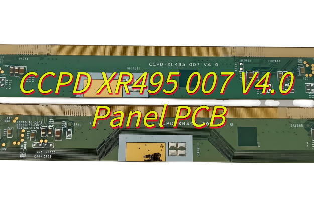
What Is CCPD XR495 007 V4.0 Panel PCB?
The CCPD XR495 007 V4.0 panel PCB represents an advanced iteration of panel PCB technology designed for high-performance applications. This version integrates enhanced thermal management and signal integrity features, making the CCPD XR495 007 V4.0 panel PCB particularly suitable for multilayer designs requiring consistent impedance control. With improved copper balancing and solder mask adhesion, the CCPD XR495 007 V4.0 panel PCB ensures reliable performance across extended operating cycles while maintaining compatibility with lead-free assembly processes. The design refinements in this iteration address common challenges in panelized PCB production, including warpage prevention and via reliability. Engineers working with high-density interconnects will find the material properties and manufacturing tolerances of CCPD XR495 007 V4.0 panel PCB adapted for precision applications where dimensional stability matters. Its standardized panelization approach simplifies fabrication while optimizing material utilization during mass production.
What Are Configurations of CCPD XR495 007 V4.0 Panel PCB?
Here are the configurations of CCPD XR495 007 V4.0 panel PCB:
- Layer Stackup Options: This panel PCB supports configurations from 8 to 24 conductive layers, with sequential lamination for high-density interconnects. Standard builds incorporate FR-4 Tg170 core materials complemented by low-loss prepregs optimized for signal integrity.
- Copper Weight Specifications: Available in 1oz to 4oz finished copper weights per layer. Heavy copper editions enable 40A continuous current handling on power planes while finer 0.5oz copper supports controlled impedance signal layers.
- Surface Finish Variants: Multiple finishing processes include ENIG (Electroless Nickel Immersion Gold) for fine-pitch components, immersion silver for RF applications, and HASL-LF for cost-effective solutions. Each finish undergoes rigorous solderability testing.
- Thermal Management Builds: Aluminum-core configurations feature thermally conductive dielectric layers, achieving 1.2°C/W thermal resistance. These specialized CCPD XR495 007 V4.0 panel PCB editions effectively dissipate heat from power components.
- Panelization Formats: Standard panels measure 18″x24″ with breakout tabs or 21″x24″ for V-score separation. Custom panel designs accommodate specific assembly fixtures, particularly for automotive radar modules requiring precise component placement.
- High-Frequency Material Integration: Hybrid constructions pair standard FR-4 with Rogers 4350B laminates in critical RF sections. This CCPD XR495 007 V4.0 panel PCB approach maintains stable Dk values (±0.05) across 5-77GHz frequency ranges.
- Specialty Thickness Profiles: Final board thickness ranges from 0.8mm for wearable devices to 3.2mm for industrial power converters. All configurations maintain consistent dielectric spacing tolerances within ±8%.
- Protection and Coating: Optional conformal coatings include acrylic for general use, silicone for high-temperature environments, and parylene for medical implants. Edge plating configurations provide additional corrosion resistance.
What Are Applications of CCPD XR495 007 V4.0 Panel PCB?
Here are the primary applications for CCPD XR495 007 V4.0 panel PCB:
- Telecommunications Infrastructure: The CCPD XR495 007 V4.0 panel PCB enables stable 5G millimeter-wave circuits due to its impedance-controlled dielectric layers. Base stations deploy these panels for beamforming antenna arrays where signal integrity above 24GHz becomes essential.
- Industrial Power Electronics: Motor controllers and uninterruptible power supplies benefit from this PCB’s thick copper variants. Specifically, CCPD XR495 007 V4.0 panel PCB configurations tolerate sustained 150A surges while maintaining thermal stability through rapid cycling events.
- Medical Diagnostic Systems: Advanced imaging equipment utilizes this standard for low-noise sensor interfaces. The microvia technology within CCPD XR495 007 V4.0 isolates sensitive analog components from digital interference in MRI machines and digital X-ray detectors.
- Automotive Control Units: Electric vehicle power management modules implement this panel PCB for vibration resistance. Its thermal cycling endurance ensures reliable operation in battery management systems exposed to -40°C to 160°C temperature swings.
- Aerospace Avionics: Flight control systems require the certified material traceability inherent in this standard. Furthermore, CCPD XR495 007 V4.0 panel PCB assemblies pass rigorous altitude testing for cabin pressure instrumentation without dielectric breakdown.
- High-Intensity Lighting Systems: Thermal management editions with metal cores manage 200W+ LED clusters efficiently. These specialized CCPD XR495 007 V4.0 versions maintain junction temperatures below 85°C in stadium lighting arrays.
- Robotics Motion Hardware: Multi-axis controllers leverage the 24-layer configurations for distributed processing. The panelization scheme provides necessary rigidity during high-G maneuvers while preserving signal timing across servo networks.
How to Manage Heat Dissipation in CCPD XR495 007 V4.0 Panel PCB Design?
Optimized heat dissipation strategies for CCPD XR495 007 V4.0 panel PCB design:
- Component Placement: Spread high-power components (e.g., voltage regulators, power transistors) evenly to avoid localized heating on the CCPD XR495 007 V4.0 panel PCB. Keep heat-sensitive parts (e.g., analog sensors) isolated to prevent thermal interference.
- Thermal Vias: Add dense thermal via arrays under heat sources to conduct heat to inner copper layers. Use 0.3mm vias with 0.5mm spacing for efficient vertical cooling without signal integrity issues.
- Copper Pour Expansion: Increase copper areas near hot components to spread heat laterally. Connect these zones to heat spreaders or chassis points using thermal interface materials to reduce peak temperatures.
- Material Selection: Choose substrates like aluminum-backed FR4 or ceramic-filled laminates for better thermal conductivity. Pair with low-resistance solder masks to avoid insulating heat on the PCB surface.
- Airflow Channels: Design trace routes to create airflow paths aligned with fans or natural convection. Avoid blocking ventilation zones with components in enclosed systems.
- Thermal Simulation: Use CFD tools to model heat distribution on the CCPD XR495 007 V4.0 panel PCB under extreme loads. Validate with infrared imaging and adjust layouts based on test results.
- Power Domain Isolation: Separate high-current and low-power sections using guard traces and ground planes. This minimizes thermal crosstalk and improves signal stability.
- Component Packages: Select SMD packages with exposed thermal pads or heat slugs. Ensure direct contact with copper pours for efficient conductive cooling.
How to Achieve Uniform Light Brightness For Multi-Color CCPD XR495 007 V4.0 Panel PCB?
Below are actionable strategies to optimize brightness uniformity of multi-color CCPD XR495 007 V4.0:
- LED Binning and Selection – Partner with suppliers to source LEDs from the same brightness and color bin. This minimizes inherent variations in luminous intensity and chromaticity, ensuring each LED on the CCPD XR495 007 V4.0 panel PCB performs identically. Doing so reduces the need for excessive post-production calibration and guarantees visual consistency.
- Current Matching Circuit Design – Implement precision current regulators for each LED channel. By maintaining identical current levels across all LEDs, you prevent overdriving some pixels while underpowering others. This approach extends LED lifespan and preserves brightness consistency, even as the CCPD XR495 007 V4.0 panel PCB ages.
- Optimized PCB Layout – Arrange LEDs in a staggered or matrix pattern to blend colors evenly. Avoid clustering LEDs of the same hue, as this creates visible “hotspots” or color tints. A well-planned layout ensures smooth color transitions and eliminates perceptible brightness variations.
- Diffuser and Light Guide Integration – Incorporate optical-grade diffusers or light guide plates (LGPs) above the LED array. These components scatter light uniformly, masking minor LED discrepancies and creating a cohesive visual output. For the CCPD XR495 007 V4.0 panel PCB, this step is particularly effective in eliminating angular brightness deviations.
- Thermal Management Synergy – Leverage the PCB’s thermal dissipation design to maintain stable operating temperatures. Uneven heating can cause LEDs to drift in brightness or color over time. By integrating heat-spreading copper pours and thermal vias, you ensure all LEDs perform within their optimal temperature range, preserving long-term uniformity.
- Pre-Production Calibration – Conduct individual pixel-level brightness calibration during manufacturing. Use spectroradiometers to measure and adjust each LED’s output, compensating for minor variations. This process guarantees the CCPD XR495 007 V4.0 panel PCB meets strict brightness uniformity standards before deployment.
- Aging and Drift Compensation – Include firmware that dynamically adjusts LED drive currents based on real-time performance data. This compensates for gradual brightness decay or color shifts, ensuring the CCPD XR495 007 V4.0 panel PCB maintains visual consistency throughout its service life.
- Environmental Robustness Testing – Validate the design under extreme temperatures, humidity, and voltage fluctuations. Identify and rectify conditions that cause uneven brightness degradation, ensuring reliable performance in diverse real-world scenarios.
How to Choose the Best Surface Finish For Reliable LED PCB Soldering?
- Evaluate Environmental Exposure: If the CCPD XR495 007 V4.0 panel PCB will operate in humid, corrosive, or high-temperature environments, prioritize finishes like ENIG (Electroless Nickel Immersion Gold) or ENEPIG (Electroless Nickel Electroless Palladium Immersion Gold). These offer superior corrosion resistance and prevent oxidation-related soldering issues.
- Consider LED Pitch and Density: For fine-pitch LED arrays, choose finishes with exceptional planarity, such as Immersion Silver or OSP (Organic Solderability Preservatives). These minimize solder bridging and ensure consistent wetting across closely spaced pads on the CCPD XR495 007 V4.0 panel PCB.
- Assess Long-Term Reliability Needs: Applications requiring 10+ years of service life benefit from ENIG or ENEPIG, which resist tarnishing and maintain solderability over time. Avoid HASL (Hot Air Solder Leveling) for LED PCBs, as its uneven surfaces may compromise fine-pitch solder joints.
- Balance Cost and Performance: For cost-sensitive projects, Immersion Tin or OSP provide acceptable performance at lower prices. However, note that OSP has a shorter shelf life and requires strict humidity control during storage to prevent degradation.
- Test for Thermal Cycle Resistance: LED PCBs often endure repeated thermal expansion. ENEPIG excels here due to its palladium barrier layer, which prevents nickel corrosion during thermal cycling. This finish is ideal for the CCPD XR495 007 V4.0 panel PCB in applications with frequent on/off cycles.
- Verify Compatibility with Lead-Free Soldering: If using lead-free processes, opt for Immersion Silver or ENIG. These finishes withstand the higher reflow temperatures required for lead-free alloys without degrading solder joint integrity.
- Address Signal Integrity Requirements: For LED PCBs with high-speed data lines, Immersion Silver offers a flat, conductive surface that minimizes signal loss. Avoid finishes like HASL, which can introduce uneven surfaces and impedance discontinuities.
- Consult with Your Contract Manufacturer: Work closely with your PCB fabricator to validate finish selection. They can provide samples of the CCPD XR495 007 V4.0 panel PCB with different finishes for solderability testing, ensuring alignment with your production equipment and processes.
What Causes Soldering Defects in CCPD XR495 007 V4.0 Panel PCB Assembly?
Solder Bridging Between Pads
- Cause: Excess solder paste or misaligned stencils create unintended electrical connections.
- Solution: Optimize stencil thickness and aperture design for the CCPD XR495 007 V4.0 panel PCB’s pad geometry. Use laser-cut stainless-steel stencils with electropolished finishes to reduce paste bleed.
Cold or Incomplete Joints
- Cause: Inadequate reflow heating prevents proper solder fusion, leaving weak joints.
- Solution: Calibrate reflow ovens to match the FR4 substrate’s thermal profile. Ensure the peak temperature aligns with the solder alloy’s melting range while avoiding overheating.
Tombstoning of LED Components
- Cause: Uneven solder paste deposition or imbalanced pad finishes cause components to lift during reflow.
- Solution: Standardize pad finishes (e.g., ENIG) across the CCPD XR495 007 V4.0 panel PCB and verify stencil alignment using automated optical inspection (AOI).
Pad Lifting or Delamination
- Cause: Excessive mechanical stress or thermal shock damages the FR4 Copper Clad Circuit Board’s adhesion.
- Solution: Reduce pick-and-place forces and optimize reflow ramp rates. For thick boards, use preheating to minimize thermal gradients.
Solder Balling or Splatter
- Cause: Contaminated flux or poor preheat settings cause volatile outgassing during soldering.
- Solution: Store FR4 boards in dry conditions and use high-quality no-clean fluxes. Increase preheat temperatures to 90–110°C to evaporate moisture before reflow.
Component Misalignment
- Cause: Incorrect placement speed or nozzle pressure shifts components during assembly.
- Solution: Adjust pick-and-place parameters for the CCPD XR495 007 V4.0 panel PCB’s component density. Use vacuum calibration tools to ensure accurate pickup.
Oxidized Solder Joints
- Cause: Exposure to humidity or outdated solder paste degrades solderability.
- Solution: Use nitrogen-inerted reflow ovens to minimize oxidation. Store solder paste in airtight containers and follow FIFO (first-in, first-out) protocols.
Inconsistent Solder Filets
- Cause: Uneven pad copper weights or improper solder mask alignment disrupt wetting.
- Solution: Standardize copper weights across the FR4 board and validate solder mask registration using electrical test coupons.
How to Avoid CCPD XR495 007 V4.0 Panel PCB Damage During PCB Bending?
- Optimize Board Stack-Up Design: Reinforce the PCB with a balanced layer stack-up, incorporating core layers with high glass transition temperature (Tg) materials. For the CCPD XR495 007 V4.0 panel PCB, use a 4–6 layer design with symmetrical copper distribution to resist flexing forces.
- Incorporate Stiffeners Strategically: Attach FR4 or aluminum stiffeners to high-stress zones, such as connector edges or mounting points. These add structural rigidity without adding excessive weight, protecting the PCB from bending-induced fractures.
- Use Flex-Rigid Hybrid Technology: For applications requiring repeated flexing, adopt a flex-rigid PCB design. This combines rigid FR4 sections with flexible polyimide zones, allowing controlled bending while isolating sensitive components on the CCPD XR495 007 V4.0 panel PCB from stress.
- Minimize Trace Tension: Route traces perpendicular to anticipated bending axes to reduce peel-off risks. Widen traces in high-flex areas and avoid sharp 90° angles, which concentrate stress.
- Select High-Tg Laminates: Choose PCB materials with Tg ≥ 170°C, such as IS410 or IT180A, to resist deformation under mechanical stress. These laminates maintain dimensional stability during bending, protecting solder joints and plated-through holes (PTHs) on the CCPD XR495 007 V4.0 panel PCB.
- Implement Component-Side SMT Restrictions: Avoid placing tall or heavy components on the side exposed to bending forces. Mount fragile parts (e.g., BGAs, QFNs) on the opposite side or use underfill adhesives to anchor them.
- Control Panelization and Depanelization: Use V-score or routed breakaway tabs with sufficient remaining web width (≥0.5mm) to prevent premature board separation. Depanelize boards with a scoring machine to avoid torsional stress during singulation.
- Validate with Stress Testing: Subject prototypes to cyclic bending tests (e.g., 1,000 cycles at ±5mm deflection) using a universal testing machine. Analyze failures with cross-sectional microscopy and refine the design iteratively.
Conclusion
The CCPD XR495 007 V4.0 Panel PCB is a high-performance solution for advanced LED applications, offering versatile configurations, robust thermal management, and uniform multi-color brightness. This article explores its technical specifications, industrial uses, and assembly best practices, including surface finish selection and defect prevention. Whether you need optimized heat dissipation or bend-resistant designs, this PCB delivers reliability across demanding environments. For competitive pricing and expert support, contact EBest Circuit (Best Technology) now: sales@bestpcbs.com.