

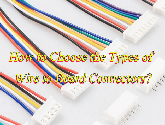
How to choose wire to board connectors types? Let’s discover wire to board connectors’ meaning, common types, selection guide, install and remove steps, difference between board to board connectors.
Are you troubled with these problems?
- Connector Lifespan Challenges?
- Small-batch Procurement Challenges?
- Mixed Gauge/Pitch Errors?
As a PCBA service supplier, EBest Circuit (Best Technology) can provide service:
- Long Lifespan: Phosphor bronze contacts + self-compensating structure, contact resistance <20mΩ after 100,000 plugging/unplugging cycles.
- Small-batch Rapid Response: 48-hour prototyping, 100-unit MOQ, quarterly price lock-in, inventory fluctuation buffer
- Universal Compatibility: 0.5-6.0mm full-range terminal library, free wire sequence conversion module.
Welcome to contact us if you have any inquiry for PCBA service: sales@bestpcbs.com.
What is Wire to Board Connectors?
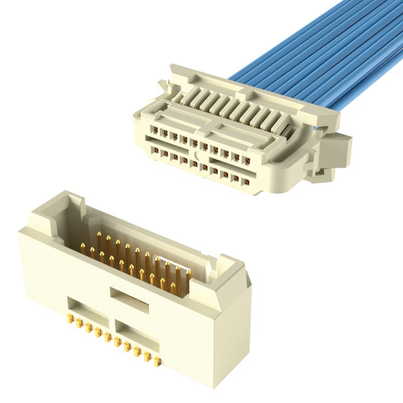
Wire to Board Connectors are components designed to connect wires to printed circuit boards (PCBs), enabling stable electrical signal and power transmission through precise insertion between plugs (female) and sockets (male). They feature key strengths: high reliability for sustained device operation, resistance to vibration, heat, water, and corrosion for harsh environments, quick plug-and-play capability for maintenance, and accurate signal/power delivery.
Structurally, metal pins are secured within an insulating housing, forming reliable contact with elastic metal contact slots; some models include color coding to prevent misinsertion. Structural variants include plug-in, locking, or soldering types, accommodating single-row, dual-row, or high-density pin configurations. These traits make them suitable for diverse applications across consumer electronics, automotive systems, industrial automation, medical equipment, and aerospace, providing versatile connection solutions for electronic devices.
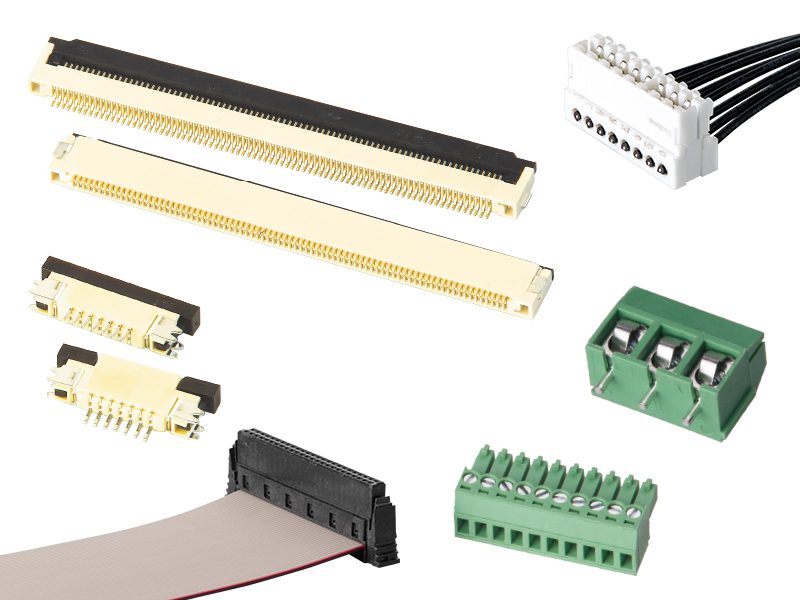
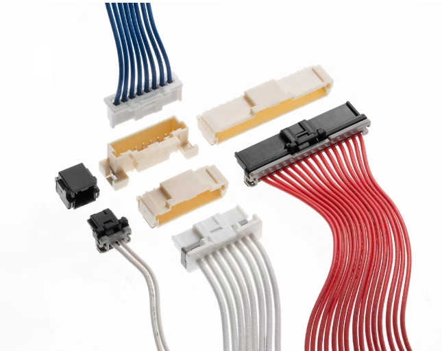
Common Wire to Board Connectors Types
Ultra-Narrow Pitch (0.4mm-0.8mm)
- Typical Series: Hirose DF40 (0.4mm), JST ZH (0.5mm), TE 0.635mm Micro-MaTch.
- Current Capacity: 0.3A-2A.
- Voltage Rating: 50V-250V.
- Applications: Ultra-thin laptop motherboards, drone flight controllers, micro camera modules, enabling high-density integration in compact electronic devices.
Narrow Pitch (1.0mm-1.25mm)
- Typical Series: JST SH/MOLEX 5051 (1.0mm), JST GH/MOLEX PicoBlade (1.25mm).
- Current Capacity: 1A-3A.
- Voltage Rating: 100V-250V.
- Applications: Smartphone camera modules, TWS earphone charging cases, action cameras, meeting space-efficient design needs in consumer electronics.
Standard Pitch (1.5mm-2.54mm)
- Typical Series: TE Micro-MaTch (1.5mm), JST XH/MOLEX 53047 (2.0mm), JST PH/MOLEX KK (2.54mm).
- Current Capacity: 2A-7A.
- Voltage Rating: 250V-500V.
- Applications: Smart home control boards, LED driver modules, appliance control boards (e.g., microwave ovens), balancing current capacity and spatial efficiency.
Wide Pitch (3.96mm-5.08mm)
- Typical Series: MOLEX 39700/JST EP (3.96mm), TE AMPMODU/JST VH (5.08mm).
- Current Capacity: 10A-20A.
- Voltage Rating: 600V-1000V.
- Applications: Industrial power supplies, photovoltaic inverters, power tool battery packs, supporting high-power transmission in rugged environments.
Special Pitch Extensions
- 0.3mm-0.635mm: Used for micro FPC/FFC connections (e.g., internal flexible circuits in smartphones).
- 6.2mm-21.2mm: Common in industrial power distribution and large equipment busbar connections, enabling ultra-high current transmission.
How to Choose the Types of Wire to Board Connectors?
1. Clarify Application Scenario Requirements
- High-density signal scenarios: 0.3mm-0.5mm pitch for compact devices like smartphones, achieving 8x higher retention force and superior vibration resistance.
- Industrial-grade high-temperature scenarios: 2.0mm-2.54mm pitch for automotive/industrial control units, operating from -40℃ to +105℃ with UL/C-UL certification.
- High-current power scenarios: 1.2mm-1.5mm pitch supporting 3A current with dual-beam contact design reducing resistance to ≤5mΩ.
2. Verify Electrical Parameter Matching
- Current carrying capacity: 1.2mm pitch rated for 0.5A-3A, 2.0mm pitch exceeding 5A. Match with circuit load (e.g., LT3942 DC-DC converter requires 1.2mm pitch for 2MHz operation).
- Voltage and signal integrity: Sub-0.8mm pitch requires optimized shielding for PCIe 4.0 applications to minimize crosstalk.
3. Evaluate Mechanical Structure Characteristics
Locking mechanism types:
- Positive locking: Enhances retention force by 8x for frequent insertion cycles.
- Side locking: Anti-mismatch design with 500-cycle mechanical life.
Contact materials: Copper alloy with nickel plating ensures ≤5mΩ contact resistance and corrosion resistance in humid environments.
4. Calculate Space Utilization Efficiency
- PCB area optimization: 1.2mm pitch reduces PCB area by 38% compared to 2.0mm, enabling 10% larger battery capacity in smartphones.
- Wiring density improvement: 0.5mm pitch supports 40 pins/cm² density, 4x higher than 2.54mm pitch for high-integration chip layouts.
5. Validate Industry Standard Compliance
- Safety certifications: UL 1977 for electrical clearance compliance, TÜV for automotive electronics.
- Environmental adaptability: IEC 60068-2-1 certified for -40℃ operation, IEC 60512 for ≤10% contact resistance change.
6. Consider Assembly Process Compatibility
- SMT surface mount: 1.2mm pitch compatible with automated 3D placement, boosting production efficiency by 50%.
- Through-hole soldering: 2.54mm pitch preferred for industrial equipment with high solder strength but 15-20% higher cost.
7. Balance Cost and Supply Chain
- Price comparison: 1.2mm pitch connectors average $0.30/unit, with stable inventory suppliers prioritized for bulk orders.
- Supply chain risk assessment: EBest Circuit (Best Technology) offers 3-5 day lead times to prevent project delays.
What is the Difference between Board to Board and Wire to Board Connectors?
Space and Layout Flexibility
- Wire to Board: Typically uses spacing ≥1.0mm, requires cable management. High flexibility suits scenarios needing cable insertion, such as power input/sensor connections in home appliance control boards or industrial power modules.
- Board to Board: Features ultra-small spacing (0.4mm-0.5mm) with vertical/horizontal stacking technology for direct PCB-to-PCB connection. Enables space savings and modular design, e.g., smartphone motherboard-camera module integration compressing thickness below 1mm.
Signal Transmission Performance
- Wire to Board: Signal attenuation/interference may occur due to cable length/material/termination process. Requires shielding (e.g., metal housing) and low-impedance wiring, better for mid-low speed signals (I²C/SPI) or high-current power distribution.
- Board to Board: Direct PCB connection with minimal signal path supports high-speed transmission (≥25Gbps). Differential pair design, shielding, and impedance matching (typical 100Ω) reduce attenuation/crosstalk, ideal for precision-demanding scenarios like 5G base stations and AI accelerators.
Reliability and Environmental Adaptability
- Wire to Board: Must handle mechanical stress (tension/bending) and environmental corrosion (moisture/acid mist). Enhanced reliability via IP67 protection, gold/nickel-gold plating, and elastic contact structures. Long-term use requires monitoring cable insulation aging/contact oxidation.
- Board to Board: Uses gold-plated terminals, elastic contacts, and locking structures (dual-hook latch) with stable contact resistance (≤20mΩ). Passes industrial tests (10,000+ insertion cycles, -40°C~125°C). Excellent vibration/temperature resistance suits automotive ECU/ADAS systems.
Cost and Manufacturing Considerations
- Wire to Board: Lower material costs but additional expenses for cables/termination/protection. MOQ/lead time critical in bulk procurement. Suitable for mid-low speed signal/power distribution in mass production.
- Board to Board: Higher initial costs from precision machining/special materials (LCP/beryllium copper). Supports automated SMT assembly with lower long-term maintenance costs. Ideal for high-integration, small-batch premium scenarios.
Design and Maintenance Convenience
- Wire to Board: Focus on termination processes/anti-mistake designs (color coding/polarization keys) for quick assembly. E.g., TWS earphone plug force (8-13N) balances usability; industrial scenarios optimize cable routing for maintainability.
- Board to Board: Supports flexible stack heights (0.5mm-20mm), angles (straight/bent), and packages (SMT/through-hole). Enables modular PCB layout planning, hot-swappable modules (e.g., smartwatch separation), and reduced repair costs.
How to Install Wire to Board Connectors?
Step 1: Tools and Materials Preparation
- Tools: Wire stripper, crimping tool/screwdriver, soldering iron, heat gun, torque wrench, multimeter, fixture holder.
- Materials: Wire-to-board connectors (BD24, LP series), wires (AWG22), heat shrink tubing, cold-pressed terminals, insulation displacement connectors (IDC).
- Safety: Wear anti-static wrist straps, ensure dry hands, and check wires for damage.
Step 2: Wire Preprocessing
- Stripping: Outer jacket 20mm±1mm, core wire 5-7mm (avoid conductor damage).
- Terminal Handling: Screw terminals tighten to ≤5.0N·m; soldering uses heat shrink tubing at 380°±40° for 3-6 seconds.
- Wire Fixation: Route wires through back cover to locking point; align ground/live/neutral wires with connector markings.
Step 3: Connector Assembly and Fixation
- Disassembly: Components include back cover, connector tail, module, and housing; wire routes to solder cup.
- Termination Methods: Screw (removable), soldering (vibration-resistant), IDC (efficient).
- Fixation: Secure housing with fixture, tighten back cover to 2.6±0.1N·m.
Step 4: PCB Installation and Anti-Mismating
- Positioning: Secure socket to panel/PCB with screws/clips; ensure precise alignment.
- Anti-Mismating: Use polarization keys, color coding, and alignment pins for correct insertion.
- Verification: Check alignment before insertion; “click” confirms secure locking.
Step 5: Performance Testing
- Electrical Tests: Contact resistance ≤milliohms, insulation ≥GΩ, dielectric strength ≥500VDC; multimeter checks for shorts/opens.
- Environmental Tests: Salt spray (96h), thermal shock (-40°C~125°C), vibration (USCAR-2).
- Physical Checks: Insertion force test, 3D model validation for clearance, supplier MOQ/lead time confirmation.
Step 6: Maintenance and Inspection
- Regular Checks: Inspect pins, solder joints, and fastenings; maintain ambient temperature within specs.
- Issue Resolution: Replace faulty connectors promptly; avoid unauthorized disassembly.
Step 7: Installation Precautions
- Torque Control: Adhere to manufacturer torque specs (e.g., 2.6±0.1N·m) to prevent damage/poor contact.
- ESD Protection: Wear anti-static wrist straps throughout to prevent electrostatic discharge.
- Wire Inspection: Post-processing, verify no exposed cores, damaged insulation, or conductive debris.
- Environmental Monitoring: Maintain ambient temperature within connector ratings (e.g., -40°C~125°C).
- Routine Maintenance: Quarterly checks for connector integrity, solder joint condition, and wire aging; replace worn parts immediately.
How to Remove Wire to Board Connectors?
Step 1: Power Disconnection and Safety Preparation
- Immediately disconnect device power (unplug or cut circuit supply) and wear an anti-static wrist strap or touch a grounded metal object to discharge static electricity.
- Prepare tools including fine-tip tweezers, plastic pry tools, small flathead screwdrivers, and a magnifying glass (optional). Ensure the operating environment is dry and dust-free.
Step 2: Connector Type Identification
- Observe external markings (e.g., JST/Molex brand logos), pitch size (0.5mm/1.0mm, etc.), locking mechanism (side latches/top press locks/screw fixation), and cable attachment methods (crimped/soldered/quick-release terminals). Refer to device manuals or PCB silkscreen for model confirmation to avoid misoperation.
Step 3: Unlocking the Locking Mechanism
- Latch-type connectors: For side latches, gently push the latch outward with tweezers while lightly pulling the connector tail. For top press locks, press the lock while lifting vertically to avoid tilting and deforming contacts.
- Screw-fixed connectors: Use a small flathead screwdriver to turn counterclockwise until the screw is fully loosened, then gently lift the connector.
- Latchless designs: Lift vertically with even force, avoiding lateral movement.
Step 4: Vertical Separation from PCB
- Dual-hand operation: Secure the PCB with one hand and grip the connector tail with the other, lifting vertically with steady, even force.
- For micro-connectors (e.g., 0.5mm pitch): Use a plastic pry tool to gently lift one side, progressively separating without scratching the PCB or contacts with metal tools.
- High-vibration applications: For industrial connectors, slightly shake laterally while lifting vertically to loosen gradually, preventing cable breakage from excessive force.
Step 5: Cable and Residue Handling
- Cable separation: If crimped or soldered, use professional crimping tools or a soldering station to detach cables without yanking, preventing wire breakage.
- PCB cleaning: Inspect sockets for debris or oxidation, clean with a soft brush or compressed air to ensure good contact for future installations.
- Connector inspection: Check for damage (bent contacts/cracked housing). For reuse, clean contacts with lint-free cloth dipped in alcohol and verify locking mechanisms function properly.
Step 6: Functional Verification and Testing
- After reconnecting power, use a multimeter or test equipment to verify circuit functionality, checking for shorts, opens, or signal anomalies to confirm removal didn’t disrupt normal operation.
Step 7: Documentation and Archiving
- Record key steps, tool usage, connector condition, and test results in detail. Photograph or video the process for future maintenance, troubleshooting, or reuse reference.
Why Choose EBest Circuit (Best Technology) as Wire to Board Connectors Supplier?
Reasons why choose us as wire to board connectors supplier:
- Fast Supply Response: Guarantee order confirmation within 24 hours, standard products ship in 3-5 business days. Urgent orders activate Green Channel for 48-hour expedited delivery to meet tight production deadlines.
- One-Stop Full-Process Service: Cover connector selection, PCB layout design, wire harness customization, SMT assembly, and functional testing in-house. Eliminate multi-vendor coordination, saving communication costs and time.
- Transparent Pricing System: Adopt base price + optional services model. Clearly list all costs (materials, processing, testing) on quotes. No hidden fees, ensuring precise budget control.
- Flexible Production for Timely Delivery: Smart scheduling systems support small batches (MOQ 100pcs) with quick turnaround and phased delivery for large orders. On-time delivery rate exceeds 98%.
- Strict Quality Control Standards: Products meet AEC-Q200 automotive-grade and ISO 9001/14001 certifications. Four full inspections + two random checks per key process. Core parameters (contact resistance, insulation impedance) 100% compliant, defect rate ≤50ppm.
- Stable Electronics Supply Chain: Strategic agreements with core material suppliers (LCP insulators, beryllium copper contacts, gold plating) ensure stable inventory and pricing, minimizing supply chain risks.
- Rapid Prototyping Service: Free samples and 3-day prototyping enable quick design validation, accelerating R&D cycles and time-to-market.
- Full-Lifecycle Technical Support: Dedicated FAE team provides 7×12 online assistance for selection, installation, and troubleshooting, ensuring smooth progression from design to mass production.
Welcome to contact us if you have any request for wire to board connector: sales@bestpcbs.com.