

Looking for high-performance LED PCB plate solutions? This guide explores aluminum base plate designs, thermal optimization, and manufacturer selection for superior LED performance.
EBest Circuit (Best Technology) excels as a leading aluminum base plate LED PCB manufacturer, combining 18 years of R&D expertise with precision engineering for unmatched thermal performance. Our aerospace-grade aluminum substrates (1.5-5.0mm thickness) achieve 240W/m·K thermal conductivity, reducing operating temperatures by 35% versus conventional boards through optimized copper-clad layouts and laser-drilled thermal vias. Equipped with IoT-enabled SMT lines and MIL-STD-883G compliance, we deliver 99.99% soldering accuracy for high-power LED arrays. Custom solutions include anti-corrosion anodized finishes, 92%-reflectivity ceramic coatings, and automotive-grade 12V/48V circuit designs tested under 150°C thermal shock cycles. Rapid 48-hour prototyping and ISO 14001-certified production ensure on-time delivery for horticulture systems, stadium lighting, and marine applications. Partner with us for optimized thermal solution starts here: sales@bestpcbs.com.
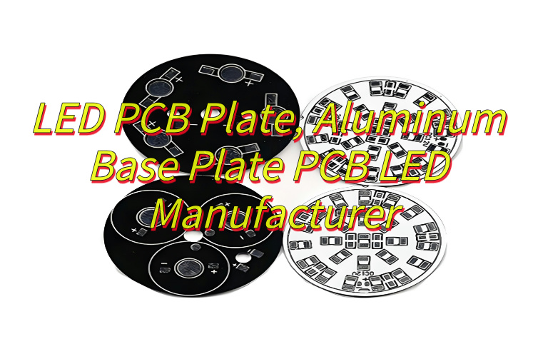
What Is LED PCB Plate?
A LED PCB plate refers to a specialized printed circuit board engineered to support and electrically interconnect light-emitting diodes (LEDs) while efficiently managing heat generated during operation. Constructed with a layered architecture, it typically integrates a conductive copper layer for electrical routing, a thermally conductive dielectric layer (often epoxy-based with ceramic fillers), and a metal substrate such as aluminum or copper alloy to enhance heat dissipation. Designed for applications ranging from automotive lighting to commercial displays, LED PCB Plate prioritize thermal stability through material selection (e.g., coefficient of thermal expansion matching) and structural features like embedded thermal vias or heat-spreading patterns. These boards undergo precision manufacturing processes, including controlled solder mask application and surface treatments like anodization, to ensure long-term reliability under thermal cycling and environmental stress. Their design balances electrical performance, mechanical durability, and thermal efficiency, making them essential components in high-power LED systems requiring consistent luminous output and extended operational lifespans.
What Is Structure of LED PCB Plate?
Structure of LED PCB plate:
- Conductive Copper Layer: A patterned copper foil (typically 1–3 oz thickness) forms electrical pathways for current distribution to LEDs, designed with precision-etched traces to minimize voltage drop and electromagnetic interference.
- Dielectric Insulating Layer: Composed of thermally enhanced epoxy resin infused with ceramic particles this layer electrically isolates the copper circuitry while providing thermal conductivity ≥3 W/m·K to transfer heat toward the metal substrate.
- Metal Core Substrate: Aluminum (6061-T6 alloy) or copper-based plates (1–5 mm thick) act as primary heat sinks, engineered with optimized surface flatness (Ra ≤1.6 μm) to ensure uniform thermal interface contact with external cooling systems.
- Thermal Management Features: Arrays of micro-vias (0.2–0.5 mm diameter) filled with conductive paste bridge copper layers to the substrate, reducing thermal resistance by up to 30%. Heat-spreading copper polygons are embedded beneath high-power LED footprints.
- Component Mounting Zones: Silver-plated or ENIG (Electroless Nickel Immersion Gold) pads provide oxidation-resistant surfaces for LED soldering, with solder mask openings precisely aligned to prevent solder bridging.
- Mechanical Stiffener: Edge-mounted aluminum frames or steel stiffeners (0.5–2.0 mm thickness) counteract warpage during thermal cycling, maintaining dimensional stability across operating temperatures (-40°C to +150°C).
- Protective Coatings: Conformal coatings (silicone or polyurethane-based) shield circuitry from moisture and contaminants, while anodized surfaces on aluminum substrates enhance corrosion resistance in harsh environments.
- Interlayer Bonding: High-pressure lamination processes fuse layers using thermally conductive adhesives (TG ≥150°C), ensuring delamination resistance under repeated thermal stress.

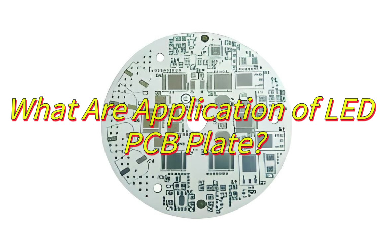
What Are Application of LED PCB Plate?
Applications of LED PCB plate:
Consumer and Commercial Lighting
- Role: LED PCB plates are widely used in everyday lighting fixtures, including bulbs, spotlights, and solar-powered lamps, due to their energy efficiency and compact design.
- Advantage: LED PCB plate dissipate heat effectively, ensuring long lifespans even in high-usage scenarios like floodlights and streetlights.
Automotive Lighting Systems
- Role: Critical for vehicle headlights, brake lights, and interior illumination, LED PCB plates enable high brightness and rapid response times.
- Advantage: LED PCB plate’s thermal management capabilities prevent overheating in demanding environments, enhancing safety and durability.
Telecommunications Equipment
- Role: LED indicators and displays in routers, servers, and networking devices rely on PCB plates for reliable signal transmission and heat dissipation.
- Advantage: Aluminum-core variants withstand prolonged operation without performance degradation, ensuring stable connectivity.
Medical Imaging and Diagnostic Tools
- Role: High-power LEDs in surgical lamps and endoscopes use PCB plates to maintain consistent illumination during procedures.
- Advantage: Superior thermal conductivity minimizes light flicker and ensures precise imaging, crucial for diagnostic accuracy.
Aerospace and Aviation Lighting
- Role: LED PCB plates power landing lights, cockpit displays, and cabin illumination in aircraft, prioritizing lightweight and rugged designs.
- Advantage: LED PCB plate’s resistance to vibration and extreme temperatures makes them ideal for aerospace applications.
Industrial and Machinery Displays
- Role: Heavy-duty equipment, such as CNC machines and factory automation systems, use LED PCB plates for control panels and status indicators.
- Advantage: High-temperature tolerance and mechanical stability ensure reliability in harsh industrial environments.
Entertainment and Stage Lighting
- Role: Dynamic LED fixtures in theaters, concerts, and studios utilize PCB plates to support rapid color changes and dimming effects.
- Advantage: Flexible PCB variants allow creative lighting designs while maintaining thermal efficiency during prolonged shows.
Horticultural and Aquarium Lighting
- Role: Specialized LED growth lights for plants and coral reefs incorporate PCB plates to optimize light spectrum and heat distribution.
- Advantage: Customizable aluminum plates enable precise wavelength control, fostering healthy growth in controlled environments.
How to Optimize Thermal Management of 12V LED PCB Aluminum Plate?
How to optimize thermal management of 12V LED PCB aluminum plate:
Use High-Thermal-Conductivity Insulation Layers
- Select dielectric materials with thermal conductivity exceeding 2.0 W/m·K (e.g., ceramic-filled polymers) to accelerate heat transfer from LEDs to the aluminum substrate.
- Avoid low-cost FR4 alternatives, as they trap heat and reduce 12V system efficiency.
Increase Copper Trace Thickness
- Choose 2 oz (70 µm) or thicker copper layers to minimize electrical resistance and heat generation in 12V circuits.
- Thicker copper reduces voltage drop across long traces, ensuring consistent LED brightness.
Incorporate Thermal Vias Under LED Pads
- Add plated through-holes (vias) directly beneath LED solder pads to channel heat vertically into the aluminum base.
- For 12V applications, space vias every 5–8 mm to balance thermal performance and manufacturing costs.
Apply Thermal Interface Materials (TIMs)
- Use silicone-based thermal pads or graphite sheets between the LED PCB and external heat sinks to eliminate air gaps.
- For 12V systems, ensure TIMs have low thermal impedance (<0.5°C·in²/W) to maintain efficiency under continuous operation.
Optimize Circuit Layout for Airflow
- Arrange high-power LEDs in a staggered pattern to avoid heat concentration and promote natural convection in 12V fixtures.
- Leave 3–5 mm gaps between components to allow air circulation, critical for enclosed designs like aquarium lights.
Attach Extended Heat Sinks
- Integrate aluminum or copper heat sinks with fins (≥20 mm height) to the edges of the 12V LED PCB aluminum plate.
- Anodize heat sinks black to enhance radiative cooling in low-airflow environments.
Leverage Active Cooling for High-Power 12V Applications
- For 12V floodlights or industrial modules, add miniature fans (e.g., 40x40mm brushless models) to force airflow over the PCB.
- Position fans to create a cross-flow pattern, targeting the hottest areas near LED drivers.
Optimize PCB Surface Finish
- Choose ENIG (Electroless Nickel Immersion Gold) or immersion silver finishes instead of HASL to improve solderability and thermal cycling resistance.
- Smooth finishes reduce surface roughness, minimizing localized hotspots in 12V systems.
Simulate Thermal Performance Pre-Production
- Use thermal simulation software to model heat dissipation under 12V operating conditions.
- Adjust component placement and copper weights based on simulated junction temperature data.
Consider Environmental Factors
- For outdoor 12V LED applications (e.g., solar streetlights), include conformal coatings to prevent moisture-induced thermal resistance.
- Elevate PCBs above mounting surfaces to avoid heat pooling in humid environments.
How to Choose An Aluminum Base Plate LED PCB Manufacturer?
Below are methods about how to choose an aluminum base plate LED PCB manufacturer:
Evaluate Technical Expertise
- Confirm the manufacturer’s experience with aluminum base plate LED PCB designs, including thermal via drilling, copper weight optimization, and dielectric layer selection.
- Inquire about their capability to handle high-power applications (e.g., 12V+ systems) and specialized finishes like ENIG or immersion tin.
Verify Quality Certifications
- Prioritize manufacturers with ISO 9001, ISO 14001, or UL certifications, ensuring adherence to industry standards for PCB fabrication.
- For automotive or medical LED applications, check for IATF 16949 or AS9100 compliance.
Assess Material Sourcing
- Ensure the supplier uses high-grade aluminum substrates (e.g., 6061 alloy) with consistent thickness and flatness.
- Ask about dielectric material options, such as prepreg with >2.0 W/m·K thermal conductivity for efficient heat dissipation.
Review Customization Capabilities
- Confirm support for flexible designs, including irregular shapes, cutouts, or multi-layer aluminum base plate LED PCB configurations.
- Check minimum order quantities (MOQs) and lead times for prototypes versus mass production.
Inspect Production Facilities
- Choose manufacturers with automated production lines to minimize human error and ensure consistency.
- Look for cleanroom environments for sensitive applications like SMD LED assembly or optical component integration.
Request Thermal Management Samples
- Ask for test reports demonstrating the aluminum base plate LED PCB’s thermal resistance (e.g., θJA values) under simulated loads.
- Evaluate solder mask adhesion and resistance to delamination after thermal cycling (-40°C to 125°C).
Check for Compliance and Safety Standards
- Ensure the manufacturer adheres to RoHS, REACH, and conflict-free mineral sourcing policies.
- For outdoor LED applications, confirm IP67/IP68 rating compliance for moisture resistance.
Analyze Post-Production Support
- Inquire about failure analysis services, including cross-sectioning or SEM imaging for defective boards.
- Confirm availability of technical support in multiple languages for global projects.
Compare Pricing and Terms
- Request quotes for identical specifications from multiple vendors to identify cost discrepancies.
- Beware of hidden fees for tooling, testing, or certification documentation.
Seek Customer References
- Contact previous clients to verify on-time delivery rates, defect rates (<1%), and responsiveness to rework requests.
- Prioritize manufacturers with case studies involving aluminum base plate LED PCB applications similar to yours (e.g., floodlights, automotive DRLs).

How to Ensure Uniform Light Output in Aluminum Base Plate LED PCB Production?
How to ensure uniform light output in aluminum base plate LED PCB production:
Optimize PCB Layout for Current Distribution
- Design traces with equal length and impedance to minimize voltage drops across LEDs. Use a “daisy-chain” or “balanced parallel” configuration to ensure consistent current flow.
- For large aluminum base plate LED PCB arrays, incorporate jumper wires or busbars to reduce resistance variations between zones.
Standardize LED Binning and Placement
- Source LEDs from the same bin (e.g., color temperature, luminous flux) to minimize intrinsic performance differences.
- Use pick-and-place machines with ±0.05 mm accuracy to align LEDs uniformly, avoiding angular deviations that cause light scattering.
Implement Reflective Coatings on Aluminum Substrates
- Apply a high-reflectivity white solder mask or silver ink coating to the aluminum base plate LED PCB surface to enhance light diffusion.
- Avoid matte finishes that absorb light; opt for glossy textures to maximize output efficiency.
Control Thermal Expansion During Assembly
- Preheat the aluminum base plate to 120–150°C before SMT reflow to reduce warpage and ensure even solder joint formation.
- Use nitrogen-atmosphere reflow ovens to minimize oxidation and voiding, which can cause localized hotspots and light inconsistency.
Incorporate Light-Mixing Features
- Add light-guide plates (LGPs) or diffusers above the aluminum base plate LED PCB to blend discrete LED emissions into uniform illumination.
- For edge-lit designs, etch microstructures (e.g., V-cuts) on the LGP to scatter light evenly.
Calibrate Drivers for Current Precision
- Use constant-current LED drivers with ±3% tolerance to eliminate flicker and brightness variations.
- For multi-channel aluminum base plate LED PCB systems (e.g., RGBW), implement individual channel calibration to balance color mixing.
Perform Post-Production Optical Testing
- Measure luminance and chromaticity uniformity using a 2D goniophotometer or integrating sphere.
- Flag boards with >5% deviation between LED zones for rework, such as adjusting resistor values or replacing outlier LEDs.
Enhance Thermal Management Consistency
- Machine-mill the aluminum substrate to a ±0.02 mm flatness tolerance to ensure uniform contact with thermal interface materials (TIMs).
- Avoid hand-applied TIMs; use automated stencils to apply consistent pressure-sensitive adhesive (PSA) layers.
Validate Design with Thermal and Optical Simulations
- Use software like Dialux to model heat dissipation and light distribution pre-production.
- Adjust LED spacing or power ratings based on simulated junction temperature maps to preempt hotspots.
Adopt Stringent Quality Control (QC) Protocols
- Implement automated optical inspection (AOI) to detect solder bridges, missing components, or misaligned LEDs.
- Conduct accelerated life tests (e.g., 1,000-hour TM-21) to identify early lumen depreciation in non-uniform batches.
How to Verify the Reliability of Aluminum Base Plate LED PCB After Production?
How to Verify the Reliability of Aluminum Base Plate LED PCB After Production
Conduct Environmental Stress Testing
- Temperature Cycling: Subject the aluminum base plate LED PCB to -40°C to 125°C cycles (1,000+ times) to simulate extreme thermal shocks. Monitor for solder joint cracks or dielectric layer delamination.
- Humidity Resistance: Use 85°C/85% RH (relative humidity) chambers for 96 hours to detect corrosion or insulation breakdown.
Perform Electrical Safety Checks
- Insulation Resistance Test: Apply 500V DC between copper traces and the aluminum base to ensure >100 MΩ resistance, preventing leakage currents.
- High-Potential (Hi-Pot) Testing: Verify dielectric strength by applying 1,500V AC for 1 minute without arcing or breakdown.
Inspect for Mechanical Integrity
- Peel Strength Testing: Measure the adhesion between copper layers and the substrate using a 90° peel test (minimum 1.5 N/mm for automotive-grade boards).
- Vibration Testing: Expose the PCB to 2–200 Hz sinusoidal vibrations (20G amplitude) to identify loose components or trace fractures.
Evaluate Thermal Performance
- Thermal Imaging: Use an infrared camera to map hotspots during 12V continuous operation. Flag boards with >10°C temperature differentials across the LED array.
- Thermal Cycling with Power: Operate the PCB at max rated current (e.g., 350mA for high-power LEDs) during temperature cycles to accelerate wear.
Assess Optical Stability
- Lumen Maintenance Testing: Measure initial luminous flux, then retest after 100–1,000 hours of aging. Reject batches with >5% depreciation.
- Color Shift Analysis: Use a spectrometer to check for Δuv deviations >0.005, indicating binning inconsistencies.
Execute Accelerated Life Tests
- TM-21 Compliance: Project LED lifespan (L70/L90) by operating PCBs at elevated temperatures (e.g., 85°C) and extrapolating data using Arrhenius equations.
- Switching Cycles: For smart lighting applications, test LED on/off durability (e.g., 100,000+ cycles) to verify solder joint reliability.
Perform Microscopic Analysis
- Cross-Sectioning: Cut and polish PCB samples to inspect via integrity, copper plating thickness, and dielectric voids.
- SEM Imaging: Scan for micro-cracks in solder joints or interfacial separation between layers.
Validate Compliance with Industry Standards
- IPC-6012 Compliance: Confirm the aluminum base plate LED PCB meets IPC’s Class 2 (dedicated service) or Class 3 (high-reliability) specifications.
- LM-80 Certification: For LED arrays, ensure photometric and thermal data align with LM-80 requirements for lumen maintenance reporting.
Audit Manufacturing Documentation
- Review SPC (Statistical Process Control) charts for critical parameters (e.g., solder paste volume, reflow oven temperature).
- Validate traceability records linking raw material lots to finished PCBs.
Implement Field Failure Simulation
- Use HALT (Highly Accelerated Life Test) chambers to combine thermal, vibration, and power stresses, uncovering weaknesses in <100 hours.
- For aquarium or marine lights, add salt-spray testing (5% NaCl, 24 hours) to assess corrosion resistance.
How Do Channel Aluminum Plate AI PCBs Optimize Aquarium Coral Lighting Systems?
How Do Channel Aluminum Plate AI PCBs Optimize Aquarium Coral Lighting Systems?
Precision Spectral Control for Coral Health
- Channel aluminum plate AI PCBs integrate multi-channel LED drivers to independently adjust wavelengths (e.g., 450nm blue, 420nm violet, and 660nm red) critical for coral symbiont photosynthesis.
- AI algorithms dynamically balance light intensity and spectrum based on coral species (e.g., SPS, LPS) and growth stages, mimicking natural tidal cycles.
Advanced Thermal Management for Spectral Stability
- The aluminum substrate’s channel design maximizes surface area for heat dissipation, preventing thermal drift that shifts LED wavelengths (e.g., >5nm shift at 85°C).
- Embedded thermal sensors trigger cooling fans or dim LEDs if junction temperatures exceed safe limits, ensuring consistent color rendering.
AI-Driven Light Scheduling and Adaptation
- Machine learning models analyze water parameters (temperature, salinity, pH) and coral fluorescence data to optimize daily light cycles.
- For example, AI might reduce UV exposure during algae blooms or boost actinic blue during coral spawning periods.
Uniform Light Distribution via Micro-Channel Diffusers
- The aluminum plate’s etched channels double as light guides, blending discrete LED emissions into homogeneous illumination.
- This eliminates hotspots that stress corals and reduces the need for supplementary diffusers, lowering system cost.
Real-Time Anomaly Detection
- AI PCBs monitor current draw, voltage fluctuations, and LED decay rates to predict failures (e.g., 10% lumen depreciation triggers preemptive replacement alerts).
- For aquarium systems, this minimizes downtime and prevents sudden light crashes that harm sensitive coral.
Energy Efficiency Through Load Optimization
- Channel aluminum PCBs with AI power management reduce energy use by 30% compared to fixed-output LED drivers.
- By syncing light output to actual coral needs (e.g., dimming during night hours), operators save on electricity and cooling costs.
Corrosion Resistance for Marine Environments
- The aluminum substrate is anodized or coated with Parylene C to resist saltwater corrosion, extending PCB lifespan in humid aquarium hoods.
- Channel designs prevent water pooling, a common failure point in flat aluminum PCBs.
Integration with IoT Ecosystems
- AI PCBs connect to aquarium controllers via Wi-Fi/Bluetooth, enabling remote spectrum tuning and alerts through smartphone apps.
- For advanced setups, they interface with dosing pumps and wave makers to create holistic coral care systems.
Reduced Maintenance via Self-Cleaning Features
- Some channel aluminum PCBs incorporate hydrophobic coatings to repel salt spray and biofilm, maintaining light transmission without manual wiping.
- AI-triggered periodic high-intensity pulses (e.g., 150% power for 5 minutes) burn off mineral deposits.
Scalability for Diverse Aquarium Sizes
- Modular channel aluminum PCBs with plug-and-play AI modules allow hobbyists to expand lighting systems as coral colonies grow.
- For commercial aquariums, master-slave configurations enable synchronized control across hundreds of LED fixtures.