

The world is buzzing with 5G. Mobile networks are rolling it out at full speed, and every new smartphone comes with 5G capability. But when you look at your screen and see “5G UW” or “5G UC,” confusion kicks in. What do these terms mean? Are they faster than LTE, or just marketing?
In the debate of 5G UW vs 5G UC, it’s important to break down the meaning of these labels, what kind of performance you can expect, and why they matter for industries far beyond mobile phones. At the heart of this revolution sits high speed PCB technology, the invisible backbone that makes next-generation communication possible.
What is 5G?
5G is the abbreviation of 5th Generation Mobile Communication Technology. It is standardized by the International Telecommunication Union (ITU) and achieves performance breakthroughs through technologies such as millimeter waves, massive antenna arrays (Massive MIMO), and beamforming. Its network architecture supports both standalone networking (SA) and non-standalone networking (NSA), providing infrastructure for the Internet of Things and industrial internet, among others.
Key features of 5G network:
- High rate: The theoretical peak transmission speed reaches 20 Gbps, which is over 10 times that of 4G and can support large data applications such as 8K videos, VR/AR.
- Low latency: The air interface latency is as low as 1 ms, meeting the real-time interaction requirements of autonomous driving, remote surgery, etc.
- Large connection: Each square kilometer can connect millions of devices, promoting the implementation of IoT scenarios such as smart cities and smart homes.

Types of 5G Network
To understand why your phone sometimes shows “UW” or “UC,” you need to know the different flavors of 5G. The 5G network can be divided into three types according to its band:
1. Low-band 5G: Operates close to traditional LTE frequencies. It can cover long distances and penetrate buildings well, but the speed jump is modest. Think of it as a slightly upgraded LTE.
2. Mid-band 5G: Provides a sweet spot. It offers significantly higher speeds while still covering large areas. This band is the workhorse of most 5G deployments.
3. High-band 5G (mmWave): This is the superstar of speed. It delivers multi-gigabit per second downloads and ultra-low latency. However, signals don’t travel far and can be blocked by walls, trees, or even your own hand.
Different carriers use different strategies. Verizon highlights its Ultra Wideband service. T-Mobile emphasizes Ultra Capacity. AT&T uses “5G+.” While the names differ, the underlying technology rests on these three bands.
What is 5G UW?
So, what does UW mean next to 5G? On Verizon’s network, UW stands for Ultra Wideband. It is the branding the company uses for its fastest 5G connections.
In practice, 5G UW usually refers to two types of spectrum:
- mmWave spectrum: Ultra-high frequencies that deliver multi-gigabit speeds. Ideal for stadiums, airports, or city centers where many users need blazing speed.
- C-band spectrum (mid-band): Offers a balance of speed and range. Verizon began applying the UW label to this spectrum too, giving customers a wider area of high-performance 5G.
When you see UW, your phone is using Verizon’s premium 5G service. This can mean downloading movies in seconds, enjoying lag-free cloud gaming, or using advanced business apps while on the go.

What is 5G UC?
On T-Mobile devices, you may see “5G UC.” This stands for Ultra Capacity, T-Mobile’s label for its fastest 5G network.
UC typically combines mid-band spectrum (like 2.5 GHz frequencies it acquired from Sprint) with mmWave spectrum in select locations. The result is a service that covers a larger portion of the country than Verizon’s UW while still offering high speeds.
In a practical sense, when comparing 5G UW vs 5G UC, both represent faster-than-standard 5G. UW often peaks at higher speeds in dense urban areas, while UC provides broader high-speed coverage across suburbs and rural zones.
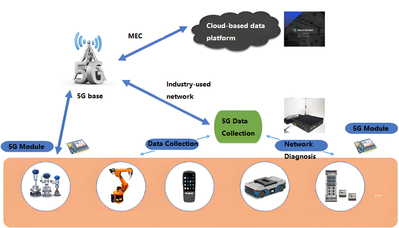
The Impact of 5G on Various Industries
- Healthcare: Surgeons can perform operations remotely with robotic assistance. Telemedicine becomes smooth with real-time video. Wearable devices track patient data continuously.
- Automotive: Autonomous vehicles rely on instant communication with sensors, traffic systems, and other cars. Millisecond latency makes this possible.
- Manufacturing: Smart factories use connected machines and predictive maintenance powered by IoT. Downtime is reduced, efficiency skyrockets.
- Entertainment: Virtual reality and augmented reality experiences become practical. Gamers stream console-quality titles from the cloud without lag.
- Logistics and Retail: Supply chains operate with real-time tracking. Retailers use AR shopping and automated checkout.
All these applications depend on one thing: hardware that can handle high-frequency, high-speed signals. And that is where high speed PCBs enter the picture.
Why is 5G UW So Slow Sometimes?
If UW is supposed to be ultra-fast, why do some users report slower speeds? There are several reasons.
1. Coverage limitations: mmWave signals travel only short distances. If you step outside the coverage zone, your phone falls back to slower bands.
2. Obstructions: Buildings, glass, or even a crowd can block mmWave signals.
3. Congestion: In busy areas, too many users may strain the network.
4. Device limitations: Not all phones handle every 5G frequency equally well.
Even with these challenges, 5G UW is still faster than LTE under proper conditions. The performance gap will continue to widen as carriers expand coverage and upgrade infrastructure.
Is 5G UW Better than LTE?
Yes—when conditions are right, 5G UW easily outperforms LTE. It offers higher data speeds, lower latency, and more capacity for simultaneous users. While LTE still covers more remote areas, it cannot match the performance levels of UW or UC in urban and business zones.
Here’s a quick comparison:
| Feature | 5G UW (Ultra Wideband) | 5G UC (Ultra Capacity) | LTE (4G) |
| Typical Speed | 1–3 Gbps (can peak higher) | 400 Mbps – 1 Gbps | 10–50 Mbps |
| Latency | ~5–10 ms | ~10–20 ms | ~30–50 ms |
| Coverage | Limited (urban hot spots) | Wider (cities + suburbs) | Broad (urban + rural) |
| Best For | Cloud gaming, AR/VR, ultra-HD streaming | Everyday high-speed browsing, business apps | Standard streaming, web browsing |
| Signal Range | Short (mmWave limited) | Moderate (mid-band focus) | Long (low-band focus) |
| Battery Impact | Higher drain | Moderate | Lower drain |
In short:
- UW = maximum speed but short range.
- UC = balanced speed and coverage.
- LTE = wide coverage but slower speeds.
Can You Turn Off 5G UW on iPhone?
Yes, iPhones give you control over how you connect. In Settings → Cellular → Voice & Data, you can choose:
- 5G On: Always use 5G when available.
- 5G Auto: Switch between LTE and 5G to save battery.
- LTE: Stick to LTE only.
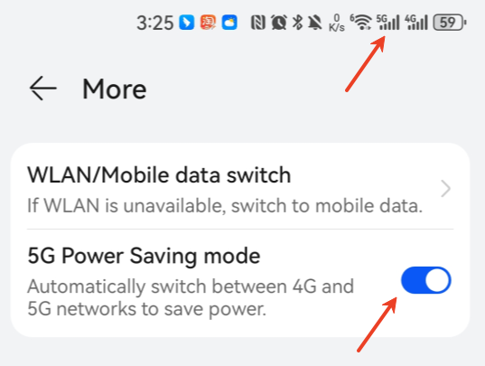
This means you can disable UW if you prefer longer battery life or find LTE more stable in your area. It gives you flexibility, so you are not locked into one option. Below picture show my phone ‘s 5G network is trun on.
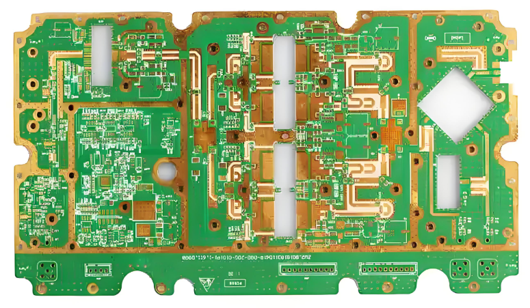
The Key Part in 5G Network: High Speed PCB
When people talk about 5G, they often focus on antennas, towers, and smartphones. But inside every device lies a silent hero: the high speed PCB.
High-Speed PCB refers to a printed circuit board designed for high-speed digital circuits (where the signal transmission rate usually exceeds 1 Gbps or the frequency reaches the GHz level). Its core lies in addressing issues such as reflection, crosstalk, and delay in high-speed signal transmission. To ensure signal integrity, it requires the application of key technologies such as impedance control and differential signal design. Without it, 5G’s high data rates would collapse into noise and interference.
Every 5G base station, router, or phone relies on these PCBs to deliver consistent performance. They are the backbone of the 5G era.
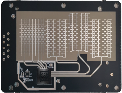
Features of High Speed PCB
- Low-loss materials: Special laminates that minimize signal degradation.
- Controlled impedance traces: Precise line widths and spacing for stable signal flow.
- Ground planes: Reduce noise and prevent interference.
- Differential pairs: Keep high-speed signals balanced and synchronized.
- Multilayer stack-ups: Allow complex routing without sacrificing performance.
High Speed PCB Design Consideration
A successful PCB layout begins with asking one important question: is this truly a high speed design? If yes, then every step of the design requires extra caution. Not all PCBs demand the same rigor, but once signal speeds reach certain thresholds, they must be treated as high speed circuits.
1. Determining if a Design is High Speed
To confirm whether a circuit qualifies as high speed, engineers evaluate three key parameters:
- Maximum signal frequency (Fm): The highest operating frequency in the circuit.
- Rise or fall time (Tr): The fastest transition time of digital signals.
- Data transfer rate (DTR): The maximum bit rate of data communication.
These parameters are related:
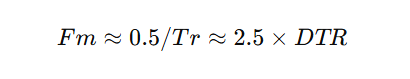
From this, the highest signal frequency can be derived.
Next, the wavelength (λm) of the signal on the PCB must be calculated:

where v is the signal speed on the PCB, approximately 11.8 in/ns in vacuum, but lower in PCB materials depending on the dielectric constant.
If the interconnect length l < λm / 12, then the trace can be treated as a regular connection. But if l ≥ λm / 12, it must be treated as a high speed interconnect. Another rule: if propagation delay along the trace exceeds half of the signal rise/fall time, the trace must be considered high speed.
In practice, when signal frequencies reach 45–50 MHz or higher, and such signals dominate the design, the board should be treated as a high speed PCB.
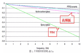
2. Material Impact on High Speed Design
PCB material strongly affects signal velocity and propagation delay. Different laminates have different dielectric constants (Er) and effective values (Ereff), which directly influence delay times.
For example:
- Isola 370HR: Delay ~145–170 ps/in
- Isola I-Speed: Delay ~139–162 ps/in
- Rogers 4000 series: Delay ~139–161 ps/in
- Tachyon 100G / Rogers 3003: Faster signal propagation at ~128–147 ps/in
Low-loss materials with stable dielectric properties are always preferred for GHz-range designs. Choosing the right laminate is a fundamental step in achieving reliable high speed performance.
3. Evaluating Design Complexity
Beyond speed, complexity also drives design considerations. Factors include:
- Component density: More parts per unit area increase routing difficulty.
- Fine-pitch BGAs: Devices with 0.5 mm or 0.4 mm pitch often require blind and buried vias for fan-out.
- Interface types: High-speed protocols like HDMI, DDR, and Gigabit Ethernet need strict impedance control.
- Impedance requirements: Controlled 50Ω single-ended or 100Ω differential traces may be mandatory.
- Mixed-signal design: Coexistence of digital, RF, and analog circuits complicates stack-up and layout.
- Strict layer stack-up: Some designs require 6, 8, or more layers with specific ground/power plane placement.
- Component pin density: More than 17 pins per cm² indicates a demanding layout.
- Part density: Over 1.55 components per cm² also raises complexity.
- Electrical restrictions: Sensitive circuits may impose strict EMI or crosstalk requirements.
The higher the density and the more protocols involved, the greater the need for specialized PCB techniques.
4. Key Design Guidelines for High Speed PCBs
When a design qualifies as high speed, the following must be considered:
- Treat interconnects as transmission lines. High speed traces are not simple point-to-point connections; they require impedance-controlled routing to reduce reflections, crosstalk, and EMI.
- Control signal attenuation. Use proper materials, trace widths, and terminations to keep losses within acceptable limits.
- Match PCB technology to complexity. Choose fabrication techniques that support component density, fine-pitch devices, and advanced protocols.
- Manage EMI carefully. Proper grounding, return paths, and shielding are vital to keep emissions under control.
- Maintain power integrity. Even under high-frequency noise, stable power delivery is crucial. Use decoupling capacitors, well-designed PDNs, and sufficient ground planes.
- Adopt specialized routing strategies. Differential pair routing, via optimization, and stack-up planning must be applied based on density and frequency needs.
In short, high speed PCB design demands a holistic view—balancing materials, geometry, signal integrity, EMI control, and manufacturability.
EBest Circuit (Best Technology) – Your Reliable High Speed PCB Manufacturer
At EBest Circuit (Best Technology), we understand the demands of the 5G era. We produce high speed PCBs that meet strict performance requirements for telecom, automotive, aerospace, and medical applications.
- Certifications: ISO9001, ISO13485, IATF16949, and AS9100D.
- Quality control: Rigorous inspections and advanced testing equipment.
- Traceability: MES system tracks every component and process.
- Support: Professional engineering team to assist with stack-up design, impedance control, and thermal solutions.
- Cost efficiency: Competitive pricing without sacrificing reliability.
If your projects require high frequency, high speed solutions, EBest Circuit (Best Technology) is here to deliver boards that perform under pressure.
FAQs
1. What does UW mean next to 5G?
It means Ultra Wideband, Verizon’s label for its premium 5G service.
2. Is 5G UW faster than 5G UC?
UW can reach higher peak speeds, but UC offers broader high-speed coverage.
3. Does 5G UW use more battery?
Yes, connecting to high-frequency bands can drain more power.
4. Is 5G better than LTE?
Yes, 5G offers faster speeds, lower latency, and better capacity compared with LTE.
5. Why do some areas still lack 5G UW coverage?
Because high-frequency networks are costly to deploy and signals don’t travel far. Expansion is ongoing.