

Seeking 3w LED PCB expertise? Dive into its applications, PWM optimization, manufacturer selection, testing, lifespan tactics, and 25W PCB contrasts in this guide.
EBest Circuit (Best Technology) excels in delivering LED PCB solutions from low power 3W to high performance 30W boards, ensuring versatility for diverse applications. With rapid production cycles, including 24-hour prototyping for urgent orders, we meet demanding timelines without compromising quality. Our PCBs integrate high-thermal-conductivity aluminum substrates (6061-T6, ≥2.0 W/m·K) and certified thermal resistance reports (≤5°C/W), ensuring efficient heat management. Rigorous 96-hour aging tests validate ≤2% luminous decay under prolonged high-power use, guaranteeing reliability. Custom designs are supported, paired with dedicated pre- and post-sales teams offering end-to-end guidance. For durable, high-efficiency LED PCBs backed by technical precision and responsive service, contact us to discuss your requirements.
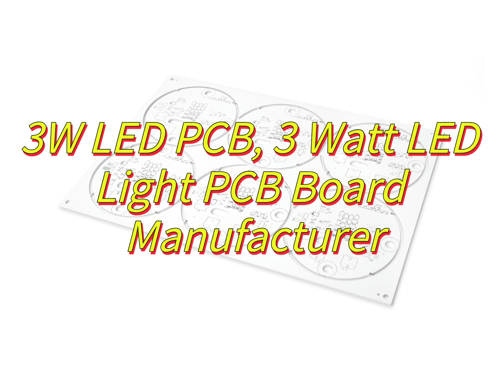
What Is 3W LED PCB?
A 3w LED PCB refers to a printed circuit board specifically engineered to support light-emitting diodes (LEDs) operating at a power rating of 3 watts. This type of PCB typically integrates aluminum or metal-core substrates to manage heat generated during high-brightness operation, ensuring stable thermal performance and prolonging LED lifespan. The design focuses on efficient current distribution, durable solder joints, and compact layouts optimized for lighting applications such as bulbs, downlights, or portable fixtures. Engineers prioritize material thickness (e.g., 1.6mm aluminum base) and dielectric layer conductivity to balance thermal dissipation with electrical insulation. These boards often comply with industry standards for energy efficiency and safety, making them suitable for residential and commercial lighting systems requiring reliable, low-profile solutions.
What Are Application of 3W LED PCB?
Below are the application of 3w LED PCB:
- Household Lighting Fixtures – Compact 3W LED PCB boards are widely used in ceiling bulbs, table lamps, and wall-mounted fixtures. Their efficient thermal management ensures stable brightness while minimizing energy consumption.
- Commercial Downlight Systems – Retail stores and offices deploy 3W LED PCBs in recessed downlights for uniform illumination. Aluminum substrates prevent overheating in prolonged daily operations.
- Portable Work Lights – Battery-powered tools and handheld devices integrate 3W LED PCBs due to their low-profile design and durability. Heat-resistant soldering ensures reliability in rugged environments.
- Automotive Interior Lighting – Dashboard lights and cabin accent lighting utilize 3W LED PCBs for vibration resistance and consistent color temperature. Metal-core designs withstand temperature fluctuations.
- Decorative Lighting Strips – Flexible 3W LED PCB variants enable custom-shaped LED strips for architectural accents or signage. Uniform current distribution avoids hot spots in extended runs.
- Emergency Exit Signs – Low-power 3W LED PCBs provide energy-efficient backlighting for safety signage. Optimized layouts ensure compliance with fire safety regulations.
- Medical Task Lamps – Surgical and diagnostic equipment use 3W LED PCBs for flicker-free illumination. Dielectric layers isolate circuits from conductive housings.
- Horticultural Grow Lights – Small-scale indoor farming systems employ 3W LED PCBs for targeted plant-growth spectra. Thermal stability prevents spectrum drift over continuous operation.

Why Choose 3W over 9W LED Bulb PCB for Outdoor Lighting?
Here are reasons why choose 3w over 9w LED bulb PCB for outdoor lighting:
Lower Energy Consumption Reduces Operational Costs
- A 3W LED PCB consumes one-third the power of a 9W equivalent, significantly lowering electricity bills for outdoor systems operating 10–12 hours daily. This efficiency aligns with solar-powered or battery-dependent setups, where energy conservation directly impacts runtime and maintenance frequency.
Lower Initial Hardware and Production Expenses
- Components for 3W PCBs, such as thinner aluminum substrates (1.0–1.6mm) and smaller heat sinks, cost 15–20% less than those for 9W models. Bulk manufacturing further reduces unit prices, making 3W boards economical for large-scale outdoor projects.
Simplified Thermal Design Cuts Engineering Overheads
- Unlike 9W LED PCBs requiring copper-core layers or finned heat sinks, 3W variants achieve stable thermal performance with basic aluminum bases. This simplifies production and reduces material waste, lowering overall design costs.
Extended Durability Reduces Replacement Frequency
- Prolonged heat exposure in 9W PCBs accelerates LED degradation, often necessitating replacements every 18–24 months. In contrast, 3W boards maintain 70% lumen output beyond 25,000 hours due to milder thermal stress.
Compact Size Suits Space-Limited Installations
- 3W LED PCBs enable slim, lightweight fixtures ideal for portable outdoor gear like camping lamps or tent lighting. By contrast, bulkier 9W boards demand larger housings, increasing material and shipping expenses.
Compatibility with Low-Capacity Power Systems
- Solar panels or small batteries efficiently support 3W PCBs at 3.3–12V DC. Higher 9W loads often require voltage boosters or larger batteries, adding 25–30% to upfront system costs.
Lower Risk of Overheating in Enclosed Fixtures
- Sealed outdoor housings trap heat, pushing 9W PCB junction temperatures above 85°C and risking premature failure. 3W models stay below 60°C, ensuring reliable performance in weatherproof enclosures.
Cost-Effective Modular Configurations
- Combining multiple 3W PCBs allows scalable brightness adjustments, while a single 9W unit failure disrupts entire systems. Replacing a 9W PCB typically costs 3–4x more than individual 3W modules.
How to Optimize PWM Controls Circuits for 3W LED PCBs?
Set Switching Frequency Between 200 Hz and 1 kHz
- Balance flicker prevention and efficiency by avoiding frequencies below 200 Hz (visible flicker) or above 1 kHz (increased MOSFET switching losses). For outdoor fixtures, 500 Hz often works well, minimizing audible noise from inductors while maintaining stable dimming.
Use Low Rds(on) MOSFETs for Reduced Heat Generation
- Select MOSFETs with on-resistance below 50 mΩ to minimize voltage drops and heat buildup during PWM switching. Pair these with gate drivers like TC4420 to ensure fast turn-on/turn-off times, reducing power dissipation.
Implement Current Feedback for Stable Brightness
- Add a shunt resistor (0.1–0.5Ω) in series with the 3W LED PCB to monitor current. Feed this data to a microcontroller, adjusting PWM duty cycles to compensate for voltage fluctuations caused by temperature or battery drain.
Filter High-Frequency Noise with RC Snubbers
- Place a 10nF capacitor and 10Ω resistor in parallel across the LED PCB terminals. This absorbs voltage spikes generated by PWM switching, protecting LEDs and reducing electromagnetic interference (EMI) in nearby sensors.
Optimize Duty Cycle Resolution for Smooth Dimming
- Use 10–12 bit PWM resolution to enable fine brightness adjustments. For example, 10-bit control allows 1,024 dimming steps, preventing visible “steps” when transitioning between light levels in smart systems.
Route High-Current Traces Short and Wide
- Design PCB traces carrying PWM-switched current to be at least 2mm wide, minimizing resistance and inductance. Separate these traces from analog sensor lines to avoid coupling noise into feedback circuits.
Add Thermal Derating via Software
- Program the PWM controller to gradually reduce duty cycles when temperature sensors detect PCB heating above 60°C. This preserves LED lifespan without abrupt brightness changes noticeable to users.
Test Under Real-World Voltage Fluctuations
- Validate PWM stability with input voltages varying ±20% from nominal (e.g., 9–14V for 12V systems). Check for flicker or color shifts, adjusting feedback loop parameters like integral gain if needed.

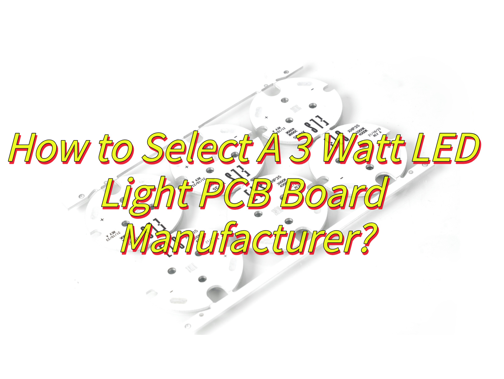
How to Select A 3 Watt LED Light PCB Board Manufacturer?
Here are methods about how to select a 3watt LED light PCB board manufacturer:
Thermal Performance and Material Quality
- Ensure the manufacturer uses high-thermal-conductivity aluminum substrates, such as 6061-T6 alloy, with a minimum thermal conductivity of 2.0 W/m·K. Request detailed thermal resistance (Rθ) test reports confirming values ≤ 5°C/W, which guarantee efficient heat dissipation from LED junctions to the heatsink. This is critical for maintaining LED lifespan and preventing overheating in high-power applications.
Aging and Reliability Testing
- Choose a supplier that conducts 96-hour accelerated life testing under extreme conditions (e.g., 85°C temperature and 85% humidity). Post-test data should show lumen maintenance ≥98% and minimal color shift (Δuv ≤0.005), ensuring long-term performance stability even in demanding environments like industrial or outdoor lighting.
Production Equipment and Quality Controls
- Look for manufacturers equipped with multi-zone reflow ovens for precise soldering profiles, Automated Optical Inspection (AOI) systems to detect defects, and X-ray machines for validating component integrity. Certifications like ISO 9001 or IATF 16949 indicate adherence to strict quality standards.
Customization and Design Support
- Choose a partner capable of accommodating specialized designs, such as thermal via arrays (≥50 vias/dm²) for enhanced heat transfer, hybrid circuits integrating 3W LEDs with other components, and corrosion-resistant surface finishes like ENIG.
Compliance with Safety Standards
- Verify certifications such as UL 8750 (LED safety), EN 62471 (photobiological safety), and RoHS/REACH compliance to ensure products meet regulatory requirements.
Rapid Prototyping and Quick Turnaround
- Select a manufacturer offering 24-hour prototype delivery using laser-cut stencils and automated assembly. Free Design for Manufacturing (DFM) reviews can optimize your layout for cost and efficiency, reducing time-to-market.
Supply Chain Reliability
- Confirm the manufacturer sources high-quality materials, such as LED packages from reputable suppliers and aluminum substrates with consistent specifications. A stable supply chain minimizes lead times and material shortages.
Warranty and Technical Support
- Negotiate agreements covering 5-year warranty with a failure rate ≤3% under continuous operation, free replacement for boards exceeding 2% lumen depreciation within 2 years, and technical support for troubleshooting and design iterations.
Communication and Collaboration
- Partner with manufacturers in compatible time zones for real-time collaboration. Ensure they offer multilingual support and use project management tools for transparency.
Customer Feedback
- Review case studies and contact existing clients to validate the manufacturer’s expertise in LED lighting applications and their responsiveness to customer needs.
How to Test and Validate 3W LED PCB Performance After Production?
Validating the performance of 3W LED PCBs after production ensures reliability, safety, and compliance with design specifications. Below is a structured approach to testing, covering critical parameters from electrical behavior to long-term durability:
1. Electrical Performance Testing
- Current-Voltage (IV) Characterization: Measure forward voltage (Vf) at rated current (e.g., 700mA) using a precision source meter. Ensure values align with the LED datasheet (typically 2.8–3.6V for 3W LEDs).
- Power Consumption Verification: Calculate power (P = V × I) to confirm it matches the 3W rating. Deviations >5% may indicate soldering defects or component mismatches.
- Thermal Shutdown Testing: Gradually increase ambient temperature while monitoring current. The PCB should automatically reduce power or shut down at 120–130°C to prevent damage.
2. Thermal Management Validation
- Infrared Thermography: Use a thermal camera to map temperature distribution across the PCB. Identify hotspots near LED junctions or drivers; temperatures should not exceed 100°C under full load.
- Thermal Resistance (Rθ) Measurement: Calculate Rθ using the formula Rθ = (Tj – Ta) / P, where Tj is junction temperature, Ta is ambient, and P is power. Aim for Rθ ≤5°C/W to ensure efficient heat dissipation.
3. Optical Performance Assessment
- Luminous Flux Measurement: Use an integrating sphere to quantify total light output (lumens). A 3W LED should emit 250–350 lumens, depending on efficacy (80–120 lm/W).
- Spectral Power Distribution (SPD): Analyze light quality using a spectrometer. Verify correlated color temperature (CCT) matches specifications (e.g., 2700K–6500K) and check for color uniformity across batches.
- Beam Angle Verification: Employ a goniophotometer to confirm beam patterns (e.g., 120° flood vs. 30° spot) meet design targets.
4. Mechanical and Environmental Stress Testing
- Vibration Resistance: Subject the PCB to random vibration profiles (e.g., 2–2000 Hz, 5G RMS) for 2 hours. Check for solder joint cracks or component displacement.
- Moisture Sensitivity Testing: Expose boards to 85°C/85% RH for 96 hours. Inspect for delamination, corrosion, or electrical failures post-exposure.
- Thermal Cycling: Cycle between -40°C and 125°C for 100 cycles. Ensure no failures in electrical continuity or LED performance.
5. Long-Term Reliability Trials
- Accelerated Life Testing: Operate LEDs at 85°C and 85% RH for 96 hours. Measure lumen maintenance and color shift; aim for ≥98% lumen retention and Δuv ≤0.005.
- Switching Endurance: Cycle the LED ON/OFF at 1-second intervals for 100,000 cycles. Monitor for flicker or catastrophic failures.
6. Safety and Compliance Checks
- Dielectric Withstand Test: Apply 1500V AC between PCB traces and the aluminum base for 60 seconds. Ensure no breakdown occurs.
- Flammability Rating: Confirm the PCB substrate meets UL94 V-0 standards to resist fire propagation.
7. Final Quality Audits
- Automated Optical Inspection (AOI): Scan for solder defects (e.g., bridges, voids) and component misalignment.
- Functional Testing: Verify all LEDs light up at specified brightness levels using a custom jig with current-controlled power supplies.
How to Expand the Lifespan of 3W LED PCBs in Smart Systems?
Extending the operational life of 3W LED PCBs in smart systems requires a multi-faceted approach, combining hardware optimization, software controls, and environmental safeguards. Below is a structured guide to enhance durability and reliability:
Thermal Management Optimization
- Enhance Heat Dissipation: Use high-thermal-conductivity aluminum substrates (e.g., 6061-T6 alloy with ≥2.0 W/m·K thermal conductivity) to reduce junction temperatures. Supplement with thermal vias (≥50 vias/dm²) to improve heat transfer to heatsinks.
- Active Cooling Integration: Incorporate small fans or heat pipes in high-power applications to maintain PCB temperatures below 80°C during prolonged use.
Intelligent Power Regulation
- Dynamic Current Adjustment: Implement PWM dimming algorithms that reduce LED current during low-demand periods. For example, lower brightness to 30% during daylight hours in smart streetlights.
- Temperature-Compensated Drivers: Use LED drivers with built-in thermal feedback loops to automatically reduce current when PCB temperatures exceed 90°C, preventing overheating.
Environmental Protection Measures
- Conformal Coating: Apply silicone or polyurethane coatings to protect PCB traces from moisture, dust, and chemical corrosion. This is critical for outdoor or industrial smart systems.
- UV Resistance: Use anti-UV solder masks and epoxy resins to prevent degradation of PCB materials under prolonged sunlight exposure.
Predictive Maintenance Integration
- Condition Monitoring: Embed I2C-compatible sensors (e.g., temperature, current) to track PCB health in real time. Use edge computing to predict failures before they occur.
- Automated Diagnostics: Program smart systems to run self-tests during idle periods, checking for voltage drops, solder joint integrity, and LED lumen degradation.
Robust Component Selection
- High-Reliability Capacitors: Use X7R or X5R MLCC capacitors with ≥10,000-hour lifespans at 105°C to minimize drift in LED driver circuits.
- AEC-Q200-Compliant LEDs: Select LED packages rated for automotive or industrial use, which undergo stricter stress testing than commercial-grade components.
Electrical Noise Mitigation
- EMI Filtering: Add ferrite beads and RC snubbers to suppress high-frequency noise from switching regulators, protecting LEDs from voltage spikes.
- Isolated Power Supplies: Use galvanically isolated DC/DC converters to prevent ground loops and electrical noise coupling in multi-PCB smart systems.
Firmware-Level Safeguards
- Brownout Detection: Program microcontrollers to shut down non-critical LEDs if input voltage drops below 90% of nominal, preventing unstable operation.
- Watchdog Timers: Implement hardware watchdogs to reset the system if software glitches cause uncontrolled LED current spikes.
Mechanical Stress Reduction
- Flexible PCB Design: Use polyimide substrates in areas subject to vibration (e.g., automotive LED headlights) to reduce solder joint fatigue.
- Strain Relief: Secure cables with nylon cable ties and route traces away from high-flex zones to prevent wire breakage.
Accelerated Life Testing
- HALT/HASS Testing: Subject prototypes to Highly Accelerated Life Testing (HALT) (e.g., -40°C to 120°C cycles) to identify weak points before deployment.
- Lumen Maintenance Tracking: Use integrating spheres to measure light output every 1,000 hours, ensuring degradation stays below 2% over 10,000 hours.
User Education and Documentation
- Usage Guidelines: Provide clear instructions on permissible operating temperatures (e.g., -20°C to 60°C) and maximum on-time (e.g., 18 hours/day).
- Maintenance Schedules: Recommend biannual inspections to clean dust from heatsinks and check for physical damage.
What Are Difference Between 3W and 25W PCB LED Aluminum Star PCB?
LED aluminum star PCBs vary significantly in design, thermal management, and application suitability based on their power ratings. Below is a structured comparison highlighting key distinctions between 3W and 25W variants:
Thermal Management Requirements
- 3W PCBs: Typically use 1.0–1.6mm thick aluminum substrates (e.g., 6061-T6 alloy) with thermal conductivity ≥2.0 W/m·K. Thermal vias are less critical due to lower heat generation.
- 25W PCBs: Require 2.0–3.0mm thick substrates with higher thermal conductivity (≥2.2 W/m·K) and dense thermal via arrays (≥100 vias/dm²) to dissipate heat efficiently.
Electrical Design Complexity
- 3W PCBs: Feature single-layer or simple double-layer traces with 1oz copper weight, as current demands (≤700mA) are modest.
- 25W PCBs: Often use 2oz copper weight and multi-layer designs to handle higher currents (≥3A) and reduce voltage drop.
Component Selection
- 3W PCBs: Use standard 0603 or 0805 SMD resistors/capacitors and compact LED packages (e.g., 2835 or 3528).
- 25W PCBs: Require high-power components like 2512 resistors, electrolytic capacitors, and large LED packages (e.g., 5050 or COB arrays).
Application Domains
- 3W PCBs: Common in consumer electronics (e.g., task lamps, decorative lighting) and automotive indicators where low heat and compact size are priorities.
- 25W PCBs: Suited for industrial lighting (e.g., high-bay fixtures), horticultural grow lights, and outdoor floodlights requiring high luminous flux.
Aging and Reliability Testing
- 3W PCBs: Undergo 96-hour accelerated life tests at 85°C/85% RH, targeting ≤2% lumen depreciation.
- 25W PCBs: Require 200-hour tests under harsher conditions (e.g., 105°C/90% RH) to ensure stability, with lumen maintenance ≥95%.
Cost and Manufacturing
- 3W PCBs: Cost-effective due to simpler designs and smaller form factors.
- 25W PCBs: More expensive due to thicker substrates, advanced components, and rigorous testing.
Mechanical Considerations
- 3W PCBs: Lightweight and flexible, suitable for curved or compact fixtures.
- 25W PCBs: Rigid and bulky, requiring robust mounting to prevent warping under thermal stress.
Compliance Standards
- 3W PCBs: Must meet UL 8750 (safety) and EN 62471 (photobiological safety) for general lighting.
- 25W PCBs: Additional certifications like IEC 60598 (luminaires) and IP67 ratings for outdoor use.
Efficiency and Optics
- 3W PCBs: Often use diffused lenses for wide beam angles (120°+).
- 25W PCBs: Employ reflectors or TIR optics to narrow beam angles (30–60°) for focused illumination.
Lifespan and Warranty
- 3W PCBs: Rated for 25,000–50,000 hours with 3–5 year warranties.
- 25W PCBs: Rated for 50,000–100,000 hours with 5–10 year warranties, reflecting higher reliability demands.
In summary, 3W and 25W LED aluminum star PCBs differ in thermal design, electrical complexity, and application scope. While 3W variants prioritize cost and compactness, 25W models emphasize durability and performance in high-stress environments.