

Not exactly. All RF PCBs fall under the high-frequency PCB category, but not all high-frequency PCBs qualify as RF PCBs.
RF PCB work sits at the center of many wireless systems, and an RF PCB often looks similar to a high frequency pcb. Many designers ask if they are the same board. They are related, yet each one handles different needs in signal flow, layout control, and material behavior.
As we move deeper into 5G, radar modules, and clean wireless designs, the differences become more visible. This article explains those differences in simple, clear language. More importantly, it guides engineers, buyers, and project teams on how to choose the right board for their next product.
What Is an RF PCB?
An RF PCB full name is Radio Frequency PCB, which is specifically handles signals in the radio frequency range: typically 300 MHz to 300 GHz, including microwave and millimeter-wave designs.
RF PCBs involve much stricter engineering constraints:
- Tight impedance (<±5%) on microstrip, grounded CPW, stripline
- Precise feature control (trace width tolerance around ±0.01–0.03 mm)
- Stable dielectric properties across temperature
- Very low-loss materials such as RO3003, RO4350B, RO5880, Taconic RF-35, PTFE woven/non-woven
- Specialized stackups to avoid parasitic radiation
- Careful via design to avoid stubs and resonance
Applications include:
- Radar systems
- Satellite communication
- LNBs
- RF front-end modules
- Power amplifiers
- Filters, couplers, antennas
RF PCB is wider use of 5G, IoT, and compact antennas has created strong demand for high-grade rf pcb builds. Because the signals travel along microstrip or CPW structures, the board behaves like part of the RF device, not only a carrier.

What Is a High-Frequency PCB?
A high-frequency PCB is any printed circuit board operating above roughly 500 MHz to 10 GHz+, depending on the design community.
These boards focus on:
- Stable dielectric constant (Dk tolerance ±0.02–0.05)
- Low dissipation factor (Df) for reduced signal loss
- Good impedance control across long traces
- Suitable materials like Rogers RO4003C, RO4350B, RO3003, PTFE, Isola I-Tera MT40, etc.
High-frequency PCBs serve applications such as:
- 5G modules
- Wi-Fi devices
- GPS receivers
- High-speed digital layouts (DDR4/DDR5, SerDes)
High frequency boards focus on clean rise times, controlled impedance, and manageable dielectric loss. They support Wi-Fi, Bluetooth, high-speed digital lines, and mixed-signal designs. The design margin is wider than rf pcb work because the board deals with digital pulses, not pure RF energy.
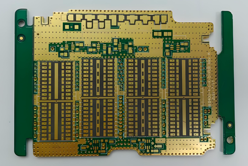
High Frequency PCB
Key Differences Between RF PCB vs. High Frequency PCB
| Aspect | High-Frequency PCB | RF PCB |
| Definition | Boards operating at high digital or analog frequencies | Boards designed specifically for RF signal transmission |
| Signal Range | 500 MHz–10 GHz+ | 300 MHz–300 GHz |
| Design Focus | Signal integrity, low loss | Electromagnetic control, transmission lines, matching |
| Material | Rogers 4000 series, Isola, Panasonic Megtron | PTFE, RO3003/5880, ceramic-filled laminates |
| Impedance Control | Important | Critical (tighter tolerance) |
| Manufacturing Difficulty | Medium | High |
| Typical Use | Wi-Fi, Bluetooth, high-speed digital | Radar, RF amplifiers, filters, GNSS, mmWave |
When Are They “the Same PCB”?
A design can fall under both categories when:
- The signal is RF (e.g., 2.4 GHz, 5.8 GHz)
- The designer uses high-frequency materials
- The board contains microstrip, CPW, filters, or antennas
For example, a 2.4 GHz RF transceiver board using RO4350B is simultaneously:
- a high-frequency PCB, because frequency is high
- an RF PCB, because it processes RF signals
Thus, overlap exists, but they are not inherently identical.
Which One Should You Specify to Your PCB Supplier?
If your project handles RF transmission, always specify RF PCB so the manufacturer focuses on:
- surface roughness control (Ra < 2 µm for low loss)
- uniform dielectric thickness
- controlled resin flow during lamination
- tighter etching tolerance
- Dk matching for microstrip/CPW accuracy
If it is only high-speed digital (e.g., PCIe, SerDes), then choose high-frequency PCB.
Why Do RF PCBs Need Special Materials Compared with High Frequency PCBs?
Material behavior influences both categories. Yet an rf pcb is more sensitive to the dielectric constant and copper profile.
RF units run energy through transmission lines. If the copper roughness increases loss, the system sees reduced range or gain shift. If the Dk drifts, the phase response moves. Because of this, the most common materials for rf pcb work include RO3003, RO4350B, RO5880, and PTFE blends.
In contrast, high frequency pcb materials can include Megtron series or Rogers 4000 series because the signal shape is less sensitive to phase stability. They still target low loss, but their working window is wider.
What Frequencies Define RF PCB Work vs High Frequency PCB Work?
Both ranges relate to how the signal behaves. RF work usually starts at 300 MHz and goes up to millimeter-wave. This includes radar, satellite, GPS, 24 GHz and 77 GHz systems, and many short-range radios.
High frequency ranges start from about 500 MHz to beyond 10 GHz. These support fast digital buses, Wi-Fi, and mixed-signal designs.
However, the frequency alone does not decide the board’s category. The final system function does.
Do RF PCBs Always Cost More Than High Frequency PCBs?
Actually yes when under the same design. RF boards use premium materials. These materials cost more because they hold stable Dk, low loss, and a smooth copper surface. They also require strict process control during drilling, plating, and lamination.
High frequency boards may use moderate-cost materials such as RO4003C or Megtron 4. They also need controlled lamination, yet the window for yield is wider.
Costs also rise when an rf pcb uses fine lines, tight impedance, or stacked microstrip structures. That said, skilled manufacturers can keep RF costs under control by optimizing stackup and process flow.
What Problems Occur When Designers Use the Wrong PCB Type?
If a design intended for RF is built on a standard high frequency pcb, several issues may appear:
- Reduced communication range
- Higher insertion loss
- Unstable gain
- Incorrect antenna tuning
- Phase delay changes
- EMC issues
Although not every situation is severe, these issues waste time in testing and rework.
When a high frequency digital board is produced using strict RF rules, the design remains stable. Yet the cost often rises without a visible performance gain.
What Tests Are Important for RF PCBs Compared with High Frequency PCBs?
RF boards often need tests beyond regular PCB checks. These include:
- Dielectric thickness check
- Dk variation review
- Copper profile check
- TDR impedance scan
- S-parameter review after assembly
High frequency boards may also use TDR scans, yet the tolerance is wider. For RF, every shift affects the final device.
How Does EBest Circuit (Best Technology) Support RF PCB and High Frequency PCB Projects?
EBest Circuit (Best Technology) offers full material guidance, stackup review, transmission line advice, and strong quality assurance for both rf pcb and high frequency pcb builds. We handle small prototype lots and volume orders with the same care. Each rf pcb passes a detailed review, so the final product meets the performance target.
Our strengths include:
- ISO9001, ISO13485, IATF16949, and AS9100D systems
- Complete MES traceability
- Tight impedance control
- Fine etching for RF lines
- Skilled process teams for PTFE and hybrid stackups
- Smooth copper profile management
- Fast prototype to mass build for global clients
We support antenna work, radar modules, filters, amplifiers, and mixed-signal boards. Our engineering team reviews each design before production to catch layout risks early to speed up product launches. For your next RF or high frequency project, our team stands ready to guide you from concept to delivery!
FAQs
1. Is an rf pcb the same as a high frequency pcb?
No. All RF boards are high frequency boards, but not all high frequency boards meet RF conditions.
2. Can I use RO4003C for both RF and high frequency PCB use?
Yes. However, many RF systems still need lower-loss materials such as RO3003 or RO5880.
3. Are RF boards harder to build?
Yes. They need tighter process control, smoother copper, and stable lamination.
4. How do I know if my design needs an rf pcb?
If your design uses antennas, filters, couplers, or PA modules, you need an RF board.
5. Does EBest Circuit (Best Technology) support RF and high frequency PCBA work?
Yes. We handle full assembly, tuning, connector installation, and testing.
Tags: high frequency pcb, high frequency pcb supplier, RF PCB, RF PCB Manufacturer, rf pcb material