

What Is the IPC-TM-650 Test Methods Manual?
IPC-TM-650 test methods manual is a collection of standardized test procedures used to evaluate printed circuit boards, PCB materials, assemblies, and connectors. It helps PCB manufacturers, quality engineers, and buyers use the same technical language when discussing cleanliness, plating quality, solder mask reliability, electrical insulation, environmental stress, and mechanical stability.
In simple words, IPC-TM-650 tells people how to test a PCB-related item. It does not always tell people whether the result is acceptable for every project. The pass/fail requirement often comes from customer specifications, IPC product standards, procurement documents, or industry-specific quality requirements.
For PCB production, IPC-TM-650 is often used for:
- PCB cleanliness verification
- Bow and twist measurement
- Solder mask reliability testing
- Microsection analysis
- Surface insulation resistance testing
- CAF resistance evaluation
- Thermal stress and thermal shock testing
- Material electrical and mechanical property checks
Why Is IPC-TM-650 Important for PCB Manufacturing Quality?
IPC-TM-650 is important because it gives PCB manufacturers and customers a consistent way to verify quality. Without a shared test method, one supplier may test cleanliness in one way, another may use a different extraction method, and a customer may struggle to compare results fairly.
It supports quality control in several practical areas:
- Process control: checking whether manufacturing steps remain stable from batch to batch
- Failure analysis: identifying the possible cause of leakage, corrosion, delamination, or solder mask failure
- Supplier qualification: checking whether a PCB supplier can meet reliability expectations
- Design verification: confirming that stack-up, materials, hole structure, and solder mask choices fit the application
- High-reliability production: supporting medical, automotive, aerospace, telecom, power electronics, and industrial control projects
A PCB factory that understands these testing methods can usually communicate better during DFM review, material selection, production validation, and quality troubleshooting.
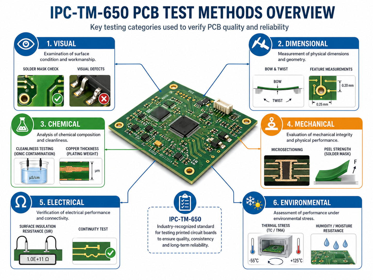
What Test Categories Are Included in IPC-TM-650?
IPC-TM-650 covers multiple test categories, including visual, dimensional, chemical, mechanical, electrical, environmental, and connector-related test methods. These categories help users quickly find the right method for a specific quality concern.
| IPC-TM-650 Category | Main Test Focus | PCB Manufacturing Relevance | Typical Examples |
|---|---|---|---|
| Visual Test Methods | Internal and external observation | Helps inspect plating, holes, laminate structure, and visible defects | Microsectioning, plated-through hole evaluation |
| Dimensional Test Methods | Size, thickness, flatness, hole position | Helps control board geometry and assembly fit | Bow and twist, thickness, hole location |
| Chemical Test Methods | Residues, contamination, chemical properties | Helps evaluate cleanliness and process residues | ROSE, ion chromatography, organic contamination |
| Mechanical Test Methods | Strength, adhesion, peel, material behavior | Helps validate copper adhesion, solder mask durability, and flexible material strength | Peel strength, adhesion, abrasion |
| Electrical Test Methods | Resistance, dielectric strength, signal performance | Helps evaluate insulation, high-voltage behavior, and RF properties | SIR, dielectric strength, impedance-related tests |
| Environmental Test Methods | Humidity, heat, thermal cycling, aging | Helps predict long-term reliability under service conditions | Thermal shock, CAF, moisture resistance |
| Connector Test Methods | Connector durability and electrical behavior | Helps validate connector-level reliability | Contact resistance, vibration, humidity |
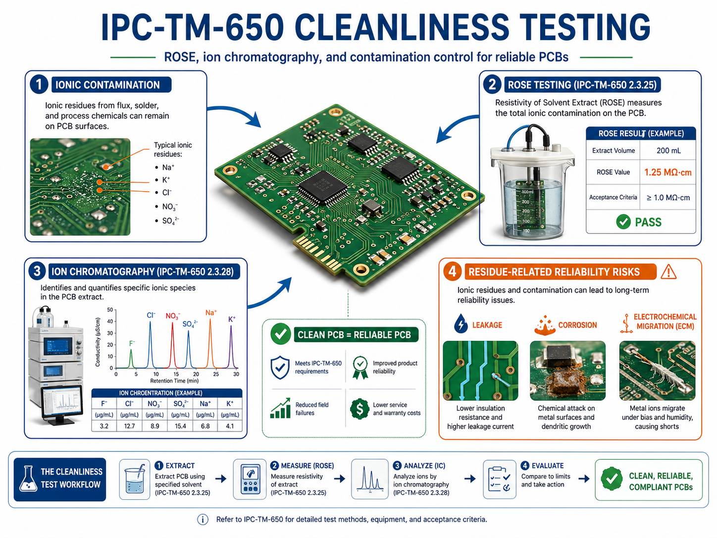
What Is IPC-TM-650 Cleanliness Testing?
IPC-TM-650 cleanliness testing evaluates contamination, ionic residues, flux residues, process chemicals, and other materials that may remain on a PCB or PCBA surface. In PCB manufacturing, cleanliness is closely linked to insulation resistance, corrosion resistance, electrochemical migration, and field reliability.
Cleanliness is especially important when a board works in:
- High humidity
- High voltage
- High impedance circuits
- Medical monitoring equipment
- Automotive control modules
- Industrial sensors
- Telecom infrastructure
- Aerospace or defense electronics
A small amount of ionic residue may not create an immediate failure during final electrical testing. However, when moisture, voltage bias, and time are added, residues can support leakage paths, dendritic growth, corrosion, and unstable electrical behavior.
IPC-TM-650 includes methods related to cleanliness and insulation performance, including surface insulation resistance and bare board cleanliness by SIR in the approved environmental test method list.
| Cleanliness-Related Test | What It Checks | Best Used For | Practical Value |
|---|---|---|---|
| ROSE Test | Overall ionizable surface contamination | Routine process control | Fast cleanliness screening |
| Ion Chromatography | Specific ionic species and concentration | Failure analysis and high-reliability projects | Finds contamination source more precisely |
| SIR Test | Insulation behavior under humidity and electrical bias | Cleanliness validation under stress | Shows reliability impact of residues |
| Visual Inspection | Visible residue, staining, white marks, process contamination | Initial quality screening | Simple but not enough alone |
| Process Audit | Cleaning chemistry, rinse quality, drying, handling | Manufacturing control | Helps prevent repeat issues |
What Is IPC-TM-650 2.3.25 ROSE Testing for PCB Cleanliness?
IPC-TM-650 2.3.25 ROSE testing is commonly used to evaluate ionizable surface contaminants on PCB or PCBA surfaces. ROSE stands for Resistivity of Solvent Extract. It gives a fast cleanliness indicator, often reported as sodium chloride equivalent per unit area.
ROSE testing is useful because it is fast, repeatable, and suitable for production monitoring. If a PCB factory needs to compare different batches, check a cleaning process, or monitor contamination trends, ROSE can provide a practical baseline.
However, ROSE testing has a limitation. It measures total ionizable contamination, but it does not identify every individual ion. For example, a high ROSE reading may suggest contamination, but it may not tell whether the issue comes from chloride, bromide, weak organic acids, sodium, plating chemistry, flux residue, or handling contamination.
That is why ROSE is often used as a process control tool, while ion chromatography is used when a more detailed contamination profile is needed.
Good use cases for ROSE testing include:
- Routine PCB cleanliness monitoring
- PCBA cleaning process validation
- Supplier quality comparison
- Batch-to-batch contamination trend review
- Quick screening before deeper analysis
For high-reliability products, ROSE alone may not be enough. It should be combined with ion chromatography, SIR, process traceability, and application-specific acceptance criteria.
What Is IPC-TM-650 2.3.28 Ion Chromatography Testing?
Ion chromatography is a more detailed cleanliness analysis method because it can identify and quantify specific ionic species. While ROSE gives an overall contamination value, ion chromatography helps show what type of contamination is present.
This matters in real PCB failure analysis. A board may show leakage current, corrosion, or dendritic growth after field use. A general contamination number may confirm that residue exists, but it may not explain the source. Ion chromatography can help identify whether the residue is related to process chemistry, flux activators, handling, water quality, or environmental exposure.
Typical ions that may be evaluated include:
- Chloride
- Bromide
- Sulfate
- Nitrate
- Sodium
- Potassium
- Weak organic acids
- Other process-related ionic species
Ion chromatography is especially valuable for medical electronics, automotive electronics, aerospace electronics, high-voltage PCB, and precision sensor circuits. In these products, contamination is not only a cosmetic concern. It can become a long-term electrical reliability risk.
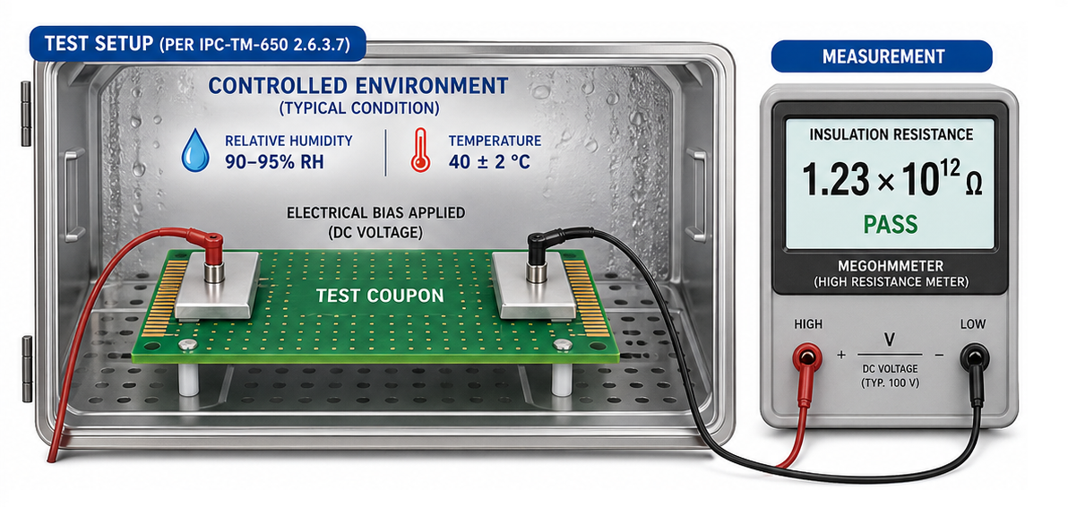
What Is IPC-TM-650 2.6.3.7 Surface Insulation Resistance Testing?
IPC-TM-650 2.6.3.7 surface insulation resistance (SIR) testing evaluates how well a PCB surface maintains electrical insulation under humidity, temperature, and electrical bias.
SIR testing is important because many contamination problems do not appear during normal room-temperature inspection. A board may pass final electrical testing immediately after production. But after exposure to moisture and voltage bias, residues may become conductive enough to reduce insulation resistance.
The official IPC TM-650 method list includes TM 2.6.3.7 as “Surface Insulation Resistance.”
In practical PCB production, SIR testing can help evaluate:
- Whether a cleaning process is reliable
- Whether solder mask materials maintain insulation under humidity
- Whether residues create leakage paths
- Whether no-clean flux residues are acceptable for the application
- Whether high-impedance circuits will remain stable over time
- Whether bare boards or assemblies are suitable for harsh environments
SIR should be considered when a PCB uses dense spacing, fine-pitch components, high voltage, no-clean processes, or sensitive analog circuits. It is also useful when qualifying a new solder mask, flux, cleaning process, or assembly supplier.
What Is IPC-TM-650 Bow and Twist Testing?
IPC-TM-650 bow and twist testing is used to evaluate PCB flatness. Bow refers to a board bending in a smooth curved shape, while twist refers to diagonal warpage where the corners are not on the same plane.
| Flatness Issue | What It Looks Like | Main Assembly Risk | Common Design or Process Cause |
|---|---|---|---|
| Bow | Board bends like a shallow arc | Uneven solder paste transfer, placement offset | Thin board, large panel, unbalanced copper |
| Twist | Board corners lift diagonally | Connector misalignment, BGA open joints | Asymmetric stack-up, laminate stress |
| Local Warpage | One area lifts or deforms | Fine-pitch soldering defect | Local copper imbalance or heat concentration |
| Panel Warpage | Full production panel bends | Routing, depaneling, and handling issues | Panel size, material stress, thermal exposure |
Bow and twist control is especially important for:
- Thin PCB
- Large-size PCB
- HDI board
- BGA assembly
- Fine-pitch QFN and LGA packages
- Press-fit connector boards
- Automotive control boards
- LED panels
- Rigid-flex boards
- Boards with uneven copper distribution
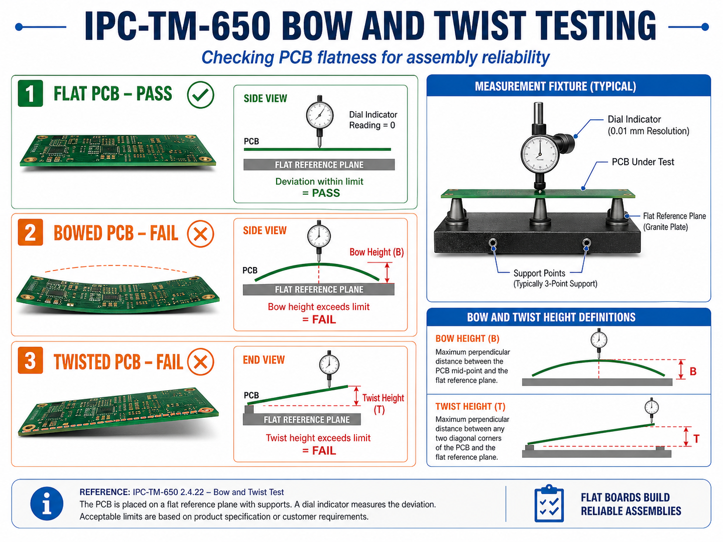
How Does Bow and Twist Affect PCB Assembly Reliability?
Excessive bow and twist can reduce assembly yield and long-term solder joint reliability. A PCB may still pass bare board electrical testing, but poor flatness can create serious problems during SMT assembly.
During solder paste printing, a warped board may not contact the stencil evenly. This can create insufficient solder paste in some areas and excess paste in others. During placement, small chip components may sit at different heights. During reflow, BGA or QFN packages may not maintain uniform contact with solder deposits.
The risks become more serious as component pitch becomes smaller. Common reliability problems caused by poor flatness include:
- Open solder joints
- Insufficient solder fillet
- BGA non-wet open defects
- Connector seating failure
- Uneven mechanical stress after assembly
- Housing fit problems
- Local solder cracking during field vibration
- Lower first-pass assembly yield
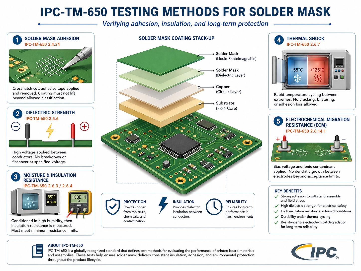
What Are IPC-TM-650 Testing Methods for Solder Mask?
IPC-TM-650 testing methods for solder mask help evaluate whether the solder mask can protect copper, maintain insulation, resist humidity, withstand thermal stress, and support long-term PCB reliability.
Solder mask is more than the green, blue, black, white, or red coating seen on a finished PCB. It protects copper traces, defines solderable areas, reduces solder bridging, and supports electrical insulation between conductors.
Poor solder mask performance can cause:
- Solder bridging
- Copper exposure
- Mask peeling
- Blistering
- Cracking after reflow
- Chemical attack from cleaning agents
- Leakage under humidity
- Electrochemical migration risk
The IPC TM-650 method list includes solder-mask-related methods such as solder mask dielectric strength, solder mask moisture and insulation resistance, solder mask thermal shock, solder mask hydrolytic stability, and solder mask resistance to electrochemical migration.
How Is IPC-TM-650 Different from IPC-A-600, IPC-6012, and IPC-A-610?
IPC-TM-650 explains how to test, while other IPC documents often define what is acceptable. This difference is important because many buyers ask for “IPC standard” without knowing which document applies to the problem.
| Document | Main Purpose | Simple Explanation | Common Use |
|---|---|---|---|
| IPC-TM-650 | Test methods manual | Explains how to perform tests | Cleanliness, SIR, bow and twist, solder mask tests |
| IPC-A-600 | Acceptability of printed boards | Shows acceptable and non-acceptable bare board conditions | Visual inspection of bare PCBs |
| IPC-6012 | Performance specification for rigid PCBs | Defines rigid PCB performance requirements | Rigid board procurement and quality control |
| IPC-A-610 | Acceptability of electronic assemblies | Defines PCBA workmanship acceptance | SMT assembly and solder joint inspection |
| Customer Specification | Project-specific acceptance requirement | Defines what the customer expects | Special reliability, materials, and reporting needs |
Which IPC-TM-650 Test Methods Should You Choose for Your PCB Project?
The right IPC-TM-650 test depends on the product application, failure risk, PCB structure, operating environment, and customer requirement. A simple consumer board does not always need the same test plan as a medical, automotive, aerospace, or power electronics PCB.
The goal is not to order every possible test. The goal is to choose the tests that reduce the most relevant risk.
| PCB Project Type | Recommended IPC-TM-650 Related Tests |
|---|---|
| HDI PCB | Microsectioning, CAF, SIR, thermal stress |
| Automotive PCB | Bow and twist, CAF, thermal cycling, SIR |
| Medical PCB | Cleanliness, ion chromatography, SIR, traceability report |
| RF PCB | Dk/Df, signal loss, dimensional stability |
| Power PCB | Dielectric strength, thermal stress, CAF, solder mask insulation |
| Rigid-Flex PCB | Peel strength, bend reliability, microsectioning |
| Fine-Pitch SMT PCB | Bow and twist, solder mask registration, cleanliness |
| Solder Mask Critical PCB | Solder mask dielectric strength, moisture resistance, thermal shock |
For early-stage prototypes, microsectioning and basic dimensional checks may be enough. For mass production, the test plan should be more structured.
How Should You Read an IPC-TM-650 Test Report?
A useful IPC-TM-650 test report should show more than a pass/fail result. It should tell the reader which method was used, how the sample was prepared, what condition was applied, what result was measured, and how that result connects to the project requirement.
A weak report says, “Passed.” While a strong report explains the evidence.
When reviewing an IPC-TM-650 test report, check the following items:
- Test method number
- Test method revision
- Sample name and part number
- Production lot number
- Material type and stack-up
- Surface finish
- Sample quantity
- Test condition
- Test duration
- Equipment used
- Calibration status
- Measurement result
- Acceptance criteria source
- Photos, charts, or microsection images
- Technician or engineer review
- Final conclusion
- Traceability information
For high-value PCB projects, test reports should be stored as part of the quality record. They may become important during customer audits, field failure review, design changes, and supplier qualification.
How to Choose a PCB Manufacturer with IPC-TM-650 Testing Capability?
A capable PCB manufacturer should understand IPC-TM-650 as a practical quality tool, not just a document name. The supplier should know which test applies, when it should be used, what result format is expected, and how the result affects manufacturing decisions.
When selecting a PCB supplier, ask specific questions. Do not only ask, “Can you make IPC-quality boards?”
Ask:
- Can you provide IPC-TM-650 cleanliness testing support?
- Can you measure bow and twist for thin or large-size boards?
- Can you support solder-mask-related reliability testing when needed?
- Can you provide microsection images for plated holes and microvias?
- Can you support SIR or CAF testing for high-reliability products?
- Can you link test results to production lots and material batches?
- Can your engineering team review stack-up, copper balance, and process risks before production?
- Can you explain whether a test result meets our project-specific requirement?
A strong supplier will not recommend unnecessary testing just to increase cost. Instead, the supplier should help match the test plan to the project risk.
For example, a simple 2-layer prototype may need only basic electrical test and visual inspection. A 12-layer automotive control board may need microsectioning, thermal stress, CAF review, cleanliness control, and bow and twist monitoring. A medical sensing PCB may require cleanliness testing, SIR validation, and strict traceability.
Testing capability is part of reliability. Engineering judgment is the other part.
FAQs About IPC-TM-650 Test Methods
1. What is the IPC-TM-650 test methods manual?
IPC-TM-650 test methods manual is a collection of standardized testing procedures for printed circuit boards, materials, assemblies, and connectors. It covers visual, dimensional, chemical, mechanical, electrical, environmental, and connector-related testing. It helps PCB manufacturers and customers evaluate quality using consistent methods.
2. Is IPC-TM-650 the same as IPC-A-600?
No. IPC-TM-650 explains how to perform PCB-related tests. IPC-A-600 focuses on the acceptability of printed boards. In simple words, IPC-TM-650 is about testing procedures, while IPC-A-600 is about inspection and acceptance of bare PCB conditions.
3. When should I request IPC-TM-650 testing from a PCB supplier?
You should request IPC-TM-650 testing when your PCB has reliability-sensitive requirements, such as high voltage, fine spacing, high impedance, medical use, automotive use, harsh environment exposure, strict cleanliness needs, or complex multilayer construction. It is also useful during supplier qualification and failure analysis.
4. Does every PCB project need IPC-TM-650 testing?
Not every PCB project needs the full range of IPC-TM-650 testing. A simple prototype may only need basic inspection and electrical test. High-reliability boards, dense HDI boards, medical electronics, automotive electronics, power boards, and RF boards often need a more complete test plan.
You may also like


Tags: ipc-tm-650, ipc-tm-650 2.6.3.7 surface insulation resistance, ipc-tm-650 testing methods for solder mask