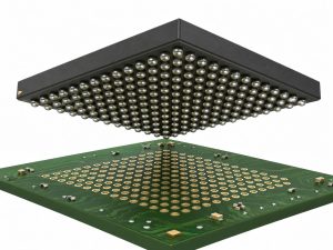
A head-in-pillow defect occurs when a BGA solder ball and the printed solder paste fail to join properly during reflow. The two solder masses may touch, allowing the board to pass an electrical test, while the joint remains mechanically weak. This makes HIP especially troublesome in assemblies that work initially but develop intermittent connections during handling, temperature changes, or service.
EBest Circuit (Best Technology) supports BGA assembly with solder paste inspection, reflow soldering, and X-ray inspection. These capabilities help connect hidden solder-joint problems with the printing and assembly processes that influence them. For a BGA build affected by recurring soldering defects, contact sales@bestpcbs.com to discuss the assembly process and inspection approach.
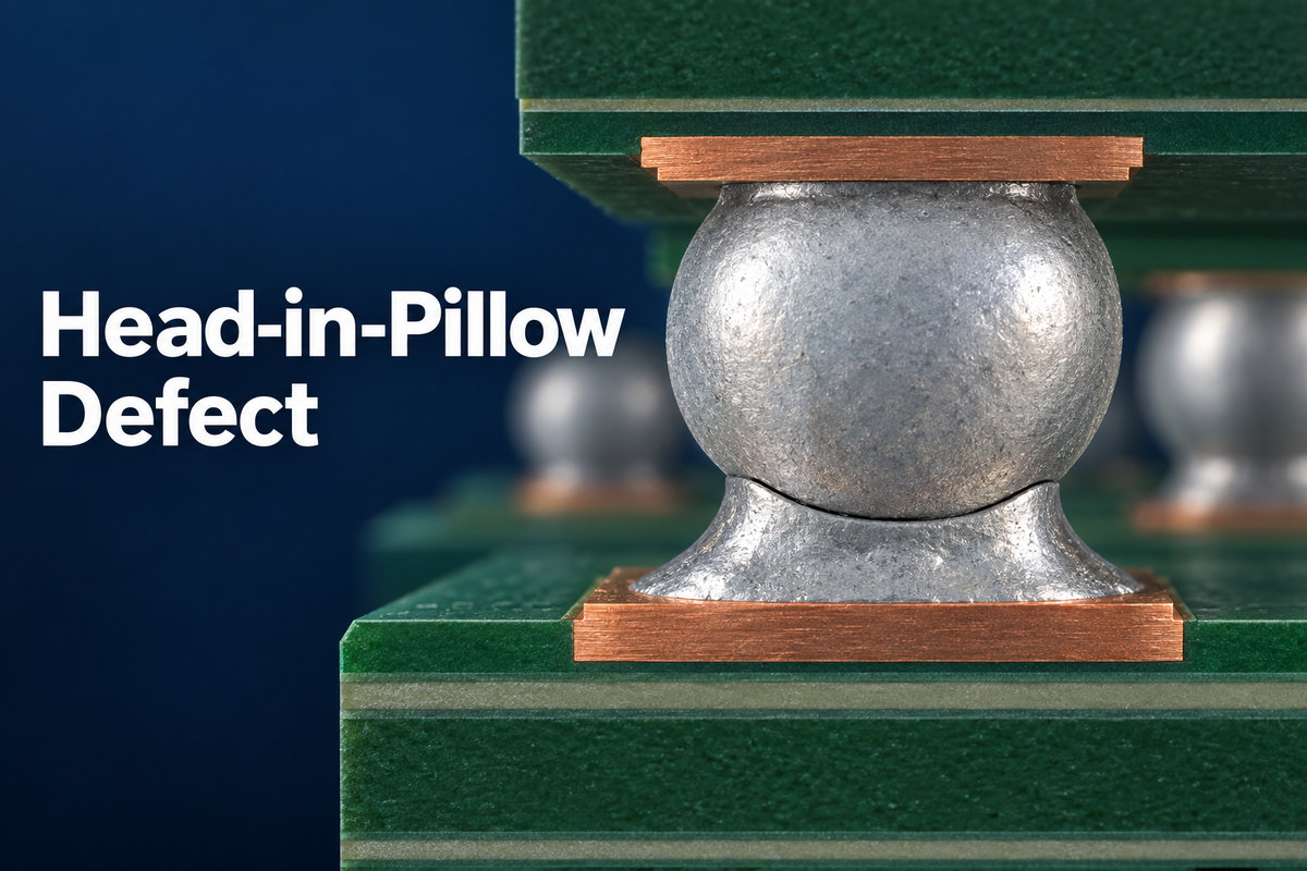
What Is a Head-in-Pillow Defect?
A head-in-pillow defect is an incompletely joined interface between the component's solder ball and the reflowed solder paste on the PCB. The paste may have wetted the copper land correctly, yet failed to merge with the ball above it. In a section through the joint, the ball can resemble a head resting on a pillow of solder.
Physical contact does not establish a sound solder joint. A reliable connection requires the solder surfaces to wet and coalesce. If an oxide film or other wetting barrier remains between them, the contact can conduct electricity without providing the strength expected from a properly formed joint.
The resulting failure may be an immediate open circuit or an intermittent connection. Temperature changes or mechanical movement can disturb that contact and expose the weakness. However, these symptoms alone do not identify HIP: cracked joints, damaged pads, and other BGA defects can produce similar behavior.
What Causes a Head in Pillow Defect During Reflow?
HIP develops when the solder ball and paste fail to maintain or recover the contact and wetting conditions needed to merge. Dynamic warpage is one important trigger, but oxidation, contamination, paste behavior, and flux activity also influence the outcome.
A typical warpage-related sequence is:
- Initial contact: Placement brings the BGA balls into contact with the printed paste deposits.
- Temporary separation: As the assembly heats, the package or PCB changes shape. Some balls lift away from their deposits.
- Separate reflow and oxidation: The paste reflows on the land while the separated surfaces remain exposed. Oxide films can interfere with subsequent wetting.
- Incomplete reunion: The package moves back toward the board, but renewed contact does not produce full coalescence if the interface is no longer wettable or the solder has solidified.
This explains why a package that appears flat after cooling can still contain defective joints. Its final shape does not reveal how it moved while the solder was forming.
Warpage is not the only route to HIP. Oxidized or contaminated solder balls can resist wetting even when their initial contact with the paste is adequate. Flux must remove surface oxides and protect the interface during the useful soldering period; the presence of flux residue after reflow does not prove that sufficient activity remained when the ball and paste needed to join.
Defects concentrated near BGA corners can suggest package movement or temperature differences. That pattern is a diagnostic clue, not proof of a single cause.
How Does a Head on Pillow Defect Differ from a Non-Wet Open?
Head on pillow, also called HoP, describes the same general defect family as head-in-pillow. The important distinction from a BGA non-wet open is where the connection fails to form.
| Feature | Head-in-pillow / head on pillow | BGA non-wet open |
|---|---|---|
| Main failed interface | Between the solder ball and reflowed paste | Between the solder and PCB land |
| Typical solder distribution | Separate solder masses remain on the component and board sides | Paste can join the component ball and pull away from the land |
| Main diagnostic question | Did the ball and paste coalesce? | Did the solder wet the PCB land? |
In the non-wet-open mechanism described here, solder can accumulate on the component side while the PCB land remains unwetted. HIP can leave solder attached to the land, with the defective interface above it.
Both conditions may produce an open or unstable electrical connection, but they direct the investigation toward different interfaces. A dark line, unusual ball shape, or failed continuity test cannot establish that distinction by itself. Examination of the affected joint must locate the actual separation or wetting failure.
Why Can a Head-in-Pillow Defect Escape Inspection?
HIP can escape inspection because the failed interface is hidden and may still make electrical contact. Different inspection methods reveal different parts of that problem.
Visual inspection and AOI have limited access. Most BGA joints sit beneath the package. AOI can identify placement errors and visible assembly defects, but it cannot establish the integrity of every hidden ball-to-paste interface.
Electrical testing captures the connection under the test conditions. A weak interface may touch well enough to pass continuity or functional testing. If the contact changes with temperature or movement later, the failure appears after the test has finished. Passing once therefore does not demonstrate that the solder masses have formed a reliable joint.
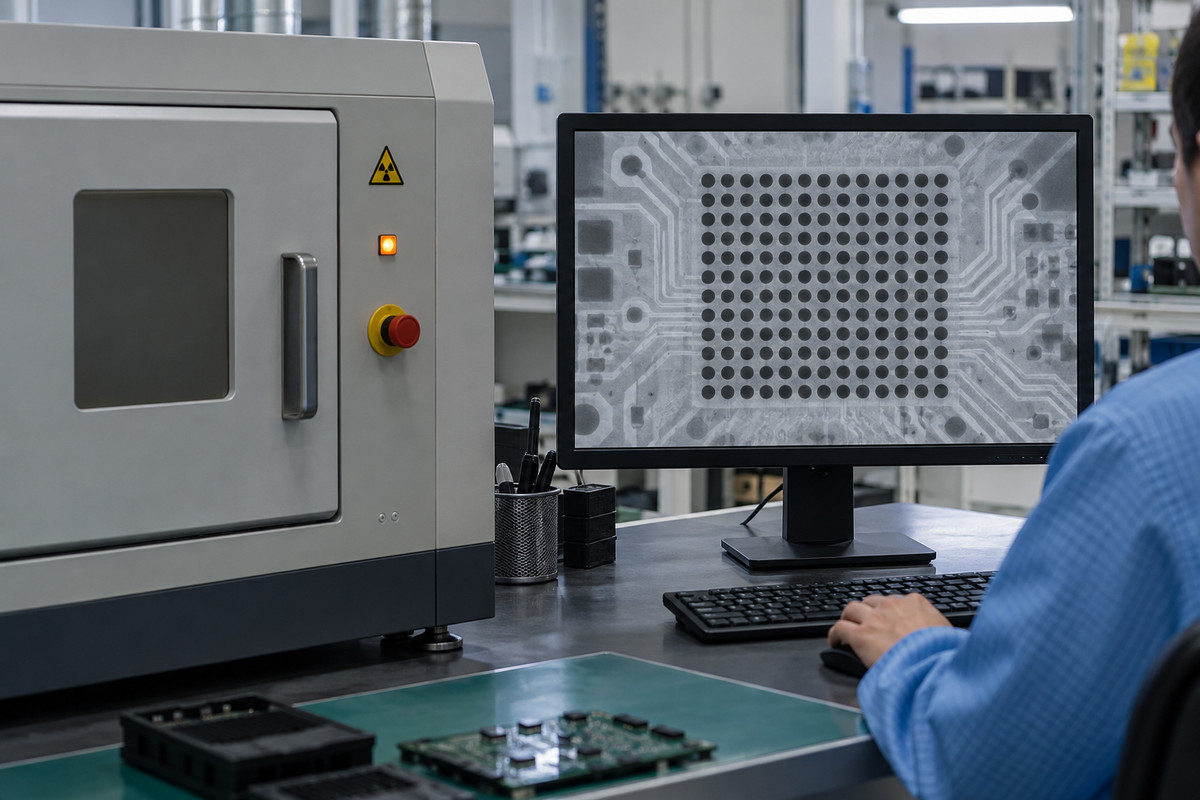
X-ray images require careful interpretation. A top-down image projects the joint through its thickness, so two touching but incompletely joined solder masses can overlap in the image. Oblique views or suitable three-dimensional imaging may reveal separation or unusual joint geometry more clearly. However, a narrow waist or suspicious outline is not, by itself, proof of HIP; joint shape can also create misleading indications.
When electrical symptoms and X-ray findings disagree, further failure analysis may be needed. Cross-sectioning or a controlled dye-and-pry investigation can provide additional evidence, although these methods are destructive and depend on preparation and interpretation. Such analysis is most useful when it targets the suspected location and is correlated with the original failure.
Inspection can identify suspect joints and support diagnosis. Preventing their formation still depends on controlling the assembly process.
How Do Solder Paste and Stencil Printing Affect HIP Risk?
Solder paste affects HIP through both contact geometry and wetting behavior. The printed deposit must reach the ball consistently, while the flux must remain effective during joint formation.
A low or uneven deposit can leave less contact margin when a package moves during reflow. Deposit height matters alongside volume: paste that spreads or slumps can contain solder but provide less vertical contact with the ball. Printing offset can also reduce the contact area between the ball and its intended deposit.
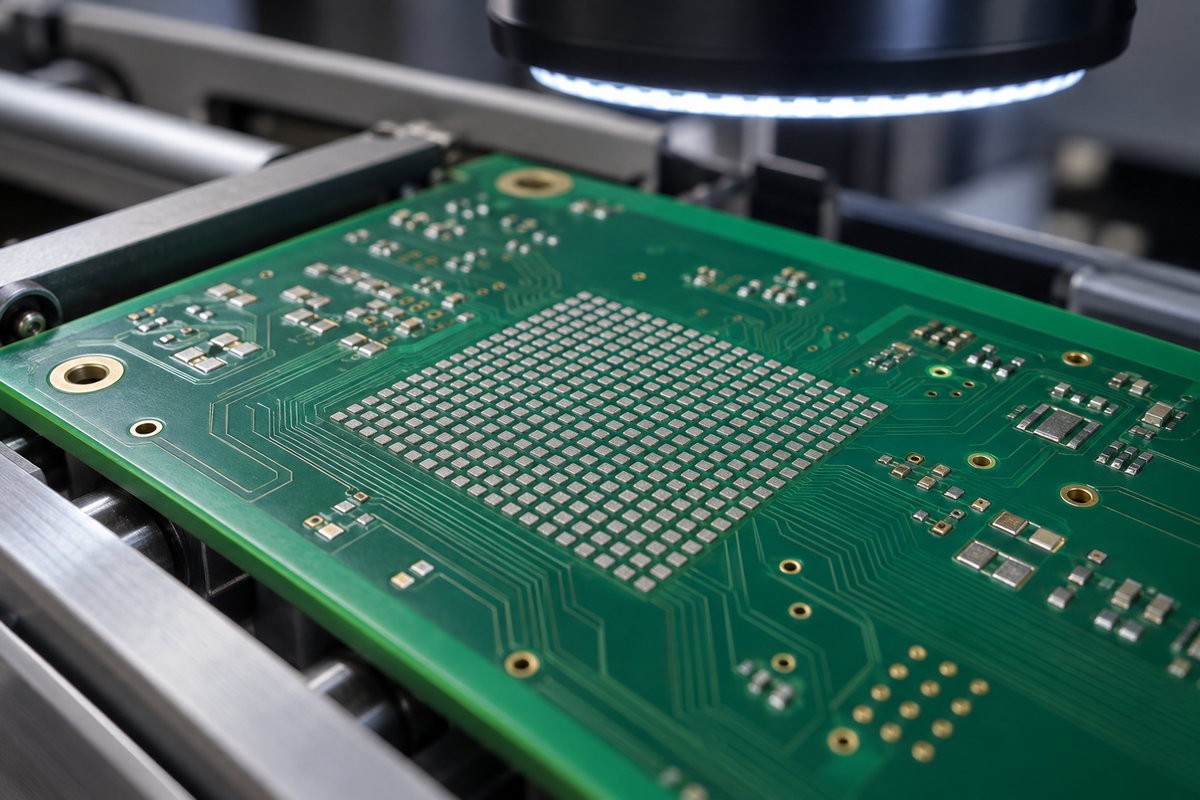
SPI helps reveal insufficient deposits, height variation, and printing misalignment before placement. Comparing the affected BGA locations with their print measurements can show whether the defect follows a printing problem. Consistent deposits at failing locations, however, leave package movement and wetting behavior as important possibilities.
Increasing stencil aperture size is not a universal correction. Additional paste may improve contact in a particular process, but too much can introduce bridging or alter joint geometry. The useful adjustment is one that improves deposit consistency and contact without creating another defect.
Flux chemistry also matters. Paste behavior during heating, oxide removal, and protection against further oxidation influence whether separated surfaces can join again. A paste that prints well at room temperature may still need evaluation under the actual BGA reflow conditions. HIP reduction therefore requires both a suitable material and a repeatable printing process.
Can a Hotter Reflow Profile Eliminate HIP?
No. A hotter profile can help when inadequate heating is the problem, but it can also increase warpage, oxidation, or flux depletion. Temperature alone cannot ensure that the ball and paste remain in contact and wet each other.
The relevant temperature is the one experienced by the assembly, not simply the oven setpoint. A large BGA and the surrounding PCB can heat unevenly. Raising the oven temperature to correct a colder location may expose another part of the assembly to excessive heat.
The timing matters as well. Solder must reach the required reflow conditions while enough flux activity remains to support wetting. A prolonged heating cycle may consume that activity before difficult interfaces have joined. A profile that is too short or too cool can leave inadequate wetting or reflow at the coldest joints.
Useful profiling therefore considers temperature differences across the package, peak temperatures, and time above the relevant alloy's liquidus. Thermocouple measurements at representative locations help show how the assembly actually heats. The acceptable window must also respect the solder paste guidance and component temperature limits.
If the underlying problem is severe package movement or a poorly wettable ball surface, profile changes alone may not resolve it. Paste, component condition, and thermal behavior have to be considered together.
Can a Head-in-Pillow Defect Be Repaired?
An assembly affected by HIP can often be recovered through controlled BGA rework, provided the PCB lands and surrounding structure remain suitable for repair. Simply reheating the package until the board works again does not establish that the defective interface has been corrected.
Rework may involve removing the affected component, preparing the PCB lands, applying fresh solder paste, and attaching an appropriate replacement device under a characterized thermal profile. Removal and replacement both need controlled heating to avoid pad damage, excessive board deformation, or package damage.
Component reuse depends on the device supplier's restrictions and the condition of the removed part. Reballing is not automatically necessary or permitted, and it cannot repair damage inside a component or beneath a PCB land.
If the original failure still needs investigation, relevant observations should be preserved before rework changes the joint. After repair, inspection and electrical verification must address the repaired site and the original symptom. A successful repair also needs the cause of the first failure addressed; otherwise, the replacement process can reproduce the same defect.
How Can EBest Circuit Help Reduce HIP Risk?
EBest Circuit supports HIP risk reduction through BGA assembly, solder paste inspection, reflow process control, and X-ray inspection of hidden joints. The value comes from connecting these stages: a soldering problem found after reflow can be compared with the paste deposits and assembly conditions that preceded it.
The relevant capabilities include:
- SPI: Identifies paste deposition problems that can reduce consistent ball-to-paste contact.
- BGA placement and reflow soldering: Support accurate assembly and thermal processing matched to the board and component requirements.
- Air and nitrogen reflow capability: Allows the atmosphere to be considered alongside paste and profile requirements where oxidation is a concern.
- X-ray inspection: Provides information about hidden joint geometry and helps identify locations needing further investigation.
For a new BGA build, these controls help address soldering conditions before production expands. For a recurring defect, they help narrow whether printing, thermal behavior, or the soldering interface needs attention. Ambiguous inspection findings may still require further analysis before the failure mechanism is established.
The assembly approach should fit the affected package and board. A generic hotter profile or larger stencil aperture cannot replace that process understanding.
FAQs About Head-in-Pillow Defect
1. Are HIP and HoP different defects?
HIP usually means head-in-pillow, while HoP means head on pillow. Both commonly describe incomplete joining between a component's solder ball and reflowed paste. Terminology can vary, so the failed interface is more useful than the abbreviation when discussing a diagnosis.
2. Does HIP occur only with lead-free solder?
No. HIP is strongly associated with lead-free BGA assembly, but the underlying problem is incomplete wetting and coalescence. Using a tin-lead process does not by itself guarantee that the ball and paste will form a sound joint.
3. Can nitrogen reflow completely prevent HIP?
No. Nitrogen can reduce oxidation during reflow, but it does not remove package warpage, correct an insufficient paste deposit, or guarantee wetting of an already contaminated surface. It is one process variable, not a complete prevention method.
4. Will adding more solder paste solve the problem?
Only when inadequate deposition or contact is a contributing cause and the change remains suitable for the joint geometry. More paste cannot reliably compensate for poor solderability or excessive package movement, and excessive deposits can create bridging.
5. Is a solder void the same as a head-in-pillow defect?
No. A void is a cavity within the solder. HIP is a failure of the ball and paste to join properly at their interface. Both can occur in BGA assemblies, but they require different interpretation and corrective action.
For help reducing head-in-pillow defect risk in your next BGA assembly, contact sales@bestpcbs.com. EBest Circuit can discuss the printing, reflow, and inspection approach for your board, including how to investigate recurring hidden-joint failures.