A DPDT relay diagram helps engineers understand how a double pole double throw relay switches two independent circuits at the same time. It is commonly used for polarity reversal, motor direction control, signal switching, power path selection, and industrial control boards.
For PCB and PCBA projects, however, understanding the diagram is only the first step. The relay must also match the PCB footprint, coil voltage, contact rating, creepage and clearance, soldering process, thermal requirement, and test method. EBest Circuit (Best Technology) supports PCB fabrication, BOM review, component sourcing, SMT and through-hole assembly, DFM checking, and functional test coordination for relay control PCB and PCBA projects. If you are preparing a relay board, control PCB, or assembled PCBA, please send your Gerber files, BOM, drawings, datasheets, and assembly notes to sales@bestpcbs.com for review before production.
How to Read a DPDT Relay Diagram
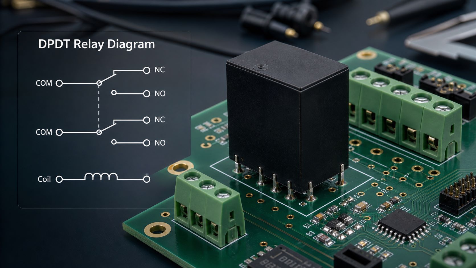
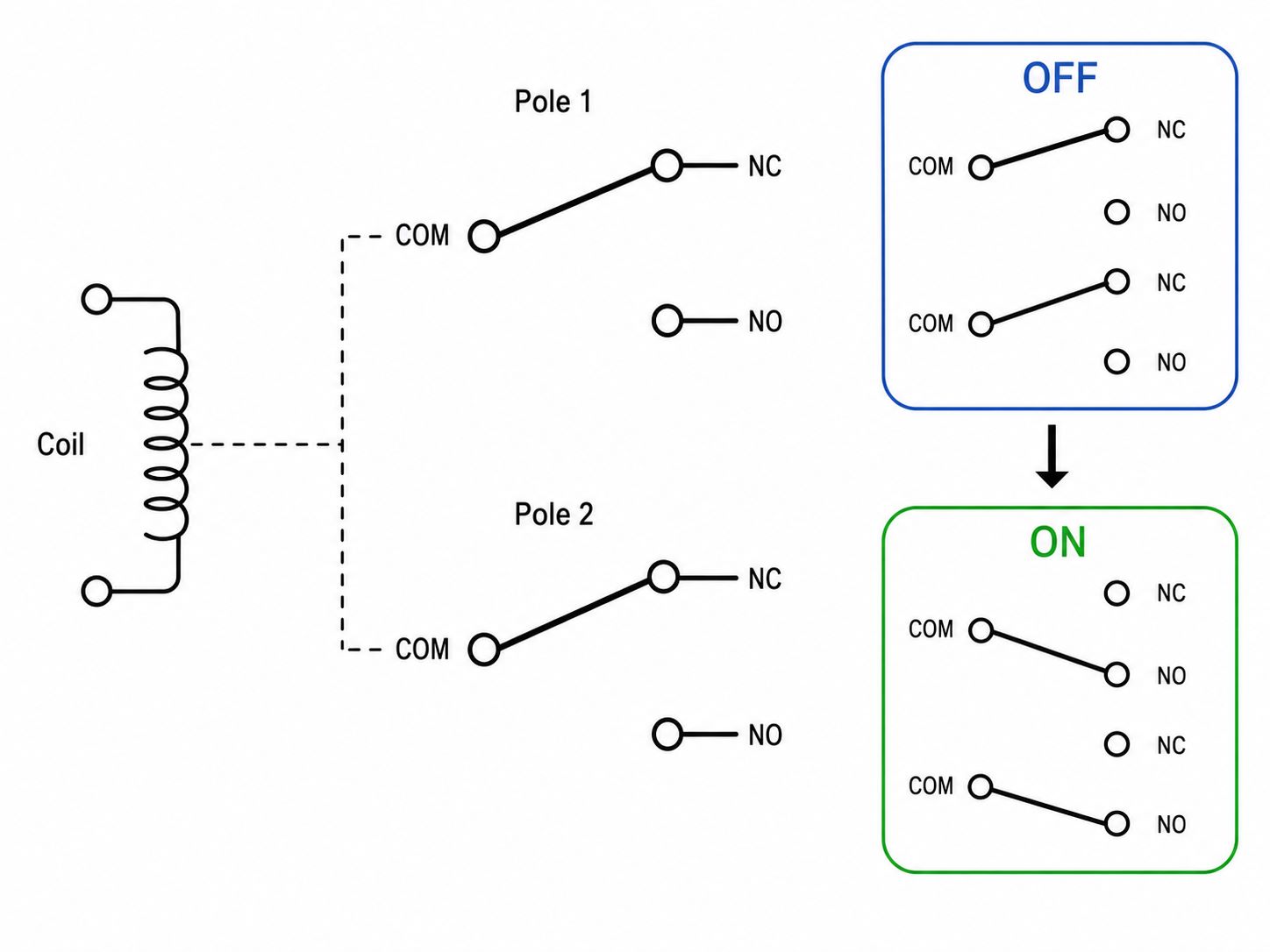
A DPDT relay means Double Pole Double Throw. “Double pole” means the relay controls two separate circuits. “Double throw” means each circuit can switch between two output paths.
A basic DPDT relay diagram usually includes:
| Part | Meaning |
|---|---|
| Coil | Electromagnetic control side |
| COM | Common terminal |
| NO | Normally open contact |
| NC | Normally closed contact |
| Pole 1 | First switching circuit |
| Pole 2 | Second switching circuit |
When the coil is not energized, each COM terminal usually connects to its NC terminal. When the coil is energized, each COM terminal switches to its NO terminal.
This is why a DPDT relay is often described as two SPDT switches controlled by one coil. But in real PCB design and PCBA production, you should still treat the relay as one physical component with one datasheet, one footprint, one coil rating, and one contact rating.
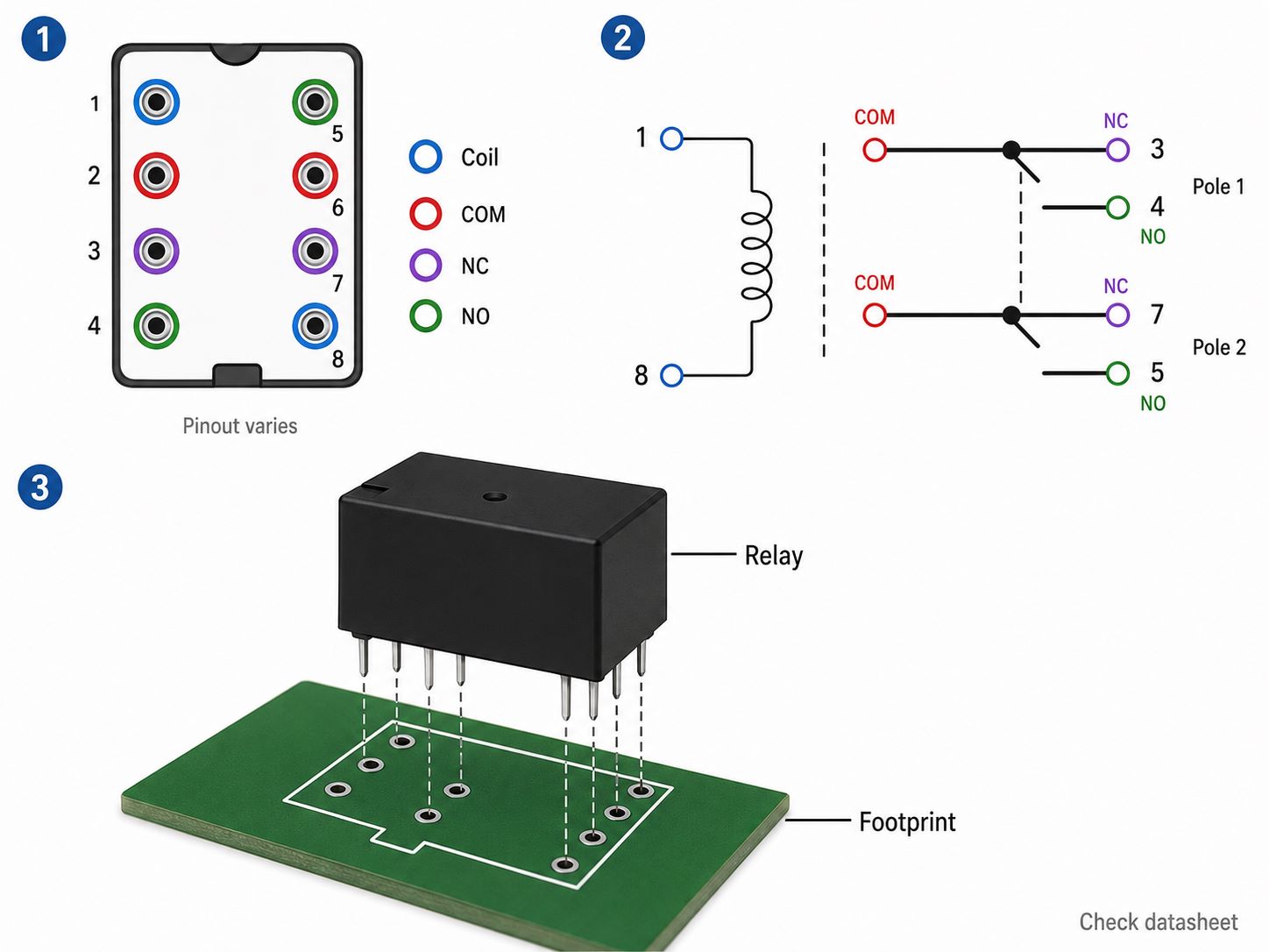
The most important rule is simple: do not rely on a generic DPDT relay diagram alone. Always check the relay datasheet and pinout. Different relay models may use different pin numbering and package layouts.
DPDT Relay Symbol and Pinout Explained
A DPDT relay symbol usually shows two switch sections and one coil. The coil controls both contact groups at the same time.
In many diagrams, you will see two groups like this:
- COM1, NO1, NC1
- COM2, NO2, NC2
- Coil A, Coil B
The symbol explains the electrical function. The pinout explains the physical terminal arrangement. These two are related, but they are not the same thing.
For PCB projects, this difference matters. A schematic symbol may look correct, but the PCB footprint may still be wrong if the pin mapping does not match the actual relay datasheet.
Before manufacturing, the engineering file should confirm:
- Coil pins
- Contact pins
- COM, NO, and NC mapping
- Pin pitch
- Relay body size
- Through-hole or surface-mount package
- Clearance between coil side and contact side
- Mechanical height and enclosure fit
A wrong relay pinout can cause a prototype to fail even when the circuit idea is correct.
8 Pin DPDT Relay Wiring Diagram
An 8 pin DPDT relay wiring diagram is common because many DPDT relays use 2 coil pins and 6 contact pins.
A typical 8 pin DPDT relay includes:
| Pin Group | Function |
|---|---|
| 2 pins | Coil |
| 2 pins | COM terminals |
| 2 pins | NO terminals |
| 2 pins | NC terminals |
However, the exact pin numbers depend on the relay model. Some relays place coil pins on one side. Some use a symmetrical layout. Some socket-mounted relays follow a different numbering system from PCB-mounted relays.
For PCB and PCBA work, the 8 pin diagram should be checked against:
- Relay datasheet
- PCB footprint
- Silkscreen marking
- Drill hole size
- Pad size
- Contact current requirement
- Relay socket requirement, if used
- Assembly orientation
If the board is already designed, EBest Circuit can help review whether the relay footprint, hole size, pad size, and assembly notes are clear enough for production. We do not change the circuit function without customer approval, but we can help catch manufacturability risks before the board is built.
DPDT Relay Wiring Diagram for DC Circuits
A DPDT relay wiring diagram for DC circuits is often used for polarity reversal or motor direction control. By crossing the contact connections correctly, the relay can reverse the polarity applied to a DC motor or load.
This is one reason the related keyword dc relay wiring diagram dpdt has strong search demand. Many users are trying to understand how a relay changes current direction.
For PCB projects, DC relay circuits need more than a correct diagram. The board should also consider:
- Load current
- Contact rating
- Coil voltage
- Coil drive transistor or MOSFET
- Flyback diode or suppression circuit
- Trace width for load current
- Copper thickness
- Heat rise
- Terminal block or connector rating
- Isolation between control and load circuits
If the relay drives an inductive load such as a motor, solenoid, or valve, suppression components may be needed to protect the driver circuit and reduce electrical noise. The exact circuit choice belongs to the customer’s design team, but the PCB manufacturer should check whether the layout, spacing, copper, and assembly files can support the requirement.
SPDT vs DPDT Relay Diagram Differences
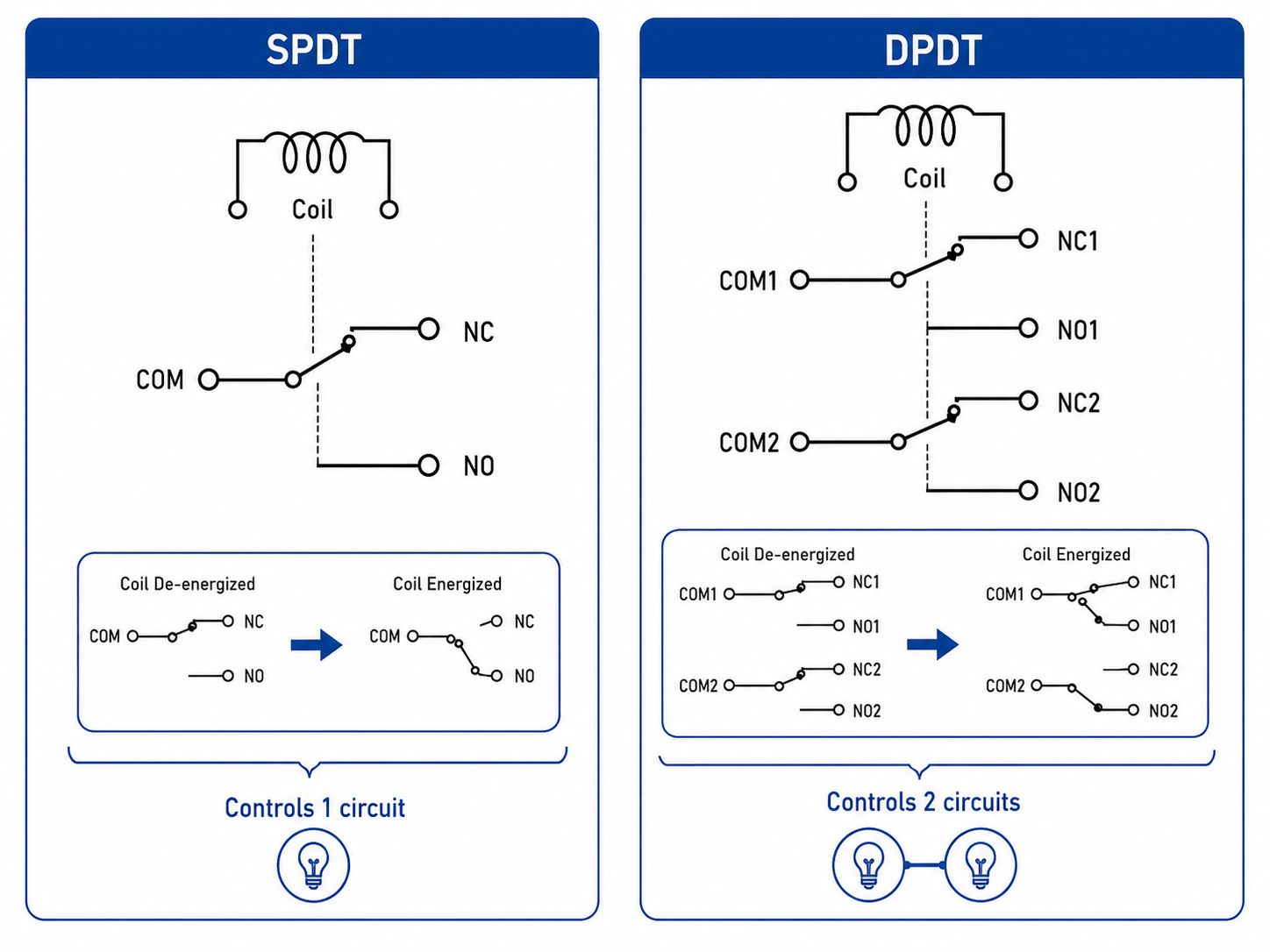
An SPDT relay, also called a single pole double throw relay, has one common terminal switching between one NO and one NC contact. A DPDT relay has two such switching groups controlled together. When reading the schematic, it also helps to recognize the switch SPDT symbol, because a DPDT relay diagram is essentially two SPDT-style switching sections controlled by one coil.
| Relay Type | Contact Structure | Typical Use |
|---|---|---|
| SPDT | 1 COM, 1 NO, 1 NC | One circuit changes state |
| DPDT | 2 COM, 2 NO, 2 NC | Two circuits switch together |
It is also important not to confuse DPDT with other pole-and-throw structures. For example, a single throw double pole switch PCB uses a different contact logic from a DPDT relay, because it switches two poles in only one throw position instead of switching each pole between two throws.
A DPDT relay is useful when two paths need to change at the same time. Examples include:
- Reversing DC motor polarity
- Switching two signal lines
- Selecting between two power paths
- Isolating two control channels
- Changing load connections in pairs
A DPDT relay is not automatically better than an SPDT relay. It is larger, may cost more, and may require more PCB space. If only one circuit needs switching, SPDT may be enough. If two circuits must switch together, DPDT becomes useful.
For PCB layout review, the practical question is not only “SPDT or DPDT?” It is whether the selected relay matches the circuit current, voltage, footprint, board space, and assembly method.
Double Pole Double Throw Relay Diagram Applications
A double pole double throw relay diagram is especially useful when the switching logic is easier to understand visually than through text.
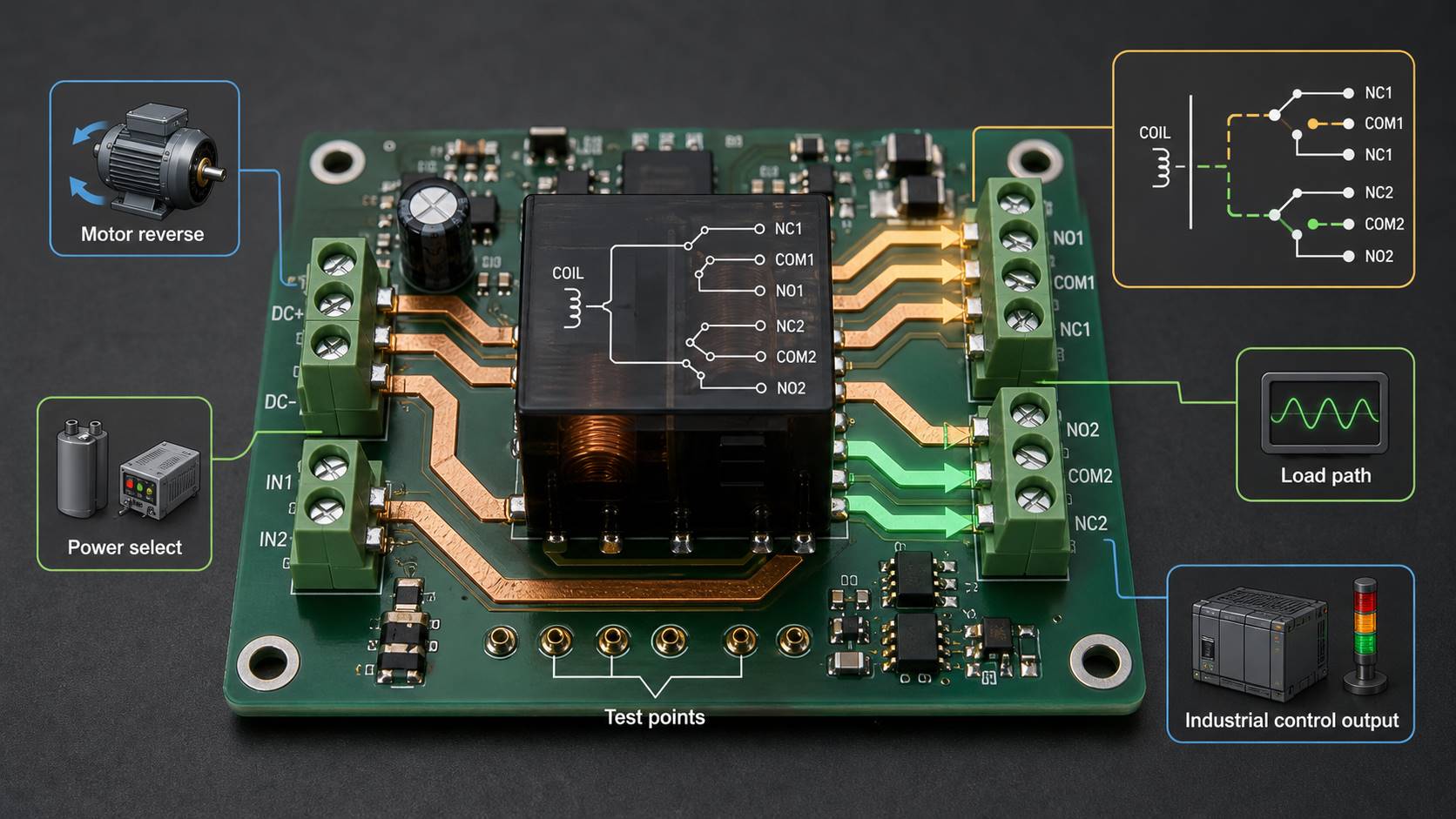
Common applications include:
- DC motor forward and reverse control
- Battery polarity switching
- Audio or signal path selection
- Industrial control modules
- Test equipment switching
- Automation relay boards
- Safety interlock circuits
- Power source selection
For PCBA projects, these applications often involve connectors, terminal blocks, high-current traces, mixed signal paths, or through-hole relay assembly.
Manufacturing review should pay attention to:
- Relay body clearance
- Connector location
- Terminal current rating
- Copper width for load paths
- Solder joint strength
- Mechanical stress during plugging and unplugging
- Board thickness and mounting method
- Test points for relay output verification
A relay circuit may look simple, but the assembled board must survive real switching, load current, heat, vibration, and repeated operation.
DPDT Relay PCB Layout Checks Before Manufacturing
For a DPDT relay board, PCB layout manufacturability should be reviewed before production starts.
Important checks include:
| Check Item | Why It Matters |
|---|---|
| Footprint | Prevents pin mismatch |
| Hole size | Supports through-hole insertion |
| Pad size | Affects solder joint strength |
| Trace width | Supports load current |
| Clearance | Reduces voltage risk |
| Copper thickness | Affects current and heat |
| Silkscreen | Helps assembly orientation |
| Test points | Supports inspection and testing |
If the relay switches a higher current load, copper thickness and trace width become important. If the relay switches higher voltage, creepage and clearance should be reviewed. If the relay is large or heavy, mechanical support and solder joint reliability should not be ignored.
EBest Circuit can review PCB manufacturing files, stackup, copper thickness, drill files, solder mask, and assembly notes before production. This helps reduce avoidable risks such as incorrect relay orientation, weak solder joints, insufficient copper width, and unclear assembly requirements.
DPDT Relay PCBA Assembly and Testing Notes
DPDT relays may be assembled by through-hole soldering, selective soldering, wave soldering, or manual soldering depending on the board design and production quantity.
For PCBA assembly, key points include:
- Relay orientation
- Through-hole insertion quality
- Solder filling
- Contact-side spacing
- Coil-side polarity, if applicable
- Connector and terminal block assembly
- Cleaning requirements
- Functional testing after assembly
A relay PCBA should not only be checked visually. Functional testing is often needed because the relay must switch correctly when the coil is energized.
Useful test checks may include:
- Coil activation
- COM to NC continuity before activation
- COM to NO continuity after activation
- Load path verification
- Connector output verification
- LED or indicator function, if included
- No short circuit between isolated paths
For prototype and small-batch production, this kind of test planning can help find assembly or wiring problems before the board is shipped.
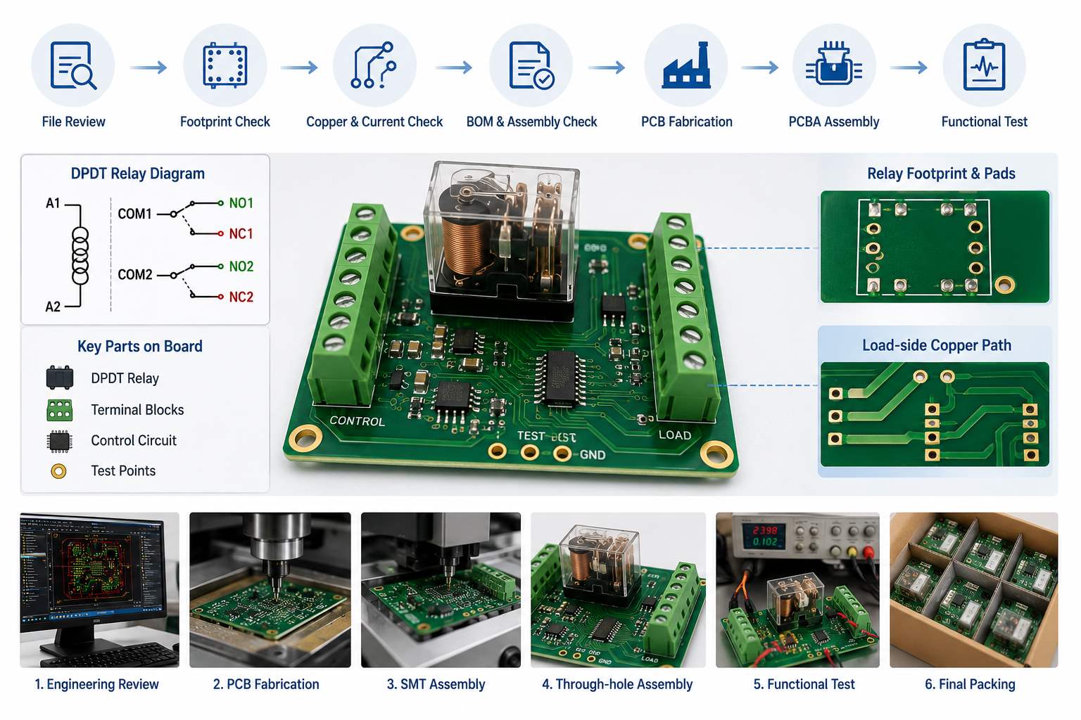
DPDT Relay PCB Project Case Study at EBest Circuit
A customer working on an industrial control module needed a relay-based PCB assembly for switching external loads. The project used relay output, connector terminals, and control-side components on the same PCBA, so the customer cared about both electrical function and assembly reliability.
The main challenge was not only placing a DPDT relay on the board. The board needed the relay footprint, terminal blocks, copper paths, and test points to match the customer’s switching logic.
Project focus
- Relay control circuit
- Through-hole relay assembly
- Terminal block connection
- Load-side copper review
- Control-side SMT components
- Functional test after assembly
- Production file confirmation before build
EBest Circuit’s review
- Checked relay footprint and drill requirements
- Reviewed pad size and soldering feasibility
- Confirmed connector and relay orientation notes
- Reviewed copper paths for load-side current
- Checked BOM and assembly files before SMT
- Coordinated PCB fabrication and PCBA assembly together
- Supported functional test planning based on customer requirements
This type of project shows why a DPDT relay diagram should not stay only at the schematic level. Once the design moves to a real PCB, the relay becomes a physical assembly item with footprint, soldering, spacing, copper, connector, and test requirements.
For engineers, the value of one-stop PCB and PCBA support is that these details stay visible from file review to final delivery.
FAQs about DPDT Relay Diagram
1. What does DPDT mean in a relay diagram?
DPDT means Double Pole Double Throw. It has two switching sections, and each section can switch one common terminal between normally open and normally closed contacts.
2. How many pins does a DPDT relay have?
Many DPDT relays have 8 pins: 2 coil pins and 6 contact pins. However, the exact pinout depends on the relay model, so the datasheet must be checked.
3. What is the difference between SPDT and DPDT relay diagrams?
An SPDT relay switches one circuit. A DPDT relay switches two circuits at the same time. DPDT is useful when two paths need to change together.
4. Can a DPDT relay reverse motor direction?
Yes, a DPDT relay can be wired to reverse DC motor polarity. The exact circuit should be reviewed carefully, especially for current rating, suppression, and trace width.
5. Why does a DPDT relay diagram matter for PCB manufacturing?
The diagram helps explain the switching logic, but PCB manufacturing also needs the correct footprint, pinout, hole size, pad size, clearance, copper width, and assembly orientation.
If your project includes relays, terminal blocks, load switching, control circuits, or assembled relay PCBA, please contact sales@bestpcbs.com. EBest Circuit can help review PCB files, BOM, assembly notes, and production requirements before your relay board enters manufacturing.