





An SMB connector gives an RF design a compact, snap-on connection. Choosing the right version means matching the mating interface, system impedance, cable, and mounting arrangement. A connector that fits physically can still create an electrical mismatch or put unnecessary strain on the PCB.
EBest Circuit (Best Technology) combines PCB fabrication, component sourcing, and PCB assembly, including SMT and through-hole processes. This supports RF boards that need both a suitable connector footprint and a practical assembly process. Contact sales@bestpcbs.com to discuss your board and connector requirements.
What Is an SMB Connector?
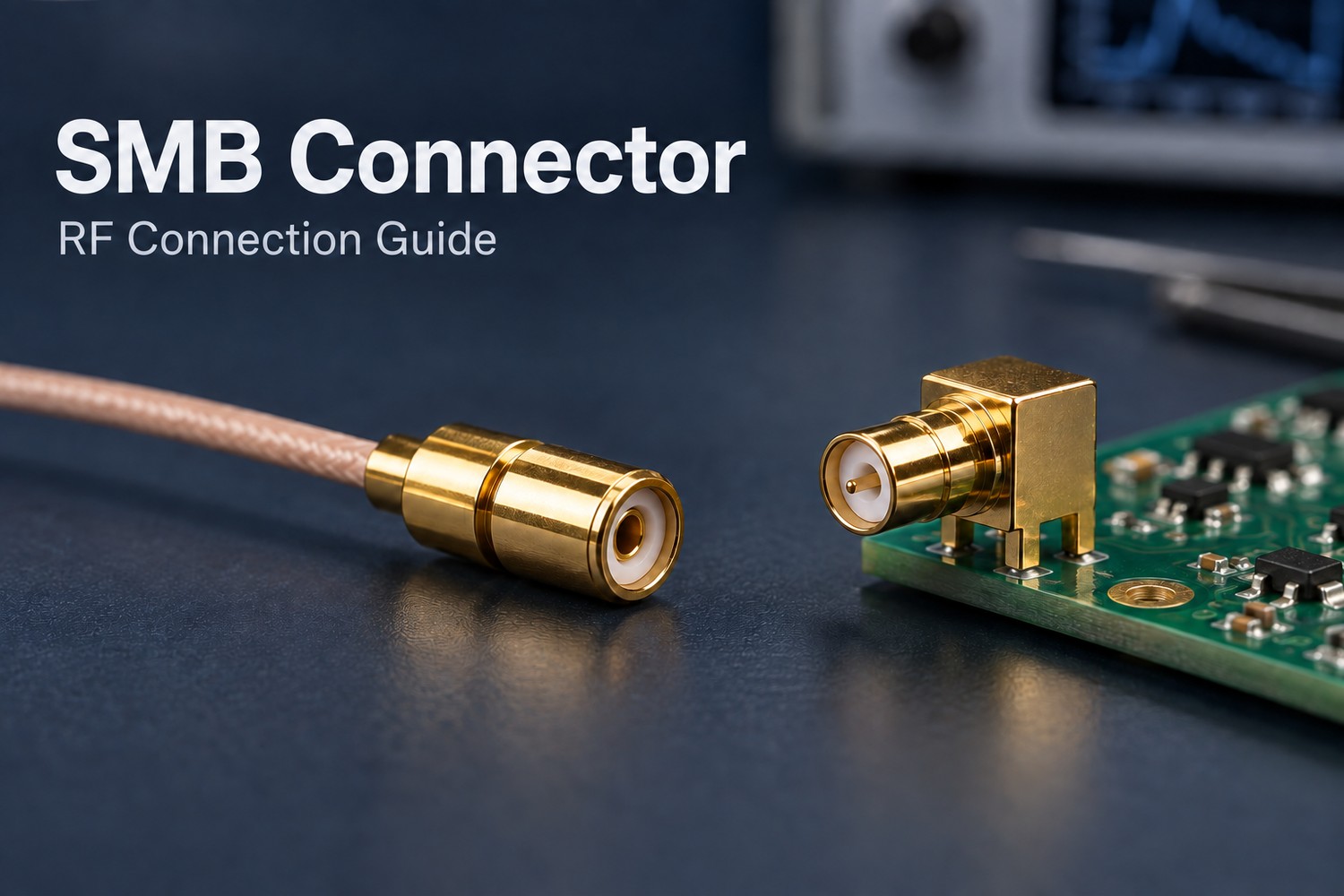
An SMB connector, short for SubMiniature B, is a coaxial RF connector with snap-on coupling. It connects by pushing the mating halves together, without tightening a threaded nut.
Its coaxial structure has three main elements:
- Center contact: carries the signal.
- Dielectric: separates the conductors and helps establish impedance.
- Outer conductor: provides the return path and shielding.
SMB is useful for compact internal RF links in communications equipment and instruments. Available versions include 50-ohm and 75-ohm interfaces, cable terminations, and PCB mounts; the family name alone does not specify their frequency rating.
How Do You Identify an SMB Plug and an SMB Jack?
In common standard SMB interfaces, the plug has a center socket and the jack has a center pin. This is easy to misread if you normally associate “plug” with a male pin.
| SMB interface | Center contact | Mates with |
|---|---|---|
| Plug | Female socket | Compatible SMB jack |
| Jack | Male pin | Compatible SMB plug |
Catalog labels such as “male” and “female” may describe the contact rather than the complete interface. Use the manufacturer’s mating drawing to resolve ambiguous descriptions.
Also keep interface gender and mounting style separate: a PCB mount is not a gender designation. For a replacement, match the interface first, then the impedance, footprint, and orientation.
How Do 50-Ohm and 75-Ohm SMB Connectors Differ?
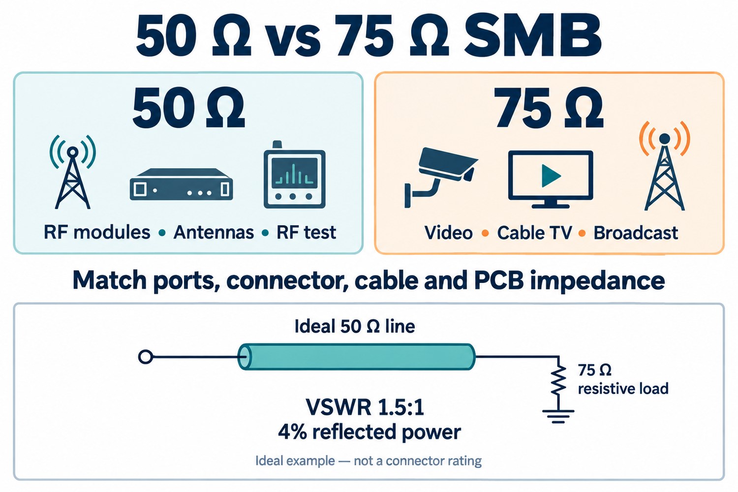
50-ohm and 75-ohm SMB connectors match different transmission-system impedances. The same distinction appears across several coaxial connector families:
| Impedance | Common connector examples | Typical applications |
|---|---|---|
| 50 ohms | SMA; 50-ohm BNC, N-Type, and SMB | Antenna feeds, wireless modules, RF test equipment |
| 75 ohms | F-Type; 75-ohm BNC and SMB | Cable television, video transmission, broadcast equipment |
For SMB, conductor dimensions and dielectric geometry establish the impedance. Select the version that matches the equipment ports, coaxial cable, and PCB transmission line. Physical mating does not establish electrical compatibility.
A mismatch creates reflections and can raise VSWR. For example, an ideal 50-ohm line feeding a purely resistive 75-ohm load has a VSWR of 1.5:1, with 4% of incident power reflected. This illustrates the mismatch; it is not a universal rating for a 75-ohm SMB inserted into a 50-ohm assembly.
Actual results depend on frequency, connector transitions, cable length, and the PCB launch. Reflections can cause response ripple and reduce signal margin. Compare VSWR or return loss across the operating band: lower VSWR and higher return loss indicate a better match. Neither impedance is inherently superior.
SMA vs SMB Connector: Which Fits Your RF Connection?
SMB favors quick snap-on access; SMA provides a threaded connection. Choose around the required retention, service access, and operating frequency.
| Design requirement | SMB | SMA |
|---|---|---|
| Connection method | Push to engage; pull the body to release | Threaded coupling nut, tightened to specified torque |
| Installation clearance | Room for axial movement and a secure grip | Room to turn the nut and use the required tool |
| Common fit | Compact internal connections needing quick access | RF connections where threaded retention is preferred |
Frequency capability belongs to the specific part. For example, Samtec lists SMB offerings with 50-ohm performance to 6 GHz and 75-ohm performance to 4 GHz. These figures do not apply to every SMB connector.
For vibration or moving cables, assess the connector’s retention specification and cable support. A coupling style alone does not establish environmental suitability.
Which SMB Cable Connector Fits Your Coaxial Cable?
Choose a connector approved for the exact cable construction, not just its impedance. RG316 is a common 50-ohm example; RG179 is used in 75-ohm assemblies. Their connector terminations are not automatically interchangeable.
Three details determine the fit:
- Cable dimensions: the center conductor, dielectric, shield, and jacket must fit the contact and termination hardware.
- Termination method: “crimp” may mean a crimped outer ferrule with a soldered center contact. Follow the specified stripping dimensions and tooling.
- Cable exit: a right-angle body can reduce installed height; a straight body needs room for the cable’s bend radius.
Provide strain relief so cable pull is carried by the support structure rather than the termination or PCB solder joints.
When Should You Choose a Board-Mount or Panel-Mount SMB Connector?
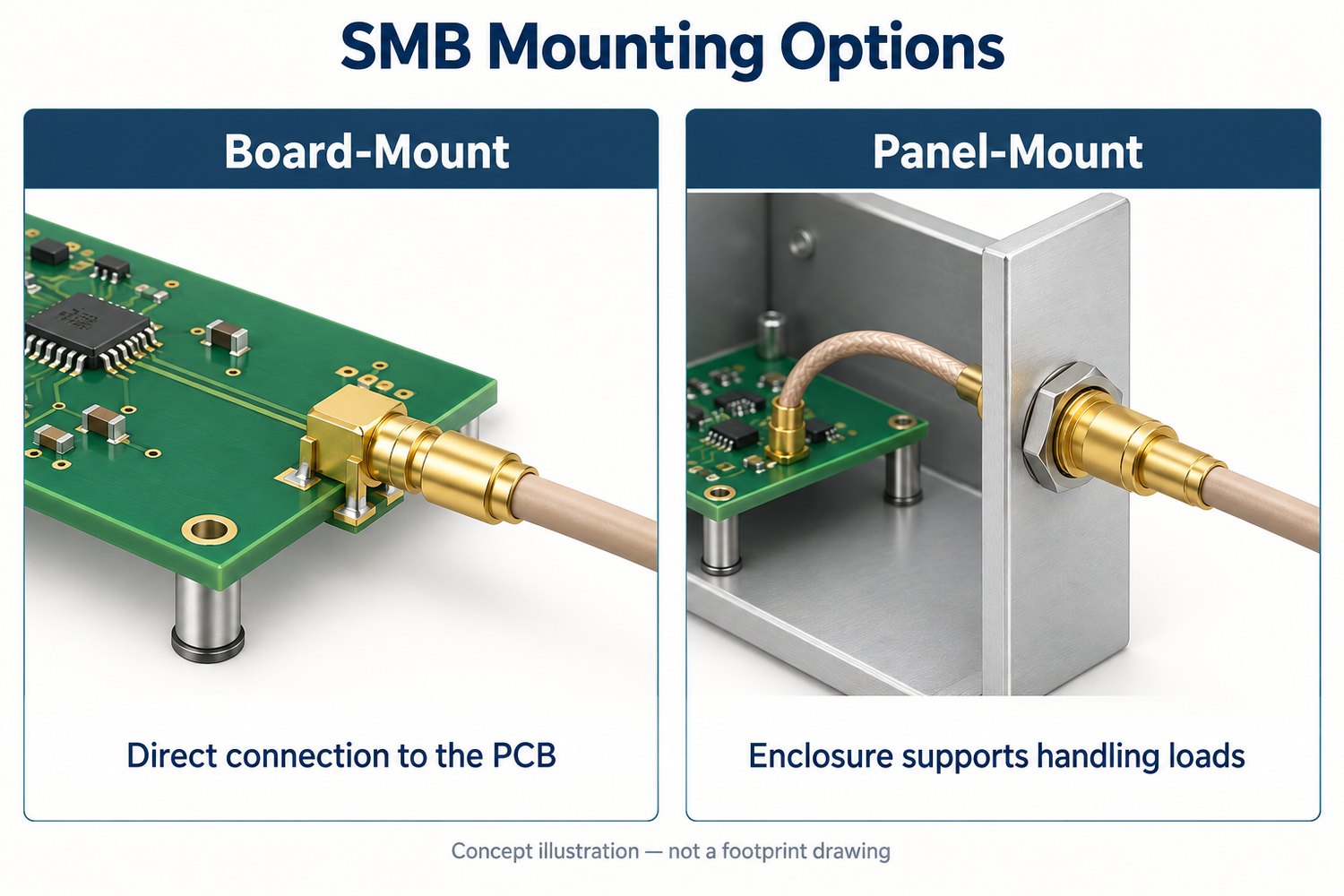
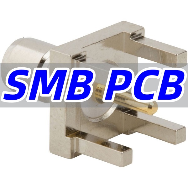
Use board mounting for a direct PCB connection and panel mounting when the enclosure should support the accessible interface. Some connectors combine PCB termination with bulkhead mounting.
- Board-mount: suits a direct cable-to-board RF path. The manufacturer’s footprint, ground connections, and signal transition matter because the connector-to-trace junction is part of the RF circuit.
- Panel-mount: suits an externally accessed port. A properly supported bulkhead transfers plugging and cable-handling forces into the enclosure.
Check the assembled geometry: board-to-panel distance, panel thickness, connector orientation, and finger clearance. Compatible SMB mating faces do not guarantee identical PCB footprints.
For the board-side details, see our guide to SMB PCB fabrication and assembly.
How Do You Connect and Disconnect an SMB Connector?
Push and pull along the mating axis while holding the connector body. Standard snap-on SMB interfaces do not screw together like SMA.
- Inspect: look for debris, bent contacts, or shell damage. Follow the equipment’s RF power-down instructions.
- Align: bring both halves onto the same axis before applying pressure.
- Seat: push steadily until fully engaged. Stop if resistance feels abnormal.
- Release: support the fixed connector and pull the mating body straight back.
Do not pull on the cable or lever the connector against the PCB. Where access is restricted, provide more clearance or use a manufacturer-approved removal tool.
FAQs About SMB Connectors
Are SMB, Mini-SMB, and SSMB interchangeable?
No interchangeability should be assumed. They are separately specified interface families; similar names and snap-on coupling do not guarantee matching dimensions. Use the manufacturer’s mating information.
Are SMB connectors waterproof?
Not by designation. An exposed connection needs an explicit protection rating covering the connector, termination, and intended assembled condition.
Does an SMB-to-SMA adapter match 75 ohms to 50 ohms?
A basic interface adapter does not automatically transform impedance. If the circuit requires impedance matching, use an appropriate matching device or network.
Does the connector rating establish the cable assembly’s frequency performance?
No. Cable length and loss, both connectors, and terminations affect the finished assembly. Use assembly-level insertion-loss and return-loss specifications for the operating band.
What causes a loose SMB connection?
Possible causes include incomplete engagement, incompatible mating parts, worn retention features, or a loose mount. Identify the cause and replace damaged parts; do not squeeze the shell or bend contacts to tighten the fit.
Planning an RF board with an SMB connector? Send your PCB files, BOM with the connector part number, and required quantity to sales@bestpcbs.com. EBest Circuit can support fabrication, sourcing, and assembly around your selected components.
You may also like



Tags: PCB Assembly, RF Connectors, SMB Connector
