This article provides a clear definition for open circuit, analyzes its effects, and explains how to identify and prevent it in PCB manufacturing and everyday electronics. An Open Circuit is defined as a break or interruption in an electrical path that prevents current from flowing.
When an electrical device fails, the culprit is often a break in the conductive path. For engineers and procurement managers, these failures translate into delays, costs, and reputational damage. Have you ever faced these frustrating scenarios?
- Unexpected Device Failure: A fully assembled product is dead on arrival during final testing.
- Intermittent Faults: A device works intermittently, leading to unreliable performance and difficult debugging.
- Costly Rework: Identifying the exact location of a break in a complex, multi-layer PCB requires expensive equipment and skilled labor.
- Production Delays: Faulty batches halt assembly lines, pushing back delivery schedules and disappointing clients.
- Field Returns and Warranty Claims: Latent open circuit defects that escape factory testing result in customer returns, harming your brand.
These issues underscore the critical need for robust design, manufacturing, and testing processes. The solution lies in partnering with a manufacturer that prioritizes prevention and precision at every step.
- Prevention-First Design: Implementing DFM (Design for Manufacturing) checks to eliminate thin trace designs and thermal stress points prone to cracking.
- Advanced Process Control: Utilizing automated optical inspection (AOI) and controlled lamination processes to prevent micro-cracks and plating voids.
- Comprehensive Electrical Testing: Employing 100% electrical test (E-test) and flying probe testing to verify the continuity of every net on the PCB.
- Accelerated Life Testing: Subjecting boards to thermal cycling and stress tests to identify weak points before they reach your assembly line.
- Expert Engineering Support: Providing direct access to FA (Failure Analysis) engineers who can quickly diagnose root causes and implement corrective actions.
At EBest Circuit (Best Technology), we are a professional PCB and PCBA manufacturer focused on delivering zero-defect reliability. Our engineering team specializes in designing and building robust circuits, implementing stringent quality control, and offering expert PCB fault analysis and engineering support to ensure your products are free from open circuits and other common failures. For a reliable partnership, pls feel free to contact us at sales@bestpcbs.com.
What Is the Definition for Open Circuit?
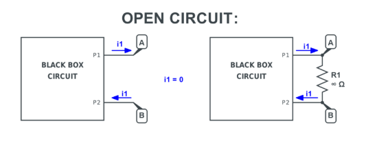
In electrical and electronic engineering, the definition for open circuit is fundamental. It describes an incomplete path in a circuit where the conductive continuity is broken. This break acts as an infinite resistance, stopping the flow of electric current entirely, much like a switch in the “OFF” position. Understanding this is crucial for both basic electronics and complex PCB manufacturing, as it is a primary failure mode that engineers must design against and test for.
- Core Concept: An interruption in a conductive path.
- Electrical Behavior: Infinite resistance, zero current flow (I=0).
- Voltage State: The full voltage of the source appears across the open point (per Ohm’s Law, V=IR).
- Analogy: A water pipe that has been pinched shut or severed.
- In Circuit Theory: Represented as a switch that is open.
In summary, an open circuit is not a designed state but a fault condition that disrupts the intended function of any electrical device, making its prevention and detection a top priority in quality control.
How Does an Open Circuit Affect a Simple Electrical Circuit?
In a simple circuit—comprising a power source, conductive wires, and a load like a lamp—an open circuit completely halts operation. The break, which could be a severed wire or a loose connection, creates a gap that current cannot cross. According to Ohm’s Law (V = IR), if the resistance (R) becomes infinitely high, the current (I) must drop to zero. Consequently, the load receives no power and ceases to function.
- Current Flow Stops: The primary and most direct effect is that no current flows through the circuit.
- Load De-energizes: Without current, the load (e.g., bulb, motor, resistor) does not operate, produce light, or generate heat.
- Voltage Distribution Shifts: The voltage from the power source appears entirely across the open point, while the voltage across the load drops to zero.
- No Power Dissipation: Since power (P = I²R) depends on current, the load dissipates no power.
- Safe but Non-Functional: While often safe from overheating (no current means no heat generation from the load), the circuit is rendered useless.
Therefore, in any simple circuit, an open circuit is synonymous with total failure. This foundational understanding scales directly to the far more complex networks found on printed circuit boards.
What Happens When a Circuit Becomes Open?
When an active circuit transitions from closed to open, an immediate and definitive sequence of electrical events occurs. The moment the path breaks—whether from physical stress, corrosion, or a failed component—the previously flowing current collapses to zero. This sudden change can have secondary effects, especially in circuits with inductive elements like motors or coils, which can generate high voltage spikes.
- Instantaneous Current Cessation: The flow of electrons stops abruptly at the break point.
- Full Source Voltage at the Break: The voltage potential difference appears across the two ends of the open, which can sometimes lead to arcing in high-voltage scenarios.
- Load Shutdown: All downstream components from the open point lose their operating power and stop functioning.
- Potential for Voltage Spikes: In inductive loads, the rapid change in current (dI/dt) can induce a high reverse voltage (V = -L * dI/dt), potentially damaging other components.
- Transition to a High-Impedance State: The circuit node on the powered side of the open becomes “floating” and can be susceptible to external electrical noise.
This transition is a critical fault scenario in PCB and PCBA quality control, as it represents a hard failure that must be caught before the board leaves the factory.
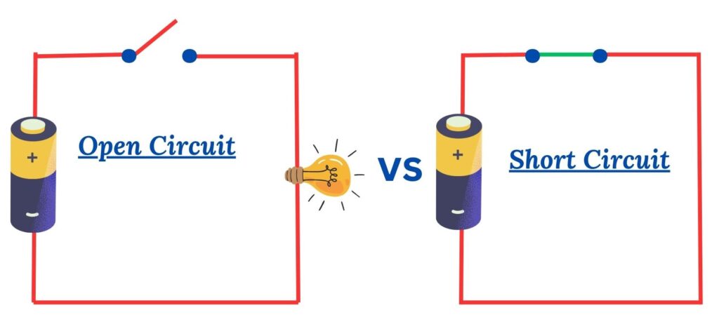
What Is the Difference Between an Open Circuit and a Closed Circuit?
Understanding electronics requires mastering the distinction between an open circuit and a closed circuit. They are two fundamental states that define whether a circuit is operational or not. The core difference lies in the continuity of the conductive path.
| Feature | Open Circuit | Closed Circuit |
|---|---|---|
| Path Continuity | Broken / Interrupted | Complete / Unbroken |
| Current Flow (I) | Zero (I = 0) | Flowing (I = V/R) |
| Resistance at Break | Ideally Infinite | N/A (No intentional break) |
| Circuit Function | Non-operational / Fault | Operational / Normal |
| Common Analogy | A light switch in the OFF position | A light switch in the ON position |
| Voltage Across Load | 0V (No current flow) | Varies per Ohm’s Law |
| Primary Cause | Fault (crack, bad solder, failed component) | Design Intent |
In essence, a closed circuit is the desired, functional state, while an open circuit represents a failure mode. Effective design and testing aim to ensure circuits remain reliably closed during their operational life.
What Are Common Examples of Open Circuits in Daily Life?
Open circuits are not just abstract concepts; they are behind many everyday electrical failures. Recognizing these examples helps in troubleshooting simple devices. Here are some common examples of open circuits in daily life:
- Blown Fuse: The thin metal strip inside a fuse melts (opens) to break the circuit and prevent damage from overcurrent, creating a deliberate open circuit for safety.
- Burnt-Out Light Bulb: The filament inside an incandescent bulb breaks due to overheating and age, creating an open circuit that stops current flow.
- Tripped Circuit Breaker: A safety device that mechanically opens (trips) the circuit in your home’s electrical panel during an overload or short circuit.
- Severed Power Cord: Physical damage to a wire, like from a vacuum cleaner running over a cord, can cut the internal conductors, creating an open.
- Loose Battery Contact in a Remote: Corrosion or a weak spring can break the electrical connection between the battery and the device terminals.
- Faulty Wall Switch: A broken or worn-out light switch internally fails to connect the contacts, leaving the circuit open even when flipped “on.”
These failures highlight the practical importance of maintaining a closed, low-resistance path for electricity to flow as intended.
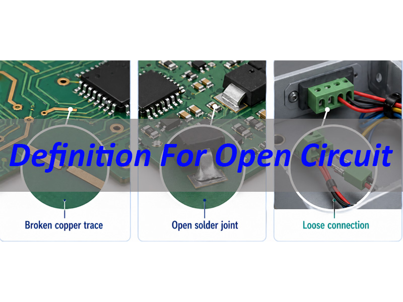
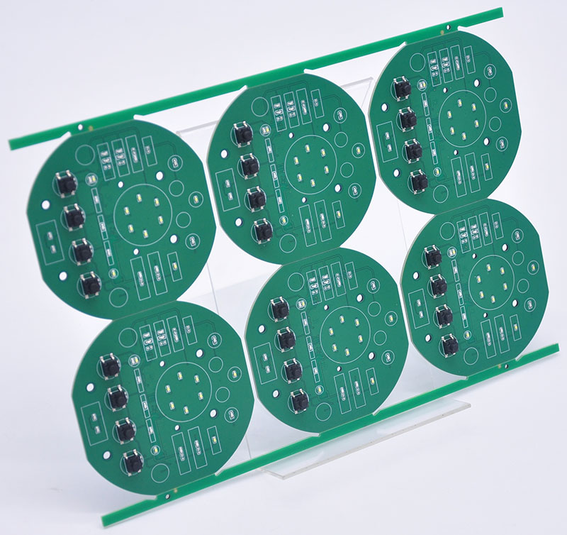
What Does an Open Circuit Mean in PCB Manufacturing?
In the context of PCB manufacturing, an open circuit refers specifically to a break in a designed conductive trace, via, or pad that prevents electrical connection between two points on the board. This is a critical defect that can render a PCB assembly (PCBA) completely non-functional. It is a primary target for detection during electrical testing. Opens can occur due to various process issues:
- Trace Cracks: From mechanical stress during depaneling or flexing, or due to thermal cycling stress.
- Plating Voids in Vias: Incomplete copper deposition inside a via barrel during the plating process, creating a discontinuity between layers.
- Poor Etching: Over-etching can cause “mouse bites” or sever thin traces, while under-etching can cause shorts, not opens.
- Lifted Pads: Excessive mechanical or thermal stress (e.g., during rework) can cause a pad to separate from the substrate, breaking connections to its trace.
- Solder Mask Over Trace: Incorrect solder mask application can cover a pad or a thin trace section, preventing solder wetting and electrical connection during assembly.
Preventing these defects requires meticulous process control, which is central to our PCB fault analysis and engineering support at EBest Circuit.
Why Is Open Circuit Testing Important in PCB and PCBA Quality Control?
Open circuit testing is a non-negotiable pillar of PCB and PCBA quality control. Its importance cannot be overstated, as it directly correlates to first-pass yield, functional reliability, and overall product cost. Testing verifies the physical integrity of the manufactured board against its designed netlist.
- Ensures Basic Functionality: Catches catastrophic faults that would 100% cause a board to fail.
- Prevents Costly Rework Downstream: Finding an open on a bare PCB is far cheaper than after expensive components are soldered on in PCBA.
- Validates Manufacturing Process: Serves as a key metric for process health (e.g., plating, etching, lamination).
- Reduces Field Failure Rates: Boards that pass electrical testing are exponentially more reliable in the end product, reducing warranty claims.
- Supports Complex Assemblies: In high-density interconnect (HDI) or multi-layer boards, visual inspection is insufficient; electrical testing is the only sure verification.
Without comprehensive open and short circuit testing, manufacturers ship boards with a high probability of failure, passing immense risk and cost onto their customers.
How Can You Identify an Open Circuit in a PCB or Electrical Device?
Identifying an open circuit requires a systematic approach, moving from simple checks to sophisticated tools. Here is a standard troubleshooting methodology:
- Visual Inspection: Use a magnifier or microscope to look for obvious signs like cracked traces, damaged vias, or poor solder joints (cold solder joints can be opens).
- Continuity Test with a Multimeter: The most common method. Set a digital multimeter (DMM) to continuity or resistance mode (beep mode). Place probes on both ends of the suspected trace/connection. No beep or infinite resistance (OL) indicates an open.
- Voltage Tracing: Power the circuit. Use the DMM in voltage mode. Start from the power source and follow the intended path, measuring voltage at successive points. A point where voltage is present but the next point in line is 0V (with respect to ground) is likely just after an open.
- Advanced Tools:
- Flying Probe Tester: Used in manufacturing to automatically test continuity on every net of a bare or assembled PCB.
- Time Domain Reflectometry (TDR): Sends a signal pulse down a trace; the reflection from an open (or other impedance discontinuity) helps locate the fault with pinpoint accuracy, even on inner layers.
For complex failures, leveraging a manufacturer’s engineering support team, like ours at EBest Circuit, with access to these advanced tools is the most efficient path to resolution.
To sum up, an Open Circuit is defined as a break in an electrical path that halts current flow, representing a fundamental failure mode in any electronic system. This article has provided a clear definition for open circuit, explored its effects, differences, and real-world examples, and emphasized its critical importance in PCB manufacturing and quality control.
Preventing and detecting opens requires expertise at every stage, from design to final test. EBest Circuit (Best Technology) specializes in this exact discipline. We combine rigorous process control, 100% electrical testing, and deep engineering analysis to deliver PCBs and assemblies with exceptional reliability, minimizing the risk of open circuits in your products. For boards you can trust, pls feel free to contact our team at any time at sales@bestpcbs.com.
FAQs About Definition For Open Circuit
Q: Can an open circuit be dangerous?
A: While generally safer than a short circuit (which causes high current and heat), an open circuit can be dangerous in certain contexts. The voltage present across the open gap can cause arcing in high-voltage systems, posing a fire or shock risk. Also, an open circuit in a safety-critical system (e.g., a brake sensor) creates a functional failure hazard.
Q: Is an open circuit the same as a high resistance connection?
A: Not exactly, but it is on the same spectrum. A perfect open has infinite resistance. In practice, a severely corroded or cracked connection may have a very high but not infinite resistance (e.g., several megaohms). This can cause intermittent operation, voltage drops, and heat generation, and is often called a “high-resistance open” or a “partial open.”
Q: How can I prevent open circuits in my PCB design?
A: Follow DFM guidelines: avoid overly thin traces, use tear drops for trace-to-pad connections, follow appropriate annular ring sizes for vias, and consider the board’s mechanical stress points. Partnering with an experienced manufacturer early in the design phase is the best prevention.
Q: What’s the difference between an ‘open’ and a ‘short’ on a PCB?
A: They are opposite failure modes. An Open Circuit is a breakwhere there should be a connection (high resistance). A Short Circuit is an unintended connectionbetween two nets that should be separate (very low resistance). Both are critical defects tested for in PCB manufacturing.