





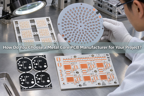
A capable metal core PCB manufacturer must do more than place copper over an aluminum plate. The manufacturer must match the metal core, dielectric, copper weight, circuit structure, mechanical dimensions, surface finish and inspection plan to the heat load and assembly method. At EBest Circuit (Best Technology), we manufacture custom metal core PCB prototypes and production boards in single-layer, two-layer, double-sided and multilayer constructions, subject to stackup and engineering review.
What Does a Metal Core PCB Manufacturer Build?
A metal core printed circuit board uses a metal layer as part of the board structure. The metal spreads heat away from power devices and can also add mechanical stiffness. Depending on the industry, the same family may be called an MCPCB, metal backed PCB, metal base PCB, insulated metal substrate PCB or metal clad PCB. These names overlap, but the drawing still needs to identify the actual layer sequence and material requirements.
Our metal core PCB manufacturing work includes aluminum, copper, steel and stainless-steel core options. We review the electrical circuit, thermal path, dielectric isolation, finished thickness, outline and assembly interface together. A metal plate alone does not define an MCPCB; the finished board must place the circuit and insulation around that metal in a controlled stackup.
| Term used on an RFQ | What we confirm on the drawing | Typical manufacturing question |
|---|---|---|
| MCPCB / metal core PCB | Core material, dielectric and circuit-layer sequence | Where must heat enter the metal core? |
| Metal backed PCB / metal base PCB | Whether the metal is an integral base or a separate heatsink | Which surface interfaces with the housing? |
| Metal clad PCB | Copper-clad dielectric construction and metal-core location | Which copper weights and finishes are required? |
| Thermal substrates – MCPCB | Thermal conductivity, dielectric thickness and isolation requirement | What total thermal path must the board support? |
How Does an MCPCB Move Heat?
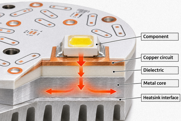
Heat normally moves from the component pad into the copper circuit, through the dielectric and into the metal core. The metal then spreads the heat toward a mounting surface, housing or external heatsink. The narrow dielectric layer is electrically necessary, but it is often a significant part of the through-thickness thermal resistance. Its conductivity and thickness must therefore be considered together.
A higher thermal-conductivity label does not by itself prove that the assembled product will run cooler. Pad area, copper coverage, component attachment, interface material, mounting pressure and the external cooling path all matter. We use the customer’s power map, component locations and mechanical interface to review whether a conventional MCPCB stackup is appropriate or whether another thermal structure should be considered.
Which Metal Core PCB Structures Can We Manufacture?
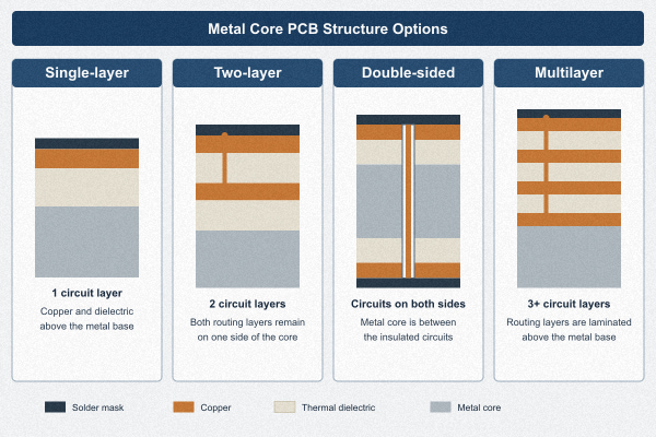
Structure selection starts with circuit routing and heat-flow needs. We manufacture simple one-circuit-layer boards as well as constructions that place more circuitry on one or both sides of the metal core. Each additional layer changes drilling, lamination, isolation and inspection requirements, so the final capability depends on the complete build rather than one isolated maximum.
- Single-layer MCPCB: one copper circuit layer over dielectric and a metal base.
- Two-layer MCPCB: two copper circuit layers placed on the same side of the metal core.
- Double-sided MCPCB: circuitry on both sides, with the metal core within the board structure.
- Multilayer MCPCB: more than two circuit layers combined with a metal-core thermal structure.
Which Metal Core Materials Fit the Application?
Aluminum is widely used because it combines useful heat spreading, low weight, availability and cost control. A copper core can provide higher bulk thermal conductivity and different current-spreading options, but it is heavier and normally more expensive. Steel and stainless-steel cores may be selected when stiffness, magnetic behavior, corrosion environment or mechanical integration matters more than maximum heat spreading.
The dielectric is just as important as the metal. We need its thickness, thermal conductivity, breakdown requirement and intended operating conditions. A metal core PCB material callout that names only “aluminum” leaves the insulation system undefined. For a copper core PCB or aluminum core PCB, send the approved material family or the electrical and thermal requirements that the material must meet.
What Are Our Detailed MCPCB Manufacturing Parameters?
The following values describe our advertised MCPCB capability envelope. They are useful for early feasibility screening, but several individual limits cannot automatically be combined in one build. Board shape, layer count, copper weight, metal type, dielectric system, hole structure, panel utilization and order quantity must be reviewed together before production release.
| Manufacturing item | Advertised capability | What must be confirmed for the project |
|---|---|---|
| MCPCB constructions | Single-layer, two-layer, double-sided and multilayer; up to 10 layers | Complete stackup, via isolation and metal-core location |
| Finished board thickness | 0.30–4.0 mm | Core thickness, dielectric, copper and finished tolerance |
| Maximum listed format | 100 × 1,300 mm | Outline, panel direction, warpage and equipment fit |
| Minimum line / space | 0.15 / 0.15 mm | Copper weight, etch compensation and local pattern density |
| Minimum finished hole | 0.30 mm | Hole type, aspect ratio, isolation and plating requirement |
| Maximum listed aspect ratio | 12:1 | Board thickness, hole diameter and actual hole construction |
| Thermal-conductivity options | 0.8–1.0, 1.5, 2.0 and 3.0 W/m·K listed | Material family, test method, dielectric thickness and isolation |
| Production stage | Prototype, small batch and volume production | Quantity, panelization, qualification and repeat-order controls |
Single-Sided Metal Core PCB Manufacturing
A single-layer structure is often the most direct choice when all components and conductors can remain on one side. As a single sided metal core PCB manufacturer, we check the component-side copper, dielectric, metal-base thickness, mounting-hole insulation, outline and flatness together. The board may be simple in layer count, but thermal and mechanical requirements can still make the build application-specific.
Single-layer MCPCBs are common in lighting, power conversion and compact thermal assemblies. Before quoting, we need to know whether the metal back will contact a heatsink, whether mounting hardware needs electrical isolation, and whether the assembly process requires a particular solder-mask color, surface finish or panel format.
Two-Layer and Double-Sided MCPCB Manufacturing
A two-layer MCPCB places two circuit layers on the same side of the metal base, while a double-sided MCPCB places circuitry on both sides of the metal core. Those structures are not interchangeable. The double-sided route needs defined interconnection and isolation around the metal layer, and the drilling sequence must match the approved stackup.
For either structure, provide the layer order, via types, copper weights and the location of the metal. If a drawing only says “2-layer metal core board,” we will clarify whether it means two copper layers on one side or one copper layer on each side. This distinction affects tooling, process flow and quotation.
Multilayer Metal Core PCB Manufacturing
A multilayer MCPCB combines denser routing with a metal-based thermal path. The additional dielectric and copper layers make lamination balance, via design, registration and heat-flow planning more important. The metal core should not be treated as if it were an ordinary FR4 plane; the drawing must show where it sits and how holes or cavities interact with it.
Our listed MCPCB capability extends to 10 layers, but that number is not a promise that every 10-layer combination can also use every minimum line, hole, thickness and maximum format. We review the actual stackup and the most demanding feature together, then confirm what can be manufactured and inspected consistently.
Metal Core PCB vs FR4 PCB
The right choice depends on the board’s primary constraint. MCPCB is useful when a metal layer can improve heat spreading or mechanical integration. FR4 remains valuable when routing density, multilayer interconnection, controlled impedance and general electronic packaging are the dominant needs. Neither material family should be selected from one thermal-conductivity number alone.
| Decision factor | Metal core PCB | FR4 PCB |
|---|---|---|
| Primary structural feature | Integral metal core or base with an insulated circuit layer | Glass-reinforced organic laminate stack |
| Heat spreading | Metal layer can spread heat toward a mounting interface | Relies more on copper planes, thermal vias and external structures |
| Routing flexibility | Depends strongly on MCPCB structure and metal-core isolation | Broad multilayer routing and via options |
| Mechanical integration | Metal back can interface directly with a housing or heatsink | Usually needs a separate thermal or structural interface |
| Typical selection question | Can the defined stack carry heat to the intended interface? | Can the laminate stack meet routing, signal and assembly needs? |
How Do Copper and Dielectric Thickness Affect Performance?
Copper thickness affects current capacity, heat spreading, etch behavior and minimum feature size. Dielectric thickness affects electrical isolation and through-thickness thermal resistance. A thin dielectric can reduce thermal resistance, but it still must satisfy the required insulation performance and manufacturing process.
Give the copper weight for every circuit layer rather than one general note. For the dielectric, specify the approved material or the required thickness, thermal conductivity and electrical test condition. If the design includes local high-current traces or large copper areas, mark them on the fabrication data so etch compensation and copper balance can be reviewed.
How Is a Metal Core Printed Circuit Board Manufactured?
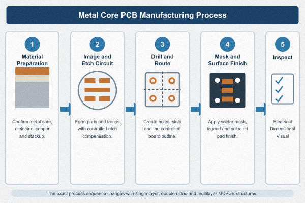
The metal core PCB manufacturing process begins with stackup and material confirmation. The circuit copper is imaged and etched, the dielectric and metal are prepared for the specified construction, and drilling or routing is performed in a sequence that protects isolation around the metal. Solder mask, legend and surface finish are then applied according to the assembly requirements.
Process details change with the structure. A single-layer board does not require the same interconnection route as a double-sided or multilayer board. Our engineering review therefore ties each major operation to the approved drawing instead of treating all metal core boards as one standard recipe.
Which Surface Finishes and Solder Masks Are Available?
Available surface-finish options include ENIG, flash gold, hard gold, gold finger, selective gold, ENEPIG, ENIPIG, HASL, lead-free HASL, OSP, immersion silver and immersion tin. The choice should match component pitch, soldering process, storage, wire bonding or contact requirements. Not every finish is appropriate for every pad function.
Solder-mask selection also affects optical appearance, assembly inspection and thermal exposure. Send the required color, gloss, marking color and any LED reflectivity requirement. If the board uses exposed metal edges or a housing contact surface, show those areas clearly so the mask and finish boundaries are not inferred from the circuit artwork.
How Do We Inspect Metal Clad PCBs?
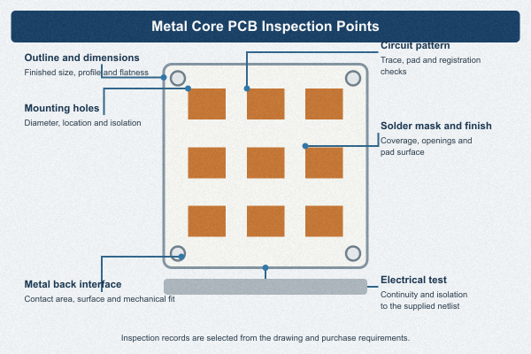
Inspection must follow the feature that matters. For a metal clad PCB, we can review conductor dimensions, finished holes, outline, solder mask, surface finish and electrical continuity. Cross-sections can be assigned when the dielectric interface, plated hole or multilayer registration needs physical verification. Flatness and mechanical dimensions matter when the metal back must contact a housing or heatsink.
Electrical testing confirms the circuit against the supplied netlist; it does not measure thermal resistance. A thermal requirement needs an agreed material specification, coupon or application-level validation method. The purchase drawing should state which records are required with the shipment, such as dimensional reports, electrical-test confirmation, material traceability or section results.
What Files Should You Send an MCPCB Manufacturer?
As an MCPCB manufacturer, we can quote more accurately when the engineering package defines both the circuit and the thermal-mechanical interface. Gerber or ODB++ data alone may not show which metal surface touches the enclosure, the required dielectric performance or the inspection records expected at delivery.
| RFQ input | What to include | Decision it supports |
|---|---|---|
| Fabrication data | Gerber/ODB++, drill files, netlist and drawing | Circuit, hole, outline and electrical-test review |
| Stackup | Copper weights, dielectric, metal type and thickness | Material and manufacturing-route confirmation |
| Thermal requirement | Power map, component pads, target interface and cooling method | Thermal-path and structure review |
| Mechanical requirement | Finished dimensions, flatness, holes, countersinks and contact surfaces | Housing fit and assembly planning |
| Commercial input | Prototype and production quantities, delivery target and annual demand | Panelization, lead-time and quotation basis |
| Quality output | Required reports, coupons, traceability and acceptance criteria | Inspection plan and shipment documentation |
Why Choose Best Technology as Your Metal Core PCB Manufacturer?
EBest Circuit (Best Technology) has more than 18 years of PCB manufacturing experience and serves more than 1,200 customers. Our published capability covers metal core, FR4, heavy-copper, flex, rigid-flex, HDI, ceramic and other special PCB technologies. For MCPCB projects, this range helps when the final product needs more than one board technology or when a thermal board must be reviewed alongside assembly and enclosure constraints.
We support prototypes, small batches and volume production, with more than 1,000 different boards manufactured per month and a listed monthly capacity of 28,900 square meters. A qualified single-layer MCPCB order can be supported with a fastest-case lead time as short as 24 hours, but actual lead time depends on material, stackup, dimensions, finish, quantity and engineering approval. Send your drawing to sales@bestpcbs.com; as your metal core PCB manufacturer, we will review the build before confirming capability, price and delivery.
Metal Core PCB Manufacturer FAQs
Can you manufacture both aluminum and copper core PCBs?
Yes. Our published MCPCB range includes aluminum and copper core options, as well as steel and stainless-steel core constructions. The final material must be confirmed against the stackup, thermal requirement, dimensions and quantity.
Can an MCPCB have more than one circuit layer?
Yes. We manufacture two-layer, double-sided and multilayer MCPCB structures in addition to single-layer boards. The layer order and the location of the metal core must be shown on the drawing.
Is a higher dielectric thermal conductivity always better?
Not by itself. Thermal conductivity, dielectric thickness, electrical isolation, pad area and the external cooling interface work together. Compare the complete thermal path and the conditions under which the material value is specified.
How do I obtain a quotation?
Send the fabrication data, stackup, metal and dielectric requirements, copper weights, quantity, delivery target and required inspection records. We will review the package and identify any missing thermal or mechanical information before quotation.
You may also like

Tags: MCPCB, Metal Core PCB, PCB manufacturer