
PCB resin recession is a cross-sectional condition in which resin has receded from its expected boundary around a drilled or plated feature, leaving glass bundles or adjacent structures comparatively exposed. It is not automatically the same as copper-to-hole-wall pullaway, resin smear or a lamination void.
The practical question is not simply whether one dark or recessed area appears in a micrograph. Engineers must confirm the morphology, preparation quality, extent, test history and applicable acceptance criteria before assigning a root cause or lot disposition. A defensible investigation separates observation from interpretation and interpretation from corrective action.
What PCB Resin Recession Looks Like
In a prepared microsection, resin recession appears as resin pulled back or missing relative to nearby glass reinforcement, copper or the intended laminate boundary. The feature may be local around a hole wall or visible near internal-layer edges. Its shape and position should be documented across the entire section, not inferred from a tightly cropped image.
Look for exposed glass ends, a recessed resin boundary and whether the copper barrel remains intact and supported. Record the layer, quadrant, depth and length of the indication. Compare more than one hole and, when possible, compare suspect material with a known-good construction prepared by the same method.
Polishing relief can imitate recession. Soft resin and hard glass or copper remove at different rates during specimen preparation. If the indication changes substantially with preparation technique or appears only at a poorly supported edge, repeat the section before treating it as a production defect.
Resin Recession vs Hole Wall Pullaway, Smear, Starvation, and Voids
Classify the material or interface that is missing, displaced or separated before selecting corrective action.
| Finding | Defining location | Key visual clue | Investigation focus |
| Resin recession | Resin boundary near glass/copper | Resin sits back while reinforcement or adjacent geometry is exposed | Material, lamination, thermal history and preparation artifact |
| Hole wall pullaway | Copper-barrel-to-dielectric interface | Gap follows the interface beside an otherwise recognizable barrel | Interface preparation and interconnect reliability |
| Resin smear | Drilled wall or inner-layer connection | Resin coats or obscures copper that should be exposed | Drilling heat and desmear effectiveness |
| Resin starvation | Broader laminate region | Insufficient resin wet-out around reinforcement | Prepreg selection, layup and resin flow |
| Lamination void | Inside the dielectric | Enclosed cavity rather than a recessed surface boundary | Layup, vacuum, pressure and entrapped volatiles |
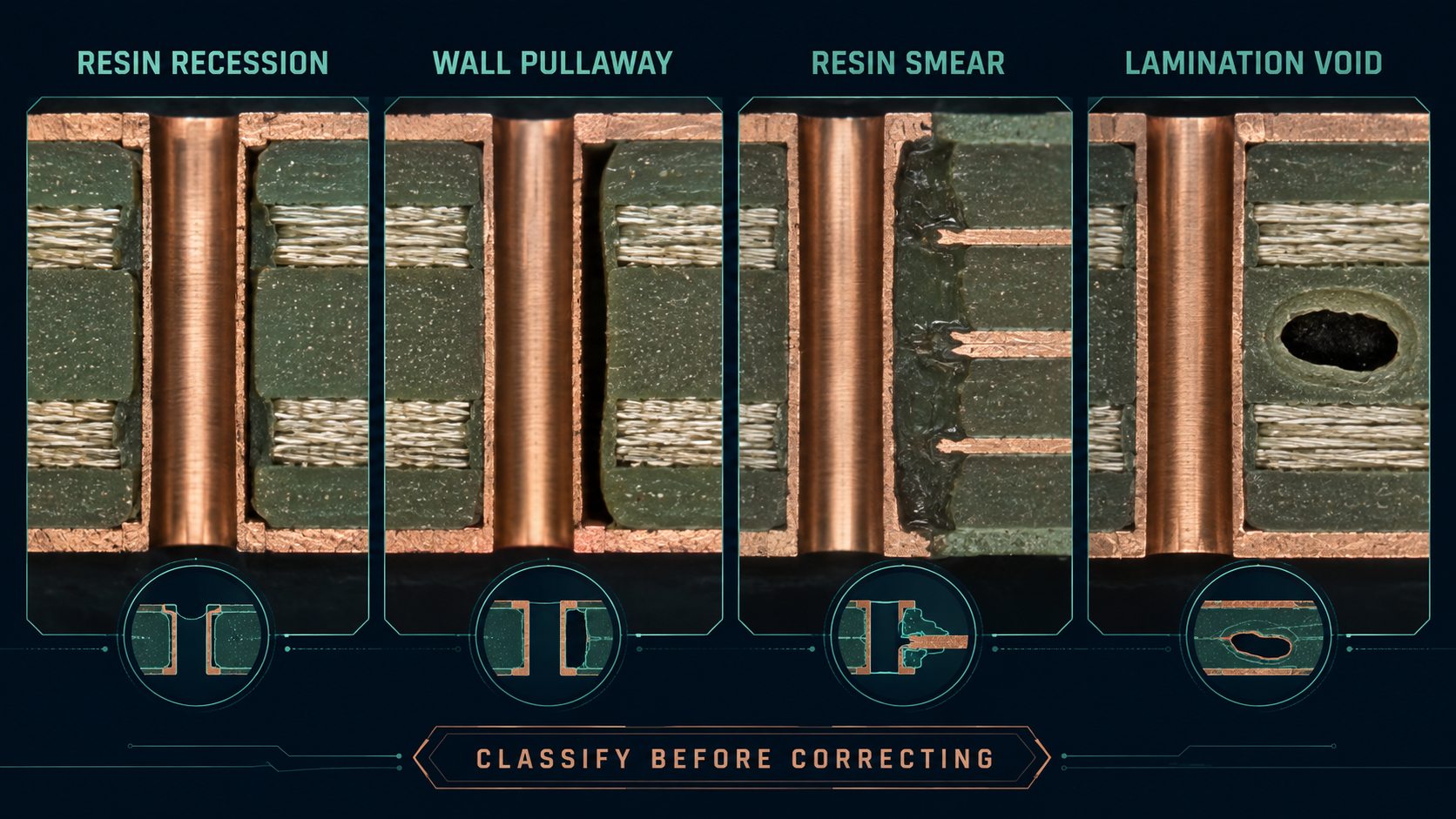
For a focused explanation of copper-interface separation, use our PCB hole wall pullaway guide. The distinction matters because increasing desmear, changing a press cycle or altering a plating process are not interchangeable remedies.
Why Recession Can Become More Visible After Thermal Stress
Thermal exposure can change the apparent or actual geometry because resin, glass and copper respond differently to heat, moisture and repeated expansion. This does not mean thermal stress is always the original cause. It may reveal a pre-existing material or process weakness, exaggerate a preparation-related feature, or create a condition beyond the product’s normal use.
Always identify whether the section was examined as received, after baking, after solder float, after reflow simulation, or after another conditioning sequence. Record temperature, dwell, cycles, ramp, cooling and moisture conditioning. Without that information, a before/after comparison cannot be reproduced.
When the concern appeared after assembly, include the actual reflow and rework history. Multiple local rework cycles may produce a different exposure from one qualified production profile. Our solder float test guide explains why the specified test method and post-stress evidence must travel together.
A Microsection Sequence That Preserves Evidence
A controlled sequence should produce comparable sections without consuming every suspect sample.
- Identify part, revision, lot, panel position, hole type and downstream history.
- Reserve untested specimens and known-good comparison material.
- Photograph the board and mark the intended section plane.
- Mount and support the specimen so the hole remains centered and edges are protected.
- Grind and polish progressively, avoiding excessive heat or pressure.
- Capture a full-hole overview before higher-magnification details.
- Record resin, glass, barrel and inner-layer geometry separately.
- Apply any agreed thermal stress to a separate or documented specimen group.
- Compare frequency and extent across locations, lots and conditions.
- Retain images, raw measurements, unused samples and the preparation record.
A single attractive micrograph is not a sampling plan. For broader specimen and report requirements, see how PCB microsection analysis finds hidden defects.
Unsure whether the section shows recession or another defect?
Send the original overview and detail micrographs, stackup, material callout, drill data, sample condition and thermal history. EBest Circuit can identify what additional evidence is needed before a process change or rebuild.
Material and Lamination Conditions to Investigate
Resin recession can reflect the material system, its condition and the way the multilayer was laminated, but no one factor should be declared causal without correlation.
| Area | Question | Evidence |
| Material construction | Is the prepreg/resin system appropriate for the stackup and thermal exposure? | Controlled stackup, material designation and supplier lot |
| Storage and handling | Could moisture or out-of-control storage affect behavior? | Receiving, storage, floor-life and bake records |
| Layup | Is resin distribution consistent around dense copper and drilled regions? | Artwork, copper balance, prepreg selection and panel map |
| Press cycle | Did temperature, pressure, vacuum and cure remain within the controlled recipe? | Actual press chart and lot traveler |
| Thermal history | Was the construction exposed beyond the qualified sequence? | Fabrication, assembly, rework and test profiles |
Compare the finding with resin-rich and resin-poor areas, different panel locations and more than one material lot. If the feature follows copper density rather than the drill tool, lamination and local resin-flow evidence deserve closer attention.
Drilling and Hole Preparation Checks
Drilling and desmear determine the surface that later receives metallization, so their records help distinguish true recession from smear, roughness or preparation damage.
- Review drill diameter, tool type, hit count and actual tool-change interval.
- Check feeds, spindle speed, entry/backer materials and panel stack height.
- Inspect unplated hole walls when retained process coupons are available.
- Compare high-copper and low-copper panel regions.
- Review desmear chemistry, concentration, temperature, dwell, loading and agitation.
- Confirm conditioning and metallization followed the controlled process window.
- Look for smear, glass-fiber protrusion, gouging, voids and barrel discontinuity as separate findings.
Do not respond to suspected recession by simply increasing chemical attack. An aggressive change may alter the hole wall in another way. Trial the cause-specific adjustment and compare controlled sections.
How to Read Extent, Location, and Frequency
The decision value of a finding comes from its distribution, not only its maximum-looking example. Record how many inspected holes show the condition, where it appears around each circumference, its approximate extent and whether it clusters by layer, panel region, hole size or thermal condition.
A repeated feature at the same depth can point toward construction or process interaction. A feature concentrated near one panel edge may justify reviewing press or chemistry uniformity. A correlation with one drill tool suggests a different path. No correlation is also evidence: it means the investigation should remain open rather than forcing the first explanation.
Use measurement methods agreed by the customer, supplier and applicable specification. Avoid extracting a universal acceptance limit from an unrelated image or article; product class and customer requirements control the final disposition.
Containment Before Root Cause Is Confirmed
Containment protects product and evidence while the investigation is still uncertain.
- Identify the suspect lot boundaries and all downstream locations.
- Segregate suspect, screened, accepted and rebuilt material.
- Preserve traceability to panels, materials, drill tools and press/plating batches.
- Reserve representative samples before destructive analysis.
- Define any temporary screen and document what it cannot detect.
- Stop uncontrolled extra thermal exposure that could change the evidence.
- Assign disposition authority and a deadline for the next evidence review.
Containment does not prove acceptability. If product has already entered assembly or the field, risk evaluation must include application, thermal/mechanical stress and the possibility of associated interconnect defects.
Cause-Specific Corrective Actions and Verification
A corrective action is credible only when it follows confirmed evidence and passes a controlled verification.
| Evidence pattern | Action direction | Verification |
| Material or storage-lot correlation | Correct material control, conditioning or approved construction | Traceable comparison build and repeat sections |
| Press-cycle or panel-position correlation | Restore recipe, vacuum, pressure or loading uniformity | Actual press chart plus mapped microsections |
| Drill-tool correlation | Adjust tool-life/parameter control | Controlled drill trial before and after plating |
| Preparation artifact | Correct mounting, grinding and polishing method | Independent repeat sections |
| Excess downstream thermal exposure | Control assembly/rework profile | Qualified profile followed by agreed inspection |
Changing material, drilling, desmear and lamination simultaneously can hide the true contributor. When practical, isolate variables and retain the evidence that proves the improved outcome is repeatable.
What to Send for Supplier Engineering Review
A review can move faster when design data, specimen identity and process history arrive together.
- Gerber or ODB++, fabrication drawing and controlled revision;
- stackup, material designation and prepreg construction;
- NC drill files, drill table and relevant hole structures;
- product class, customer specification and acceptance question;
- lot, panel and sample traceability;
- full-resolution overview/detail micrographs;
- sample preparation method and operator/lab identity;
- thermal conditioning, soldering and rework profiles;
- quantity affected, containment status and required response date;
- target build quantity and delivery requirement if a rebuild is requested.
Prepare a controlled PCB review or rebuild package
Include the design files, material/stackup, drill data, acceptance requirement, original images and thermal history. We will separate the immediate containment question from DFM, inspection and production requirements.
FAQ About PCB Resin Recession
Is resin recession always a rejectable PCB defect?
No universal answer applies. The governing product/customer requirement, morphology, extent, sampling, associated defects and end-use risk determine disposition.
Is resin recession the same as hole wall pullaway?
No. Recession describes resin pulled back from its expected boundary. Pullaway describes separation at the copper-barrel-to-dielectric interface. Both can appear near a plated hole.
How is resin recession different from resin smear?
Smear is unwanted resin left on a drilled wall or inner-layer copper. Recession is resin absent or set back relative to surrounding geometry.
Can polishing create apparent resin recession?
Yes. Differential removal of soft resin, glass and copper can produce relief. Repeat preparation and comparison specimens help test that explanation.
Can visual inspection find resin recession?
Usually not from the PCB surface. A controlled cross-section is normally needed to see and interpret the internal geometry.
Does thermal stress cause every case?
No. Thermal exposure may reveal or enlarge a condition, but material, lamination, drilling, preparation and specimen artifacts must also be investigated.
What should a microsection image include?
Include a full-hole overview and detailed views with scale or magnification, sample identity, orientation, preparation condition and thermal history.
How many holes should be inspected?
The sampling plan should reflect the governing requirement, lot risk and observed distribution. One hole cannot normally establish lot-wide frequency.
Can electrical test prove the laminate interface is acceptable?
No. Electrical continuity can pass while a structural finding remains. Use electrical results with microsection, process and reliability evidence.
What proves a corrective action worked?
A traceable controlled build using the confirmed change, followed by the agreed sampling, conditioning and inspection sequence, provides stronger proof than a single passing section.
Final Acceptance and Prevention Checklist
- Confirm the feature is real and not specimen-preparation relief.
- Differentiate recession from pullaway, smear, starvation and voids.
- Define sample count, distribution and thermal condition.
- Use the correct customer or product acceptance requirement.
- Preserve lot, panel, material and process traceability.
- Link root cause to physical and process evidence.
- Verify the specific correction on a controlled build.
- Update drawings, inspection plans and supplier records where needed.
Get an evidence-led PCB manufacturing review.
Send Gerber or ODB++, stackup, drill files, material callout, micrographs, lot history, thermal profile, quantity and target delivery to sales@bestpcbs.com, or use the PCB quote form. EBest Circuit will identify missing evidence and align inspection requirements before production or a corrective rebuild.
You may also like







Tags: pcb failure analysis, PCB microsection, PCB Quality Control