





How can a microphone PCB support clearer sound, lower noise, and more stable production? In audio devices, voice control modules, intercom systems, medical electronics, automotive voice units, and industrial acoustic equipment, the board plays an important role in signal transfer and assembly quality.
A well-planned microphone PCB helps control routing, grounding, power stability, microphone placement, and acoustic alignment. This guide explains board types, layout methods, mounting steps, prototype checks, assembly control, testing, and custom manufacturing support from EBest.
What Is a Microphone PCB Board?
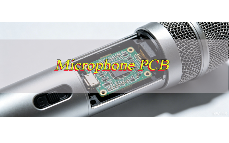
A microphone PCB board is a printed circuit board used to mount microphone parts and connect them with the rest of an electronic product.
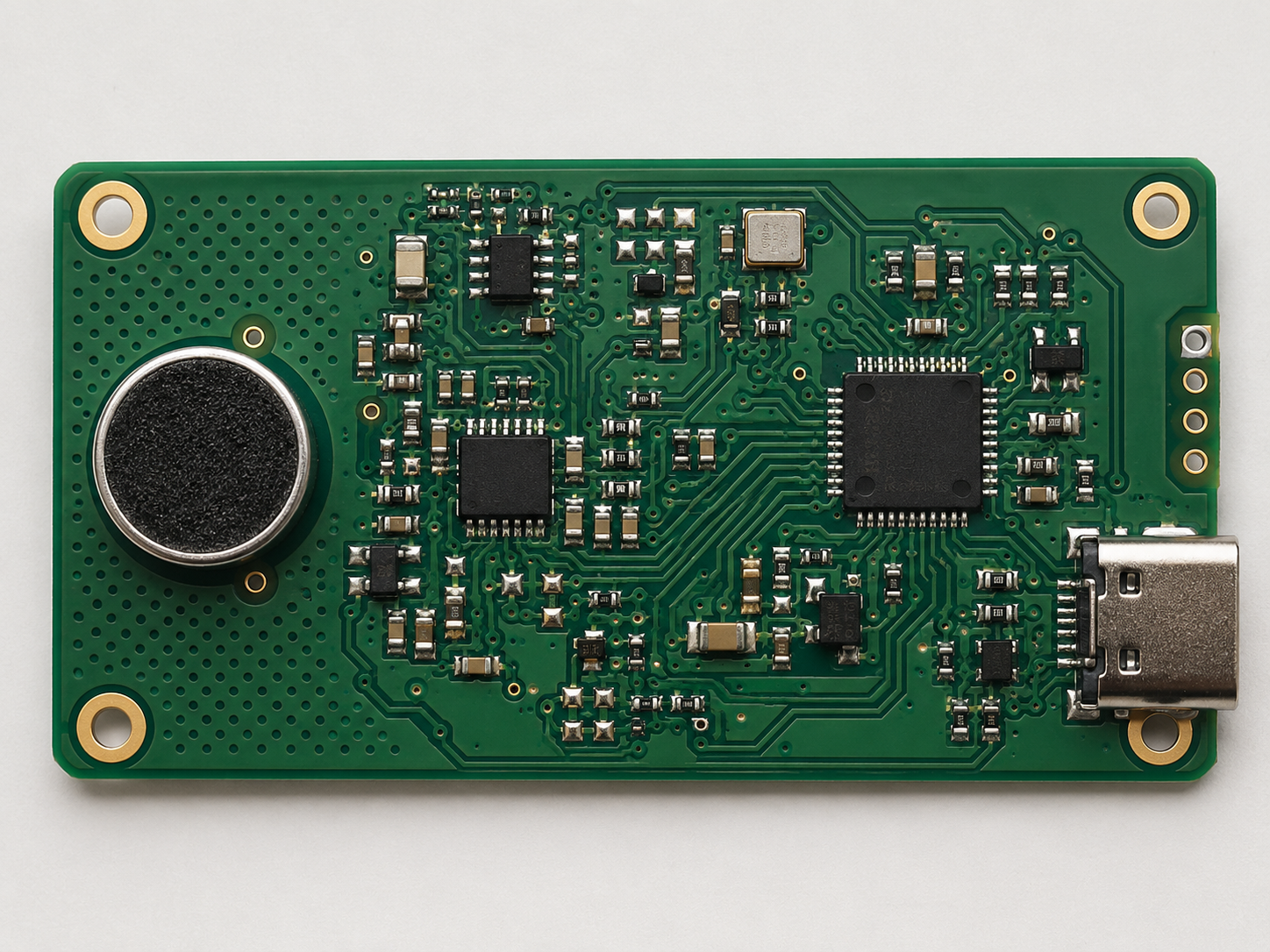
It may carry a MEMS microphone, condenser microphone capsule, electret microphone, preamp circuit, filtering parts, connector, power circuit, and test points. In some products, the board is very small. In others, it may be part of a larger audio, control, or communication system.
Its main job is to help the sound signal move from the microphone element to the processing circuit. Since this signal is usually weak at the beginning, the board layout should reduce noise, protect the input path, and keep power stable.
A good microphone board should also match the product structure. The acoustic hole, connector direction, screw holes, board outline, gasket position, and housing opening should all be checked before production.
What Types of Microphone PCB Boards Are Commonly Used?
Different audio products use different microphone board structures. The right choice depends on the microphone element, signal output, available space, acoustic design, and assembly method.
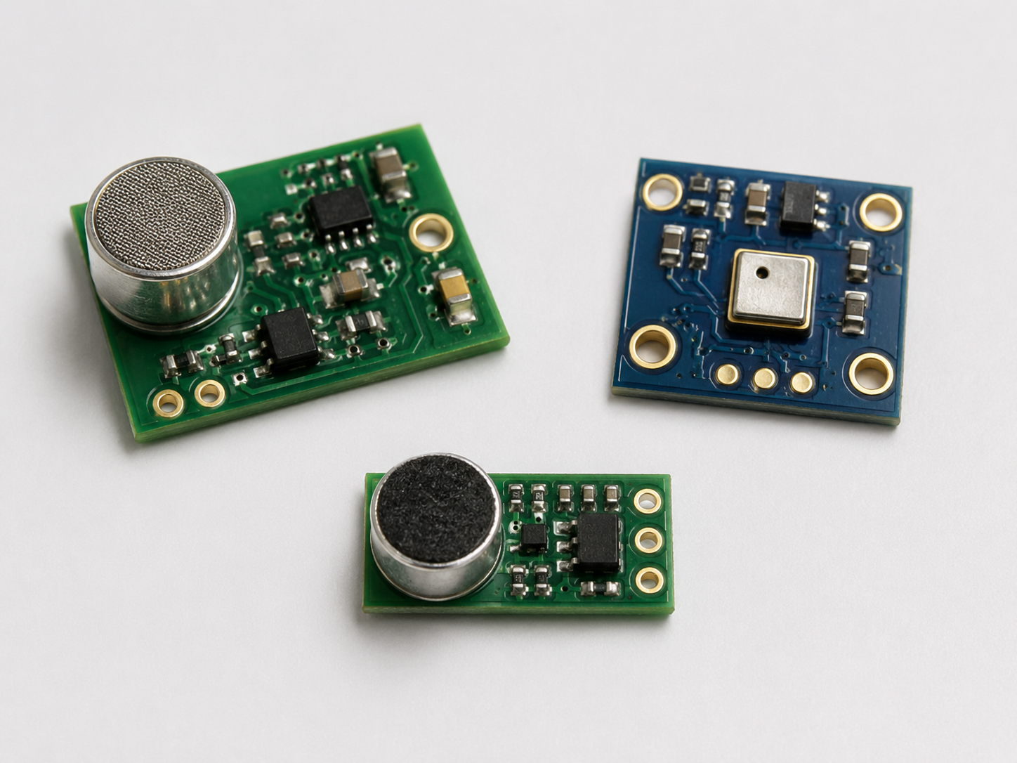
- Condenser Microphone PCB
A condenser microphone PCB is often used in recording devices, communication equipment, studio microphones, and professional audio products. It usually supports bias voltage, impedance conversion, signal filtering, and low-noise routing. - MEMS Microphone PCB Board
MEMS microphone boards are widely used in earbuds, smart speakers, wearable devices, IoT products, and compact voice modules. This type usually requires SMT assembly, accurate acoustic hole alignment, and controlled reflow soldering. - Electret Microphone PCB Board
An electret microphone PCB board is common in headsets, intercom systems, toys, small audio modules, and simple voice pickup devices. It usually includes a bias resistor, coupling capacitor, connector, and basic filtering circuit. - Analog Microphone PCB
An analog microphone board sends a continuous analog signal to the next audio circuit. It is often used in products that require simple signal processing, flexible circuit adjustment, or traditional audio input design. - Digital Microphone PCB
A digital microphone board is often used with MEMS microphones that output digital signals such as PDM or I²S. It is suitable for compact smart devices where space-saving layout and stable digital signal routing are important. - Microphone Array PCB
A microphone array board uses two or more microphones on one PCB to improve voice pickup direction, noise reduction, or far-field sound capture. It is commonly used in smart speakers, conference systems, automotive voice modules, and voice control devices.
What Are Best Practices for Microphone PCB Layout?
Good layout helps protect weak audio signals from noise, unstable power, and unwanted interference. In a microphone circuit, the input signal is usually very small before amplification, so routing, grounding, component placement, and acoustic structure should be planned carefully from the beginning.
- Keep microphone input traces as short as possible
The trace from the microphone output to the first amplifier, codec, ADC, or connector should be short and direct. Long traces can act like antennas and pick up noise from nearby power, RF, clock, or digital circuits. - Separate audio traces from noisy circuits
Microphone signal traces should stay away from switching regulators, wireless modules, crystal clocks, motor drivers, LED drivers, USB lines, and other high-speed or high-current areas. If the board space is limited, place the microphone circuit in a quieter area of the PCB. - Use a clean and stable ground path
A poor ground path may create hum, noise, or unstable signal levels. For analog microphone circuits, keep the return path short and predictable. Avoid forcing low-level audio signals to share the same ground return path with noisy power circuits. - Place decoupling capacitors close to active components
Power filtering parts should be placed near microphone ICs, preamp ICs, codecs, and ADCs. This helps stabilize the supply voltage and reduce power ripple before it reaches sensitive audio circuits. - Keep high-impedance areas clean and protected
Condenser and electret microphone circuits may include high-impedance input areas. These areas should be short, clean, and away from contamination-prone zones. Flux residue, moisture, or dust may affect signal stability in sensitive designs. - Avoid routing noisy traces under the microphone section
Clock lines, high-speed digital traces, RF lines, and switching power traces should not pass under the microphone input circuit or sound port area. If crossing is unavoidable, use proper layer planning and grounding to reduce coupling. - Plan the acoustic opening with the layout
The sound port, PCB hole, gasket, enclosure opening, and microphone position should align accurately. A good electrical layout may still perform poorly if the acoustic path is blocked, shifted, or poorly sealed. - Leave enough space for assembly and inspection
Do not place tiny passive parts too close to the microphone port, connector edge, or enclosure wall. Keep enough clearance for SMT placement, solder paste printing, AOI inspection, hand soldering when required, and fixture testing. - Add test points where they are useful
Test points for power, ground, signal output, and control lines can make prototype validation and production testing easier. They should be placed where test probes can access them without touching sensitive microphone parts. - Match the layout with the final housing
A microphone board is often used inside a compact product. Board outline, connector direction, screw holes, acoustic hole, cable exit, and enclosure clearance should be reviewed together before fabrication.
How Should a Microphone PCB Be Mounted?
Mounting is not only a mechanical step. It affects soldering quality, sound pickup, acoustic sealing, enclosure fit, and long-term reliability. Before mounting a microphone PCB, the microphone type, sound port direction, board outline, gasket position, and housing opening should be checked together.
Step 1: Confirm the microphone package and port direction
First, check whether the microphone is MEMS, condenser, electret, SMD, through-hole, top-port, or bottom-port. A top-port microphone receives sound from the top side of the part, while a bottom-port microphone receives sound through a hole in the PCB. This difference directly affects board hole design and enclosure alignment.
Step 2: Review the footprint and pad design
The land pattern should follow the component datasheet and assembly process. Pad size, solder mask opening, stencil aperture, and spacing should be checked before production. An unsuitable footprint may cause solder bridging, weak solder joints, floating parts, or placement shift.
Step 3: Align the acoustic hole correctly
For a bottom-port microphone, the PCB hole must align with the microphone sound inlet. The hole should not be blocked by solder mask, copper, adhesive, gasket material, or enclosure ribs. For a top-port microphone, the housing opening should sit directly above the sound port.
Step 4: Control solder paste volume
Solder paste should be controlled carefully around microphone pads. Too much solder may lift the part, affect sealing, or create bridging. Too little solder may reduce joint strength. For MEMS microphones, stencil design and reflow control should follow the part supplier’s recommendations.
Step 5: Match the board with the enclosure
The PCB should fit the final housing without stress. Screw holes, clips, posts, connectors, cable exit, gasket, and sound opening should be checked as one structure. If the board is bent or pressed after installation, solder joints and microphone performance may be affected.
Step 6: Use proper gasket or sealing design when required
Many microphone products use a rubber gasket or acoustic sealing structure between the board and housing. The gasket should guide sound into the microphone port without air gaps, compression loss, or misalignment. Poor sealing can reduce sensitivity or cause inconsistent sound pickup.
Step 7: Protect the sound port during assembly
Dust, solder balls, flux, cleaning liquid, adhesive, and coating material should not enter the microphone opening. If conformal coating or cleaning is used on the PCBA, the microphone area should be protected according to the process requirement.
Step 8: Avoid mechanical stress after mounting
Do not place screws, clips, or housing pressure points too close to the microphone part unless the structure has been verified. Mechanical stress may cause board warpage, solder joint strain, or acoustic leakage.
Step 9: Inspect the mounted board before testing
After assembly, check the solder joints, port alignment, board seating, gasket position, connector orientation, and housing fit. Visual inspection and basic electrical checks should be completed before sound-related testing.
Step 10: Run a functional sound check when required
For finished microphone PCB assemblies, a functional test can check power, signal output, noise level, sensitivity, or basic pickup response. This helps confirm that both the electrical path and acoustic path are working properly.
What Are Common Challenges in Microphone PCB Design and How Can They Be Solved?
Microphone circuits work with small signals, so board design should control noise, grounding, placement, power, and mechanical fit from the beginning.
- Noise from nearby circuits
Keep the input path away from RF, switching power, clock, and high-current areas. Add proper filtering and grounding. - Weak signal stability
Use short routing, stable power rails, and close power filtering near active parts. - Hum from poor grounding
Plan ground return paths carefully and avoid sharing noisy current paths with low-level audio signals. - Wrong sound port position
Check microphone direction, PCB hole, gasket, and enclosure opening before fabrication. - Limited board space
Use compact placement while keeping enough room for test pads, connector access, and assembly clearance. - Preamp sensitivity
Keep the input area clean, reduce trace length, and separate the gain stage from noisy circuits. - Wrong surface finish or board thickness
Choose board thickness and finish based on assembly, storage, connector type, and final housing structure. - Production variation
Use DFM review before fabrication to check spacing, pad size, drill size, solder mask clearance, and assembly feasibility.
How Can Microphone PCB Prototyping Reduce Design and Assembly Risks?
Prototype production helps verify the circuit, structure, assembly process, and sound path before larger production begins. It is a practical way to find issues early.
- Circuit verification
A prototype can reveal gain issues, noise, wrong part values, unstable power, or signal path errors. - Housing fit check
Board outline, screw holes, connector position, sound hole, and cable direction can be checked with the real enclosure. - Sound pickup review
Teams can test signal level, sensitivity, noise behavior, and basic audio quality. - SMT process review
Prototype assembly helps confirm solder paste, placement accuracy, reflow result, and port protection. - BOM review
Microphone parts, preamp ICs, connectors, resistors, capacitors, and replacement choices can be checked early. - Test pad validation
Test points and fixture access can be adjusted before the final production version. - Lower rework risk
Finding issues during prototype work is easier than changing the board after larger assembly batches.
What Should Be Controlled During Microphone PCB Assembly?
Assembly control is important because microphone components may be sensitive to heat, dust, solder residue, and mechanical stress. A stable process helps improve repeatability.
- Solder paste printing
Stencil thickness and aperture design should match pad size and microphone package requirements. - SMT placement accuracy
Placement should be controlled for MEMS microphones, ICs, connectors, and small passive parts. - Sound port protection
The microphone port should be kept free from solder paste, dust, flux, and cleaning residue. - Reflow temperature profile
The temperature curve should match solder paste requirements and component limits. - Part sourcing control
Microphone parts, ICs, resistors, capacitors, and connectors should match the BOM and approved replacement list. - Connector soldering
Board-to-board connectors, cable connectors, and wire harness areas should be checked for alignment and strength. - AOI inspection
AOI can detect missing parts, wrong polarity, shifted components, and solder issues. - Functional test
The assembled board can be checked for power, signal output, noise level, and basic microphone response when required.
What Quality Control and Testing Standards Are Used for Microphone PCB Production?
Quality control for microphone PCB production should cover bare board fabrication, material checking, SMT assembly, soldering quality, cleanliness, electrical performance, and functional testing. Since microphone circuits handle weak signals, small defects in routing, soldering, grounding, or acoustic alignment may affect final sound pickup.
- DFM Review Before Production
Before fabrication starts, Gerber files, drill files, solder mask openings, pad sizes, spacing, board outline, acoustic holes, and connector areas should be reviewed. This helps reduce layout risks before the board enters production. - Incoming Material Inspection
PCB laminate, copper foil, solder mask, surface finish, solder paste, microphone parts, ICs, connectors, and passive components should be checked before use. For audio boards, part consistency and correct BOM matching are important. - Bare Board Electrical Testing
The finished bare board should be tested for open circuits and short circuits. This step confirms that the copper traces and connections match the design before assembly. - Visual Inspection and AOI
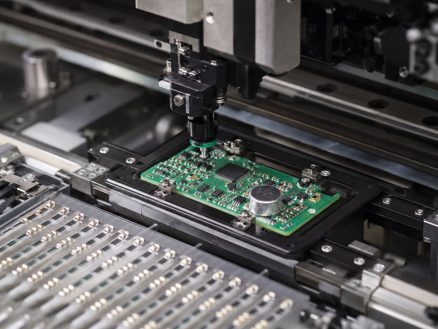
After SMT assembly, AOI can check missing parts, wrong polarity, shifted components, solder bridging, insufficient solder, and other visible assembly defects. This is especially useful for MEMS microphones, small resistors, capacitors, and fine-pitch ICs. - Soldering Quality Inspection
Solder joints should be checked according to accepted PCBA workmanship standards, such as IPC-A-610 and J-STD-001 when applicable. The focus is solder wetting, joint shape, component alignment, bridging, tombstoning, and solder residue. - X-Ray Inspection When Required
X-ray inspection may be used for hidden solder joints, bottom-terminated components, BGA packages, or dense assembly areas. It helps find voids, bridges, and poor solder connections that cannot be seen from the surface. - Cleanliness Control
Microphone boards should be kept clean around microphone ports, high-impedance input areas, and acoustic openings. Flux residue, dust, cleaning liquid, or solder balls near the sound port may affect signal stability or acoustic performance. - Functional Electrical Testing
The assembled board can be powered and checked for voltage, current, signal output, grounding, and basic circuit function. For microphone circuits, the signal path from microphone input to output connector or processing circuit should be verified. - Audio or Acoustic Function Test
When required, the board can be tested for microphone response, noise level, sensitivity, signal level, or basic sound pickup. This test helps confirm that both the electrical path and acoustic path are working correctly. - Reliability Testing for Specific Applications
Some projects may require thermal cycling, vibration testing, humidity testing, drop testing, or aging tests. These checks are often used when the board will work in automotive, medical, industrial, or outdoor electronic products. - Compliance and Process Standards
Common references may include IPC-A-600 for bare PCB quality, IPC-A-610 for assembled board acceptance, J-STD-001 for soldering process control, RoHS for restricted substances, and ISO 9001-based quality management. - Traceability Records
Production records, material batch information, inspection results, test data, and assembly process details should be kept for repeat orders and quality review. This is helpful when the same microphone board moves from prototype to mass production.
How Do You Choose a Reliable Microphone PCB Manufacturer?
A reliable supplier should understand fabrication, assembly, part sourcing, testing, and production communication. For audio boards, the supplier should also pay attention to low-level signal routing, acoustic holes, and component handling.
- Fabrication capability
The supplier should support standard FR4, multilayer boards, thin boards, impedance-related boards, and other board structures when required. - Assembly capability
SMT assembly, connector soldering, inspection, and testing support help deliver a finished PCBA. - DFM review
A useful supplier will review files before production and point out risks in pads, spacing, holes, solder mask, or assembly areas. - Component sourcing support
Microphones, preamp ICs, connectors, and passive parts should be sourced with clear part matching and supply control. - Prototype and mass production support
Early builds and larger production should both be supported by the same production flow when possible. - Delivery support
Ask about prototype lead time, assembly lead time, and urgent order service when schedule matters. - Testing ability
Bare board testing, AOI, X-ray when required, and functional checks can improve production confidence. - Clear communication
Fast feedback on Gerber files, BOM issues, replacement parts, and delivery dates helps keep the project moving.
Why Choose EBest for Microphone PCB Design, Prototype, and Assembly?
EBest Circuit supports one-stop PCB and PCBA service, including PCB design, PCB prototype, mass production, component sourcing, and PCB assembly. The company was founded on June 28, 2006, and has more than 20 years of experience in PCB solutions. Here are reasons why choose EBest for microphone PCB manufacturer:
- Design support before production
EBest can review manufacturability, layout risks, pad design, drilling, spacing, solder mask, and assembly requirements before fabrication. - Prototype fabrication
Prototype builds help verify circuit function, board fit, sound path, assembly process, and test access. - Mass production support
EBest supports repeat production for audio, communication, industrial, medical, automotive, and smart electronics projects. - Component sourcing
Microphones, ICs, connectors, resistors, capacitors, and related parts can be sourced together with assembly service. - PCB assembly
SMT assembly, soldering, inspection, and testing help turn bare boards into functional PCBA products. - Wide board capability
EBest’s product range includes FR4 PCB, multilayer PCB, metal core PCB, ceramic PCB, flexible and rigid-flex PCB, high frequency PCB, HDI PCB, heavy copper PCB, high-speed PCB, and impedance control PCB. - Fast delivery support
EBest provides urgent board service, with some urgent boards shipped within 24 hours when project conditions allow. - Quality support
The listed certifications include ISO 9001:2015, ISO 13485:2016, IATF 16949, AS9100D, REACH, RoHS, and UL. - What EBest can provide
EBest can provide PCB design support, prototype fabrication, mass production, component sourcing, PCB assembly, DFM review, material suggestion, surface finish selection, testing, and production follow-up.
FAQs About Microphone PCB Board
Q1: What should be checked before designing a PCB mount microphone Board?
A1: For a PCB mount microphone Board, the sound port direction, pad size, solder paste opening, acoustic hole, and enclosure opening should be checked together. If the microphone is bottom-port, the PCB hole must align with the sound inlet. If it is top-port, the housing opening should sit above the microphone.
Q2: Why is a microphone preamp PCB important in audio products?
A2: A microphone preamp PCB boosts the weak microphone signal before it reaches an audio processor, ADC, codec, mixer, or control circuit. Good preamp layout helps reduce noise, stabilize gain, and improve signal clarity before later processing.
Q3: What makes a vintage microphone PCB different from a modern microphone board?
A3: A vintage microphone PCB is usually made for restoration, repair, or circuit replacement. It often has to match the original capsule type, board shape, connector location, and circuit style. Modern boards usually focus more on compact layout, SMT assembly, and stable production.
Q4: What information should be prepared before ordering a microphone board prototype?
A4: Gerber files, BOM, board thickness, copper weight, surface finish, quantity, assembly notes, microphone part number, datasheet, and test requirements are useful. If the board has an acoustic hole or special enclosure fit, those details should also be included.
Q5: Why does microphone board layout affect sound quality?
A5: Microphone signals are weak before amplification, so long traces, unstable grounding, nearby switching power circuits, RF lines, or poor filtering may add noise. Short input routing, clean ground paths, and proper circuit separation can improve sound pickup stability.
Q6: Can MEMS and condenser microphone boards use the same layout method?
A6: Not exactly. MEMS microphone boards often focus on SMT placement, acoustic port alignment, and compact routing. Condenser microphone boards usually require more attention to bias voltage, high-impedance input areas, low leakage paths, and analog signal cleanliness.
Q7: What tests are useful after microphone board assembly?
A7: Common checks include visual inspection, AOI, electrical testing, power-on testing, signal output checks, and basic sound pickup testing. For more demanding products, noise level, sensitivity, humidity, vibration, or aging tests may also be required.
Q8: What surface finish is commonly used for microphone boards?
A8: ENIG, OSP, and HASL may be used depending on pad design, storage time, assembly method, and product requirements. ENIG is often selected for fine-pitch parts or flatter soldering pads, while OSP and HASL may suit simpler board designs.
Q9: Can one supplier handle fabrication, parts sourcing, and assembly for microphone boards?
A9: Yes. For production projects, combining PCB fabrication, component sourcing, SMT assembly, inspection, and testing can make the process smoother. It also helps reduce file transfer mistakes, BOM mismatch, and production communication delays.
How Can You Get a Fast Quote for a Custom Microphone PCB?
Your microphone board deserves more than basic fabrication. If your project involves microphone PCB design review, prototype fabrication, component sourcing, SMT assembly, functional testing, or mass production, EBest can help turn your design files into a production-ready board with better control over layout details, acoustic alignment, soldering quality, and delivery schedule.
Send your Gerber files, BOM, quantity, microphone part details, and assembly requirements to sales@bestpcbs.com. Our team will review your files quickly and provide a clear quotation for your custom microphone PCB fabrication and assembly.
You may also like
Tags: microphone pcb board, microphone PCB design, microphone PCB layout, microphone PCB mount, pcb microphone