

If you’ve ever wondered how your LED lights work or thought about building your own lighting system, understanding LED light circuit board design is the perfect place to start. From simple desk lamps to advanced automotive lights, LED circuit boards power nearly every type of modern lighting. These boards are more than just a place to hold LEDs—they help control current, manage heat, and ensure your lights stay bright and stable.
What Is an LED Light Circuit Board?
An LED light circuit board is a printed circuit board (PCB) specially designed to support and power light-emitting diodes (LEDs). It provides a stable platform where LEDs are mounted and connected through copper traces that guide the current flow.
These boards are used everywhere—home lights, office lighting, headlights, signs, and electronic displays. What makes LED PCBs stand out is their ability to manage heat. Since LEDs generate heat while working, especially high-brightness ones, the PCB helps transfer that heat away. Many of these boards are made of aluminum or use metal-core designs to improve thermal performance.

LED Circuit Board Diagram
A circuit diagram is like a map of your LED board. It shows how the parts connect to each other and how electricity flows. This is where you plan your setup before building the actual board.
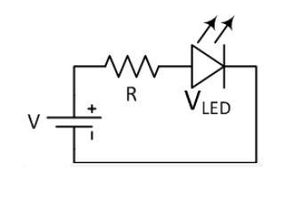
In this example:
- VCC is the power supply (like a 12V battery or adapter)
- The resistor limits the current
- The LED lights up as current flows from positive to ground
In real boards, especially SMD LED PCB boards, this wiring is replaced with copper tracks. The LEDs are surface-mounted, meaning they’re soldered directly on the board. Multiple LEDs can be placed in series, parallel, or a combination, depending on your application.
You’ll also see labels for input voltage, ground, and other components like capacitors, diodes, or voltage regulators if your board is more advanced.
LED Light Circuit Board Design Guide
If you want to design an LED light circuit board for commercial or long-term use, there are a few more things to consider beyond a simple circuit.
1. Choose the LED Type Wisely
Your LED type affects layout, current, and heat. For general lighting, SMD LEDs (such as 2835 or 5050 types) are common. For signage or high-power use, COB LEDs may be better.
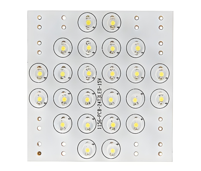
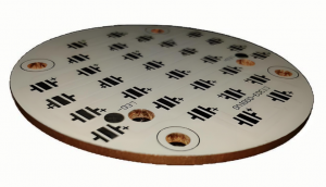
2. Decide on Board Material
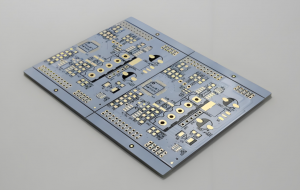
If your LEDs run hot, like in street lights or industrial lights, go for aluminum or metal-core PCBs. These manage heat much better than traditional FR4 boards. Below is a LED pcb board used aluminum base.
3. Include Heat Management
Use thermal vias, heat sinks, or thicker copper layers if the board carries high currents. Heat buildup can shorten LED life or reduce brightness.
4. Control Current
Never rely on direct voltage for LEDs. Use resistors or constant current drivers. LEDs create heat, especially if many are packed closely. Too much heat lowers their lifespan. Good thermal design includes:
- Thick copper layers (≥1oz)
- Thermal vias under LED pads
- Aluminum base to move heat away
- Heat sinks or thermal pads if needed
5. Pay Attention to Trace Width
High currents need wider traces. Use trace calculators to ensure your copper width is suitable. Also, avoid sharp 90° turns—these can stress the signal and cause EMI problems. Use 45° angles to keep signals smooth and reduce heat buildup.
6. Place Components Smartly
Keep resistors close to the LEDs. Separate power and signal lines. Leave space for heat dissipation or mounting. Some other tips including:
- Place resistors near the LED they control
- Keep power and ground lines wide and short
- Group similar LEDs in rows or grids
- Leave space for mounting holes or connectors
- Keep heat-generating parts away from sensitive ones
7. Test Points and Labels
Add test pads for checking voltage and current during production or troubleshooting. Label input/output pads clearly to help during assembly. Here is a guide of how to make LED circuit board.
How Many LED Light Fixtures Can Be on One Circuit?
This question comes up a lot in home lighting and commercial installations. The answer depends on how much power each fixture uses and what the circuit breaker rating is.
Let’s break it down:
- A standard 15A breaker on 120V power provides 1800 watts.
- A 20A breaker gives you 2400 watts.
Suppose each LED fixture consumes 10 watts. Then on a 15A circuit:
1800W / 10W = 180 fixtures
But you should never use 100% of the circuit’s capacity. A safe rule is to use up to 80%.
So, the real number is:
1800W × 0.8 = 1440W → 144 LED fixtures (10W each)
What Happens If You Wire an LED the Wrong Way?
LEDs are diodes, which means they conduct electricity in one direction only. If you connect them backward:
- They won’t light up because current can’t flow
- In some cases, if voltage is too high, the LED might get damaged
This is why LED symbols in diagrams have a direction (anode to cathode). Many modern circuits include a protection diode or a reverse-polarity safeguard to prevent damage.
Always double-check before soldering or applying power. Getting the polarity right is crucial for the LED to work.
Should I Put a Resistor Before an LED?
Yes. A resistor is essential unless you’re using a regulated current driver.
LEDs don’t limit their own current. If you connect them directly to a power supply, even at a “safe” voltage, they can draw too much current, overheat, and burn out.
The resistor acts like a gate. It lets the right amount of current pass through and drops the extra voltage. Even LED strips usually have built-in resistors. For DIY boards, always calculate and add the correct resistor for every LED or LED group.
LED Board Design Price
The LED board design price depends on several factors:
| Factor | Cost Impact |
| Board Size | Larger boards cost more |
| LED Type (SMD vs. COB) | COB boards may be pricier |
| PCB Material (FR4 vs. Aluminum) | Aluminum is more expensive |
| Quantity | Larger batches lower per-board cost |
| Layers | Multilayer boards cost more |
| Assembly Required | Soldered boards cost extra |
Typical costs for LED circuit boards:
- Basic LED board (single-layer FR4): $0.50 – $2 per piece
- Aluminum SMD LED board: $1 – $4 per piece
- Custom-designed and assembled board: $5 – $20 depending on design complexity
For mass production, you can get volume discounts and better pricing through professional LED PCB manufacturers like EBest Circuit (Best Technology). We provide free DFM checks, fast quotes, and one-stop services including prototype to volume production.
FAQs
1. What is a SMD LED PCB board?
It’s a printed circuit board designed to mount Surface-Mounted Device (SMD) LEDs directly onto the board, used in lighting panels, strips, and signs.
2. How long does an LED circuit board last?
With good design and cooling, LED boards can last 30,000 to 50,000 hours or more.
3. Can I connect LEDs in series or parallel?
Yes. Series connections share the same current; parallel connections share the same voltage. Choose based on your power source.
4. What software should I use to design LED boards?
KiCAD, Altium Designer, EasyEDA, and Eagle are commonly used tools for creating LED PCB layouts.
5. What happens if you put too many lights on a circuit?
If you connect too many LED lights to one circuit, the total power draw may exceed the circuit’s capacity. This can lead to overloaded breakers, flickering lights, or even tripped fuses. In worst cases, wires may overheat, posing a fire risk.
If you’re planning to build or order custom LED light circuit boards, EBest Circuit (Best Technology) is ready to help. We support everything from LED PCB board quick-turn prototypes to mass production, all with professional engineering support and strict quality checks.
You may also like


Tags: led board design price, led circuit board diagram, led light circuit board design, smd led pcb board