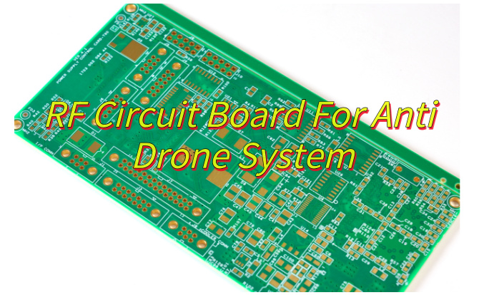
How can RF circuit board revolutionize anti-drone systems with their unique capabilities? This overview explores their design principles, environmental resilience, cost-efficiency, and full-band performance in counter-drone applications.
- How to achieve an effective interference distance of 500 meters with a limited budget?
- How to avoid signal interference causing false alarms from communication base stations?
- Can it be compatible with mainstream drone frequency bands without interfering with GPS?
EBest Circuit (Best Technology) Can Provide You:
- Stepped power enhancement service: Dynamic impedance matching technology improves antenna efficiency, and actual measurements show that it can extend the effective interference distance by 15%.
- Base station signal collaborative analysis service: Adaptive notch filter is used to achieve 20ms-level rapid response to sudden base station signals.
- Multi-protocol compatible solution: GPS L1 band out-of-band suppression reaches 55dB, and millimeter-level frequency band isolation is achieved through cavity filters.
Welcome to contact us if you have any request for RF circuit boards: sales@bestpcbs.com.
What Is A RF Circuit Board?
A RF circuit board is a specially engineered printed circuit board designed to transmit, receive, and process high-frequency radio signals, typically from a few megahertz (MHz) into the gigahertz (GHz) range and beyond. Unlike standard PCBs handling lower frequencies or digital signals, these boards require exceptional attention to signal behavior at high speeds.
They utilize specialized dielectric materials, such as PTFE (Teflon) or ceramic-filled laminates, chosen for stable electrical properties and minimal signal loss at RF frequencies. Precise control over trace geometries, impedance matching, grounding structures (like coplanar waveguides), and shielding techniques are fundamental. This careful design minimizes signal distortion, power loss (insertion loss), and unwanted radiation (EMI), ensuring signal integrity is maintained throughout the circuit path. RF circuit boards are essential components in wireless communication devices, radar systems, satellite technology, and high-speed test equipment.

Benefits of RF Circuit Boards
- Superior High-Frequency Handlingâ: RF circuit boards maintain signal quality across wireless frequencies from mobile networks to satellite communications, preventing degradation.
- Precision Signal Managementâ: Advanced designs minimize interference between components, ensuring stable connections in crowded electronic environments.
- Temperature-Resistant Operationâ: Specialized materials prevent performance fluctuations during extended use or in extreme conditions.
- Space-Efficient Architectureâ: Multi-layer construction allows complex circuitry in compact devices like wearables and IoT sensors.
- Enhanced Durabilityâ: Manufactured to withstand environmental stressors including moisture, vibration, and thermal cycling.
- Application-Specific Customizationâ: Engineers can optimize designs for particular frequency ranges, power requirements, and physical constraints.
- Energy-Efficient Performanceâ: Optimized signal pathways reduce power waste, extending battery life in portable electronics.

Application of RF Circuit Board
- 5G RF Boards â Enable low-latency millimeter-wave data transfer in urban networks.
- Medical RF Systems â Process high-precision signals for MRI/radiotherapy with thermal stability.
- Automotive Radar Modules â Support 77 GHz collision detection and adaptive cruise control.
- Satellite RF Components â Manage X/Ka-band signals for GPS and Earth observation in space.
- IoT RF Connectivity â Provide Bluetooth/Wi-Fi links in smart devices with compact, low-power designs.
- Military RF Tech â Jam signals and analyze spectrums with EMI-shielded high-power amplifiers.
- Industrial RF Control â Enable wireless robot/AGV operation via interference-resistant frequency-hopping.
- Consumer Electronics RF â Integrate cellular/Wi-Fi/GPS in smartphones with miniaturized, high-efficiency layouts.
How to Design RF Circuit Boards for Anti-Drone Jamming Systems?
RF Circuit Board Design Process for Anti-Drone Jamming Systems:
1. Architectural Design
- Split into transmit (TX) and receive (RX) modules.
- Map RF signal flow from amplifiers to antennas.
2. Component Selection
- Amplifiers: GaN transistors (2â6 GHz) with OIP3 > 45 dBm.
- Filters: Cavity filters (TX) and SAW filters (RX).
- Antennas: Directional patch arrays (â¥15 dBi gain) with circular polarization.
3. PCB Layout
- Layer Stackup: 6-layer board with RF layers between ground planes.
- Impedance Control: 50 Ω microstrip traces (Er = 3.5â4.5).
- Isolation: Separate TX/RX sections by â¥50 mm; use via fences (20 mils diameter).
4. Power & Thermal Design
- Power: DC-DC converters (â¥90% efficiency); twisted-pair cables.
- Thermal: Aluminum heat sinks with thermal epoxy; NTC thermistors.
5. Signal Integrity & EMC
- Routing: High-power traces â¥3à wider than low-level signals.
- Shielding: Aluminum enclosures with EMI gaskets; stitched vias.
- Grounding: Star topology; M3 screws for chassis-to-board grounding.
6. Prototyping
- Fabricate 4-layer board with tunable component footprints.
- Include SMA connectors for temporary testing.
7. Validation
- Lab Testing: Measure power, harmonics, and EVM using VNA.
- Field Testing: Deploy in open areas; monitor interference with spectrum analyzers.

How to Ensure Extreme Environmental Reliability in Anti-Drone RF Boards?
Optimized Strategies for Extreme Environmental Reliability in Anti-Drone RF Boards:
Robust Material Selection
- Use high-Tg laminates (e.g., PTFE, ceramic-filled hydrocarbons) for substrates to resist thermal deformation.
- Apply thick copper traces (â¥2 oz) to minimize resistive losses under temperature extremes.
Advanced Thermal Management
- Integrate thermal vias (12 mils diameter, 8 mils spacing) under power amplifiers to transfer heat to ground planes.
- Attach aluminum/copper heat sinks with phase-change materials (PCMs) for low-resistance bonding.
- Include Peltier modules or fans for forced-air cooling in enclosed systems.
Environmental Sealing
- Apply conformal coatings (acrylic, silicone, or parylene, 25â50 µm) to protect against moisture and chemicals.
- Encapsulate critical components in epoxy/urethane potting for shock and vibration resistance.
- Use silicone/EPDM gaskets around connectors for IP67/IP68 compliance.
Vibration and Shock Mitigation
- Replace rigid connectors with flexible PCBs or shielded cables to absorb mechanical stress.
- Secure heavy components with epoxy adhesive or locking screws.
- Attach boards to chassis using rubber or spring-loaded standoffs for vibration damping.
Corrosion and Humidity Control
- Apply ENIG or OSP finishes to pads and vias for corrosion resistance.
- Use sacrificial zinc coatings on metal enclosures in salt-fog environments.
- Include desiccant packets inside sealed enclosures to manage humidity.
Extreme Temperature Adaptation
- Select components rated for -55°C to +125°C operation (capacitors, resistors, inductors).
- Use Sn-Bi or Sn-Ag-Cu solder alloys (melting point <140°C) to prevent cold-environment cracking.
EMI/EMC Hardening
- Enclose RF sections in nickel-silver or copper shields with EMI gaskets.
- Add feedthrough capacitors and ferrite beads to power lines for noise suppression.
- Implement single-point grounding for analog and digital sections to avoid loops.

Cost-Effective RF Circuit Board Solutions for Anti-Drone System
Component Standardization
- Use COTS amplifiers/filters (e.g., 2.4 GHz/5.8 GHz modules) to eliminate custom development costs.
- Replace discrete components with integrated front-end modules (amplifier + filter combinations).
Material Optimization
- Use FR-4 substrates for non-RF sections (e.g., control logic) to cut material expenses by 30â50%.
- Reserve PTFE/ceramic laminates only for high-frequency traces (e.g., antenna feeds).
Simplified Layer Stackup
- Design 4-layer boards (signal-ground-power-ground) instead of 6-layer.
- Avoid blind/buried vias; use through-hole vias with staggered patterns for cost efficiency.
Automated Testing
- Develop in-house test jigs (e.g., Arduino-based power meters) for basic checks (output power, harmonics).
- Replace expensive spectrum analyzers with open-source tools (e.g., GNU Radio scripts) for signal validation.
Design Reuse
- Create modular sub-boards (e.g., 2.4 GHz power amplifier module) repurposable across systems.
- Standardize connectors (e.g., U.FL for RF, JST for power) to simplify inventory and repairs.
Thermal Management Trade-offs
- Replace active cooling (fans, Peltier modules) with passive solutions (aluminum heat sinks + thermal pads).
- Use stamped aluminum enclosures instead of machined magnesium for 40â60% cost reduction.
Regulatory Compliance
- Pre-certify designs for unlicensed bands (e.g., 2.4 GHz Wi-Fi) to avoid redesign costs.
- Use pre-compliance tools (e.g., USB spectrum analyzers with EMI filters) before formal testing.
Lifecycle Cost Reduction
- Design for field repairability (socketed amplifiers, plug-in filters) to extend device lifespan.
- Update firmware via USB/SD cards instead of hardware recalls (50â70% savings per update).
Why Choose EBest Circuit (Best Technology) as Your RF Board Manufacturer?
- High-Frequency Precision Manufacturing â With ±0.025mm drilling accuracy and impedance control within 1%, we solve signal integrity issues in 5G/mmWave designs, backed by 67GHz testing.
- Material & Process Expertise â 50+ qualified laminates (including ultra-low-loss Rogers/Duroid) and strict tan δ (<0.0015) control ensure consistent RF performance.
- Thermal Reliability Solutions â Metal-core boards and embedded heat pipes (15W/cm² dissipation) prevent warping/delamination in high-power applications.
- Rapid Prototyping & NPI Support â 24 hours prototype turnaround with DFM feedback within 4 hours accelerates your development cycle.
- Supply Chain Security â 12-month buffer stock of critical materials and AS9100 logistics eliminate production delays.
- Dedicated Engineering Partnership â Each project gets a senior RF engineer for real-time technical support from design to volume production.
Can RF Boards Overcome Full-Band Scanning Failures?
Yes, RF boards can overcome full-band scanning failures through design optimizations, signal processing, and environmental hardening. These strategies ensure reliable spectrum analysis even in noisy or dynamic conditions.
Signal Integrity Focus
- Use impedance-matched microstrip lines (50 Ω ±5%) and via stitching to minimize signal loss, ensuring weak frequencies are detected during scans.
- Integrate bandpass filters (e.g., SAW) to suppress out-of-band interference, improving signal clarity.
Dynamic Range Management
- Deploy low-noise amplifiers (LNAs) with <1 dB noise figures to amplify faint signals without distortion.
- Add automatic gain control (AGC) to adjust amplification levels dynamically, preventing saturation from strong nearby signals.
Redundant Scanning Paths
- Design multi-channel architectures (e.g., dual independent receivers) to cross-validate results, reducing false negatives from single-channel issues.
- Use RF switches to reroute signals to backup channels if anomalies are detected, ensuring continuous scanning.
Environmental Stability
- Include temperature sensors and bias-adjustment circuits to stabilize amplifier performance across -40°C to +85°C, avoiding thermal drift.
- Shield sensitive components (e.g., LNAs) with nickel-silver enclosures and EMI gaskets to block external interference.
Adaptive Software Tools
- Embed self-calibration routines (e.g., frequency sweeps) to compensate for component aging or manufacturing variances.
- Use FPGA-based processing to adjust scan parameters (dwell time, step size) in real time based on environmental feedback
By combining these approaches, RF boards deliver robust full-band scanning capabilities, making them reliable for anti-drone systems, spectrum monitoring, and wireless security applications.
Tags: RF Circuit Board, RF PCB


