

From charging phones to transferring data between devices, USB (Universal Serial Bus) has become one of the most familiar interfaces in electronics everywhere. Universal Serial Bus (USB) is everywhere. But while everyone uses USB daily, few people know how it actually works or how each pin functions inside the connector.
Understanding USB pinout is essential for engineers, PCB designers, and anyone who deals with cable repair or prototyping. Whether you’re working with USB-A, USB-B, or the modern USB-C, knowing each pin’s purpose helps you connect devices safely and efficiently. This guide explains every detail of USB pinouts — including female and male connectors, wire color codes, data transfer principles, and what happens when connections go wrong.
What Is the Pinout for USB?
The USB pinout defines the electrical layout and functionality of the connector’s pins. Each pin has a specific role, such as carrying power, transferring data, or grounding the circuit.
Different types of USB connectors — USB Type-A, USB Type-B, Micro-USB, and USB-C — share similar core principles but have different numbers of pins.
Here’s a simple overview of common USB versions:
- USB 1.1 / 2.0: 4 pins (Power, Ground, and two data lines)
- USB 3.0 / 3.1: 9 pins (adds extra SuperSpeed data pairs)
- USB-C: 24 pins (supports data, power delivery, and video output)
In short, the pinout structure defines how the USB communicates and delivers power between devices.
USB Pinout Diagram
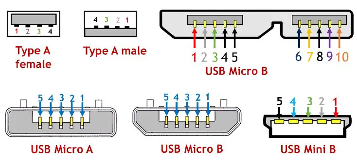
The usb pinout male connector (the plug) is typically what you insert into a device or computer port, while the usb pinout female connector (the receptacle) is what’s mounted on the board or device side.
USB 2.0 Type-A (Male Plug)
| Pin | Name | Wire Color | Description |
| 1 | VBUS | Red | +5V Power |
| 2 | D– | White | Data – |
| 3 | D+ | Green | Data + |
| 4 | GND | Black | Ground |
This is the standard configuration used in most USB pinout male connectors. The female connector (socket) has the same pins but in reverse order, facing inward.
USB 3.0/3.1 Type-A (Male Plug)
| Pin | Name | Wire Color | Description |
| 1 | VBUS | Red | +5V Power |
| 2 | D– | White | Data – |
| 3 | D+ | Green | Data + |
| 4 | GND | Black | Ground |
| 5 | StdA_SSRX– | Blue | SuperSpeed Receive – |
| 6 | StdA_SSRX+ | Yellow | SuperSpeed Receive + |
| 7 | GND_DRAIN | Black | Ground |
| 8 | StdA_SSTX– | Purple | SuperSpeed Transmit – |
| 9 | StdA_SSTX+ | Orange | SuperSpeed Transmit + |
The extra pins in USB 3.0 and newer allow for faster data rates and improved power management.
USB-C Pinout
The USB-C pinout is the most advanced. It’s symmetrical, meaning you can plug it in either way.
| Pin | Name | Description |
| A1, B1 | GND | Ground |
| A4, B4 | VBUS | +5V Power |
| A5, B5 | CC | Configuration Channel |
| A6, B6 | D+ | USB 2.0 Data + |
| A7, B7 | D– | USB 2.0 Data – |
| A8, B8 | SBU1/SBU2 | Sideband Use |
| A9, B9 | VBUS | +5V Power |
| A12, B12 | GND | Ground |
| A2–A3, B10–B11 | TX/RX | High-Speed Data Lanes |
USB-C connectors can handle much higher power, up to 100W, and transfer data at speeds exceeding 20 Gbps.
USB Pinout Color Code
The usb pinout color code helps you identify wires easily when stripping or repairing cables. The colors are mostly standardized:
| Color | Signal | Description |
| Red | VBUS | +5V Power |
| White | D– | Data – |
| Green | D+ | Data + |
| Black | GND | Ground |
| Blue/Yellow | SuperSpeed RX/TX (USB 3.x) | High-speed data lanes |
Always double-check with a multimeter before soldering or reconnecting wires. While most cables follow this color code, some low-cost ones might differ slightly.
How to Identify USB Pins?
Identifying pins is easier than it looks. Start by checking the USB symbol on the connector to find its orientation. Then, look inside — you’ll see four or more contact pads.
For a USB pinout female port:
- Pin 1 (VBUS) is usually on the left if the port’s wider side faces up.
- Pin 4 (GND) sits on the far right.
For a USB pinout male plug:
- Pin 1 (VBUS) is on the right when the flat side faces down.
- Pin 4 (GND) is on the left.
Using a simple continuity test can also help confirm which pin connects to which wire. It’s especially useful when building custom USB cables or integrating USB interfaces on PCB designs.
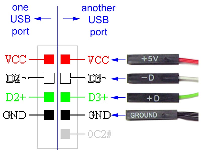
Which USB Pin Is Power and Ground?
Power delivery is one of USB’s fundamental functions. The power (VBUS) and ground (GND) pins form the electrical foundation for charging and powering devices.
- Pin 1 (Red): +5V DC (VBUS) — supplies power to the connected device.
- Pin 4 (Black): Ground (GND) — provides the return path for current.
In older USB versions (1.1 and 2.0), this voltage is fixed at 5V, typically providing up to 500mA of current.
With USB 3.0 and later, the current increases to 900mA, while USB-C supports adjustable power delivery (PD) up to 20V and 5A (100W) depending on negotiation between devices.
If you ever test a USB cable with a multimeter, the red wire corresponds to the +5V pin, and the black one connects to ground.
USB Data Transfer
USB communication happens over differential pairs, meaning the D+ (green) and D– (white) lines carry complementary signals. This design minimizes interference and enables stable, high-speed data transfer. Here’s how data transfer works:
1. The host (computer or controller) initiates communication.
2. The D+ and D– lines transmit binary data in opposite polarity.
3. The device responds through the same lines, completing two-way communication.
USB 2.0 supports up to 480 Mbps, while USB 3.0/3.1 adds new data pairs (SuperSpeed lines) to reach 5 Gbps and 10 Gbps, respectively. USB-C goes even further — supporting USB 4.0 and Thunderbolt modes with speeds over 40 Gbps, depending on configuration.
What Do the Red, White, and Green Wires Do in a USB Cable?
Every wire inside a USB cable plays a unique role:
- Red (VBUS): Supplies +5V DC power to charge or operate the device.
- White (D–): Carries the negative side of the differential data signal.
- Green (D+): Carries the positive side of the differential data signal.
- Black (GND): Provides the common return path for current.
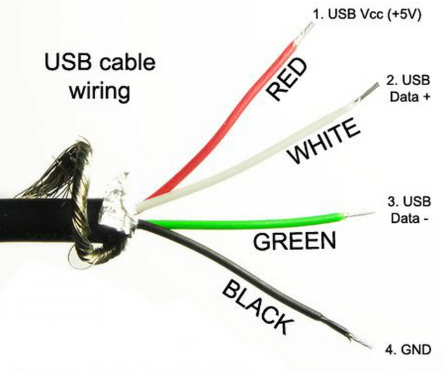
If one of these connections is interrupted — for example, a broken white or green wire — the USB will still supply power but won’t transfer data properly. This explains why some damaged cables “charge only” but fail to sync data.
Which USB Wires Are Positive and Negative?
In USB wiring:
- Positive: Red wire (VBUS) — supplies +5V.
- Negative: Black wire (GND) — completes the electrical circuit.
The data pair (white and green) also has positive and negative roles:
- D+ (green) carries positive data signals.
- D– (white) carries negative data signals.
This differential system is key for stable and interference-free communication. Always double-check wire polarity before soldering or connecting to avoid damage.
What Happens If I Mix Up Positive and Negative Wires?
Mixing up positive and negative USB wires can damage your devices or ports. If you accidentally reverse them, the circuit might short, causing immediate disconnection or, in worst cases, permanent hardware damage.
- The USB port may short-circuit, triggering protection or permanently damaging components.
- Devices could fail to boot or suffer electrical damage.
- PCB traces might burn due to excessive current.
For this reason, always double-check the pinout before soldering or applying power. Using fuses or protection circuits in prototypes is also a wise practice.
What Happens If You Plug a USB 2.0 into a USB 3.1 Port?
The good news — USB standards are backward compatible. Plugging a USB 2.0 cable or device into a USB 3.1 port will still work safely.
However, data speed will be limited to the lowest standard in the connection. For example, if you connect a USB 2.0 flash drive to a USB 3.1 port, the data rate caps at 480 Mbps instead of 10 Gbps.
Compatibility is one of USB’s greatest strengths — you can mix different generations without damaging your devices.
USB-C Pinout Overview
The usb-c pinout is far more advanced than earlier types. With 24 symmetrical pins, USB-C supports reversible plug orientation, fast data transfer, and powerful charging options.
Here’s a simplified overview of the USB-C pin configuration:
| Pin Group | Function | Description |
| A1–A4, B1–B4 | VBUS | Power delivery (5V–20V) |
| A5, B5 | CC1, CC2 | Configuration channels (detect orientation & role) |
| A6–A7, B6–B7 | D+, D– | USB 2.0 data lines |
| A8–A11, B8–B11 | TX/RX Pairs | SuperSpeed differential pairs |
| A12, B12 | GND | Ground lines |
| SBU1, SBU2 | Sideband Use | Alternate functions (DisplayPort, audio, etc.) |
Because USB-C is reversible, you can insert it in either direction — the system automatically recognizes the orientation through CC1 and CC2 pins. It also supports Power Delivery (PD), allowing dynamic voltage adjustment from 5V to 20V, making it suitable for charging laptops, monitors, and industrial equipment.
Why Partner with EBest Circuit (Best Technology) for USB-Related PCB Projects?
When it comes to USB-based PCB design, precision and reliability matter. EBest Circuit (Best Technology) is a trusted PCB manufacturer specializing in custom circuit boards and assemblies that integrate USB power and communication circuits.
We provide:
- Comprehensive engineering support for USB-A, USB-B, Micro-USB, and USB-C connectors
- High-quality PCB fabrication with strict impedance control for data traces
- ISO-certified quality systems, including ISO9001, ISO13485, IATF16949, and AS9100D
- Full traceability system to monitor production and ensure full transparency
- Prototype to mass production services, covering cable integration, connector soldering, and testing
- Factory based price with no minimum quantity order requirements
Whether you need usb-c pinout-based designs for fast-charging products or usb pinout male/female connectors for embedded systems, EBest Circuit (Best Technology) offers professional solutions tailored to your application
FAQs About USB Pinout
1. What is the difference between USB 2.0, 3.0, and USB-C pinouts?
USB 2.0 has 4 pins—power, ground, and two data lines. USB 3.0 adds five extra pins to support faster data rates up to 5 Gbps. USB-C is more advanced, with 24 pins supporting reversible connections, higher current (up to 5A), and protocols like DisplayPort and Thunderbolt.
2. Can I connect USB male and female cables with different pinouts?
Yes, but only if the pin assignments match. For example, connecting a USB 2.0 male to a USB 3.0 female works because USB 3.0 ports are backward compatible. However, improper wiring or mismatched pinouts may cause unstable connections or charging failure.
3. Why are USB wires color-coded?
The color codes make identification simple during repair or assembly. Red is usually +5V (VCC), black is ground (GND), white is data– (D–), and green is data+ (D+). These color standards help avoid short circuits or reversed connections.
4. Can I use USB pins to power other devices?
Yes, but with caution. Standard USB 2.0 provides up to 500mA, while USB 3.0 can supply 900mA. USB-C supports higher power levels up to 100W (20V/5A) under the Power Delivery (PD) standard. Always check the device’s power requirements before using USB pins as a power source.
5. What should I do if my USB cable gets hot or doesn’t charge properly?
Overheating may indicate a short circuit, incorrect wiring, or poor cable quality. Disconnect it immediately and inspect the pinout. Using cables with the correct gauge and verified USB certification ensures both safety and performance.
Tags: usb pinout, usb pinout color code, usb pinout female, usb pinout male