

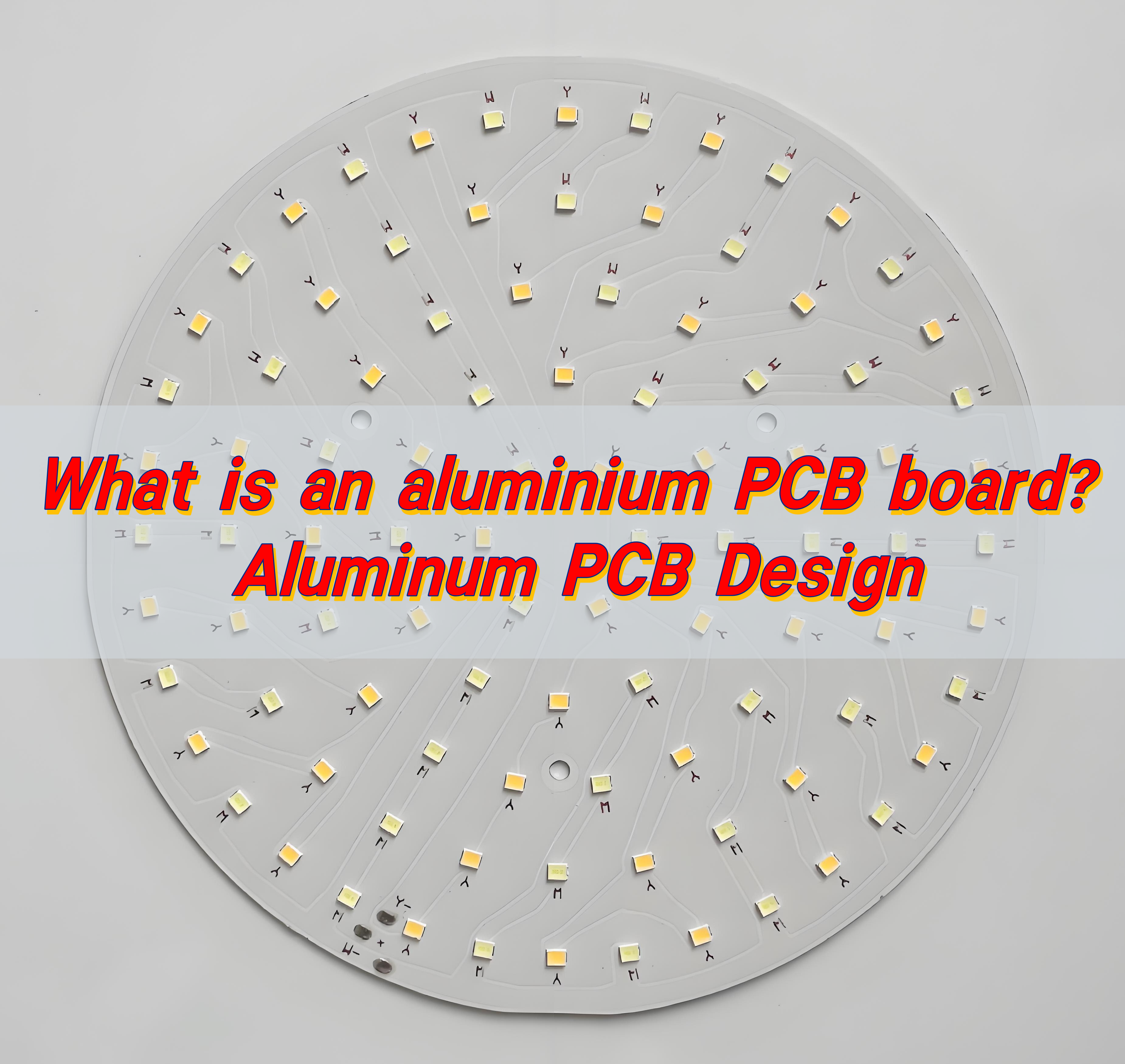
Aluminium PCB boards are metal-based printed circuit boards with an aluminum alloy substrate. Their thermal conductivity is dozens of times higher than that of traditional FR-4, allowing them to quickly dissipate heat from chips and prevent failures caused by hot spots. Combined with highly reflective white oil and a thin insulating layer, they serve as both a circuit and a heat sink, making them widely used in LED lamps, power modules, and automotive electronics.
How to make aluminium PCB board?
Making an aluminium PCB board involves precision and the right materials. It starts with choosing a quality aluminium substrate. It’s then coated with an insulating dielectric layer, which isolates the conductive copper from the metal.
Next comes copper lamination. A thin sheet of copper is pressed onto the dielectric surface. This copper layer will form the circuit paths. Once laminated, the board is cleaned and coated with a photoresist. Ultraviolet (UV) light exposure follows, using a circuit design mask to harden certain parts of the photoresist.
Unexposed areas are washed away, revealing the pattern. The exposed copper is then etched off, leaving behind the circuit layout. After this, any remaining photoresist is stripped. Now the board is cleaned and goes through a surface finish process, such as HASL or ENIG, depending on the end-use.
Finally, the board is cut into shape and tested for functionality. Every step is crucial for ensuring electrical performance and heat resistance.
How does the aluminium PCB manufacturing process work?
The aluminium PCB manufacturing process includes several refined steps to deliver a high-quality board. Here is a simplified overview:
- Material preparation: Choose an aluminium base, usually with a thickness of 0.8mm to 3.0mm. Apply a thermal insulation layer and copper foil.
- Lamination: Bond the dielectric and copper layers tightly to the aluminium. Heat and pressure ensure this bond holds firm.
- Imaging: Apply a photoresist film and expose the board under UV light. The light hardens the areas forming the copper traces.
- Etching: Remove unwanted copper using chemical solutions. Only the protected areas from imaging remain.
- Drilling and Plating: Drill precise holes for component leads or vias. Plate these holes if needed.
- Solder Mask and Surface Finish: Apply a protective solder mask to non-conductive areas. Add a surface finish to enhance solderability and corrosion resistance.
- Testing: Perform electrical tests to check for shorts, open circuits, and reliability.
- Profiling: Cut the board to the desired size and shape.
These steps are controlled tightly. That’s why working with an experienced aluminium PCB manufacturer is critical.
How to design an efficient aluminum PCB?
Designing an effective aluminium PCB starts with understanding its strengths. Heat management is the top reason to use aluminium. Start by placing high-power components closer to the metal core. This reduces thermal buildup.
Keep trace lengths short and direct. This minimizes resistance and power loss. Use wider traces for higher current paths. Layer stack-up also matters. A single-layer design is often enough for LED and power circuits. For more complex boards, consider a multilayer design.
Thermal vias can help in spreading heat, especially in multilayer boards. Select the right thickness for your dielectric layer to ensure proper insulation and heat flow.
When choosing the surface finish, think about the end application. ENIG works well for fine-pitch components. HASL is good for general use.
Excellent aluminum PCB design balances electrical, mechanical, and thermal performance. Choose BEST Technology, you will get the best aluminum PCB design
What are the layers of aluminum PCB?
Aluminium PCB boards generally have three layers:
- Aluminium Base Layer: This is the mechanical support and heat conductor. It’s usually made of alloy 5052 or 6061 for strength and heat resistance.
- Dielectric Layer: Placed between the base and copper foil. This insulation layer resists heat and electrically isolates the copper traces. Thickness varies from 50µm to 200µm.
- Copper Layer: This is the conductive layer where the circuit forms. Thickness can range from 1oz to 3oz depending on current requirements.
Some designs include additional layers:
- Solder Mask: Applied over the copper to prevent oxidation and short circuits.
- Silkscreen: For labeling component placements and orientation.
These layers combine to offer durability, high thermal conductivity, and efficient current flow in one compact board.
What is the highest temperature aluminum PCB can withstand?
Aluminium PCBs are built to handle high heat. Their metal base and insulating layer offer much better thermal management than standard FR4 boards. Depending on the material used, aluminium PCBs can endure temperatures between 120°C to 150°C continuously.
For short durations or pulse heating, they can handle spikes up to 250°C. Some high-grade aluminium PCBs, with advanced dielectric materials, may go even higher.
This heat resistance makes them ideal for LED lighting, automotive controls, and power converters. Proper design and material selection can ensure your board works reliably in high-heat environments.
Can aluminum PCB support high frequency signals?
Yes, aluminium PCB boards can support high frequency signals. But it depends on the quality of the dielectric layer. A low-loss dielectric material ensures signal stability.
In high-frequency applications, such as communication devices and radar systems, signal integrity is crucial. Aluminium PCBs with high-performance dielectric can deliver clear, uninterrupted signals.
Design also plays a role. Keep signal paths short and separate analog from digital traces. Ground planes and impedance control improve performance even more.
Though aluminium PCBs aren’t the first choice for all RF applications, they work well in many mid-frequency designs.
How strong is FR4 compared to aluminum?
FR4 is the standard fiberglass material used in many PCBs. It’s lightweight, low-cost, and electrically reliable. But when it comes to strength and heat resistance, aluminium is superior.
Aluminium offers better mechanical support. It doesn’t warp under heat like FR4. It also dissipates heat much faster, which is vital in LED or power circuits.
FR4 works well for multi-layer signal processing boards. But for durability, thermal control, and stability, aluminium PCBs outperform FR4 in harsh conditions.
So, if your project demands strength and heat resistance, aluminium PCB is the better choice.
How does aluminum PCB compare to rigid flex and HDI PCB?
Aluminium PCBs, rigid flex PCBs, and HDI PCBs each serve different needs.
- Aluminium PCB: Best for heat-intensive applications. Offers strong thermal management and mechanical strength.
- Rigid Flex PCB: Combines flexibility and rigidity. Perfect for compact devices with moving parts like cameras or foldable screens.
- HDI PCB: Designed for high-density circuits with microvias. Used in smartphones, tablets, and miniaturized electronics.
If your design demands heat dissipation and durability, aluminium wins. If space-saving and flexibility are key, go with rigid flex. For high-speed, high-density circuits, HDI is the way to go.
Conclusion:
Aluminium PCB boards are powerful and reliable. In many cases, they outperform traditional solutions in terms of heat dissipation and mechanical strength. Whether you’re working on LED lighting, power electronics, or high-frequency devices, Aluminium PCB boards provide a solid foundation.
Choose a professional partner to get the best results. At EBest Circuit (Best Technology), we specialize in high-quality aluminium PCB boards with custom design support and fast delivery.
Reach out to us today at sales@bestpcbs.com
Tags: aluminium board price, aluminium pcb board, aluminium pcb board for led, aluminum board price, aluminum pcb board, aluminum pcb design