In PCB layout design, routing angles have a direct impact on signal integrity, manufacturing quality, and overall board performance. The two most common routing angles—45-degree and 90-degree—have long been debated among engineers and designers. While both have their uses, the choice between them depends on electrical performance, fabrication processes, and design goals.
This blog explores the differences between 45-degree and 90-degree routing angles. We’ll break down how each angle affects your board’s reliability, signal flow, and manufacturability. You’ll also get practical insights into when and why to choose one over the other.
Why Routing Angles Matter in PCB Design?
Routing angles may seem like a minor detail, but they carry more weight than you might expect. When copper traces change direction sharply, it impacts how current flows through the circuit. This is especially critical for high-speed and high-frequency designs. Uneven trace transitions can cause reflections, impedance discontinuity, and even signal degradation.
Aside from performance, routing angles influence how easy it is to manufacture, etch, and inspect the board. Smooth routing not only helps the signals but also improves the final product’s consistency and durability.
What Is a 90-Degree Routing Angle?
A 90-degree angle in PCB routing refers to a sharp right-angle corner where a trace takes a turn. It is often called a right-angle bend and used mostly in older or simpler PCB layouts.
Characteristics:
- Easy to draw and route.
- Common in low-frequency, analog, or single-layer PCBs.
- Produces a clear, angular look on CAD tools.
Despite its simplicity, the 90-degree bend has downsides when it comes to electrical performance and manufacturing precision, which we’ll explore in detail later.
What Is a 45-Degree Routing Angle?
A 45-degree angle is a more gradual, beveled bend in PCB traces. Instead of a sharp corner, the trace changes direction at an angle, forming a smoother path. Some layouts even use two 45-degree bends to make a soft curve.
Characteristics:
- Smoother current flow.
- Reduced signal reflection.
- Preferred for high-speed and high-frequency circuits.
Many modern CAD tools default to 45-degree routing due to its positive effect on signal integrity and trace etching quality.
Main Differences Between 45-Degree and 90-Degree Angles
| Feature | 45-Degree Angle | 90-Degree Angle |
| Signal Integrity | Better, due to smooth transitions | Worse, due to corner reflections |
| EMI/EMC | Lower emissions | Higher emissions |
| Manufacturing | Easier to etch; fewer defects | Etch traps can form at corners |
| Trace Length | Slightly longer | Shorter, more direct |
| CAD Complexity | Slightly harder to route manually | Very easy to route |
| Aesthetic & Professionalism | Industry standard for high-speed | Looks dated in modern designs |
Why 90-Degree Angles Can Be a Problem?
1. Impedance Discontinuity
Sharp corners create impedance mismatches that disrupt uniform signal travel. This is especially noticeable in controlled impedance traces, where precision is key. Signal reflection at a 90-degree turn can distort waveforms and cause errors in communication lines.
2. Electromagnetic Interference (EMI)
A sharp angle acts like a small antenna. This increases electromagnetic emissions, which may lead to your product failing EMI compliance tests. It also raises the risk of cross-talk in dense layouts.
3. Etching Defects
During fabrication, etching around a sharp 90-degree corner can cause acid traps, where chemical etchants get stuck and over-etch the copper. This can weaken the trace or cause open circuits.
4. Signal Reflection
Right-angle bends can cause signal reflection and ringing, particularly at high frequencies. This distorts the signal waveform and affects timing, which is critical in fast digital or RF systems.
Why 45-Degree Routing Is Widely Used?
The use of 45-degree routing in PCB design has become a standard practice in the industry. While older layouts sometimes featured sharp 90-degree angles for simplicity, most modern PCB designs now adopt 45-degree bends. Below are the key factors that explain why 45-degree routing is widely used.
1. Smoother Signal Transitions
In high-speed PCB designs, signal integrity is everything. Signals travel along copper traces like waves, and any abrupt direction change can reflect or distort the waveform. A 90-degree corner creates a sudden path change, which introduces a small but sharp discontinuity.
2. Lower Electromagnetic Interference (EMI)
Electromagnetic interference (EMI) is a growing concern in today’s electronics, especially in wireless and communication systems. Sharp trace corners such as 90-degree bends tend to behave like antennas. They concentrate electric fields and can emit higher levels of radiation, contributing to EMI. Designs that follow 45-degree routing are more likely to pass EMI compliance tests and meet international standards for electromagnetic compatibility.
3. Improved Manufacturability
From a manufacturing point of view, sharp corners can introduce several problems. During the etching process, chemical etchants used to remove unwanted copper may get trapped in 90-degree corners. These are known as acid traps. They can lead to over-etching, where too much copper is removed, or even undercutting, which weakens the trace at the bend.
4. Better Heat Distribution
Although routing angles don’t directly affect thermal conductivity, trace shapes can influence heat flow, especially in power boards. Smooth traces, like those formed with 45-degree bends, allow more even heat distribution along the path. Sharp corners may act as stress points where heat can build up, potentially weakening the copper over time.
5. Supports High-Speed and RF Design Standards
High-speed digital and RF designs demand strict control over trace geometry, impedance, and layout structure. In such designs, even minor trace irregularities can lead to signal degradation, noise coupling, or timing issues. Most high-speed PCB design guidelines—such as those for DDR memory, USB 3.0, HDMI, or RF transceivers—explicitly discourage the use of 90-degree angles.
How to Avoid 90-Degree Angles in PCB Design?
Most PCB layout software supports angle snapping, which makes it easy to design 45-degree routes. Here are a few tips:
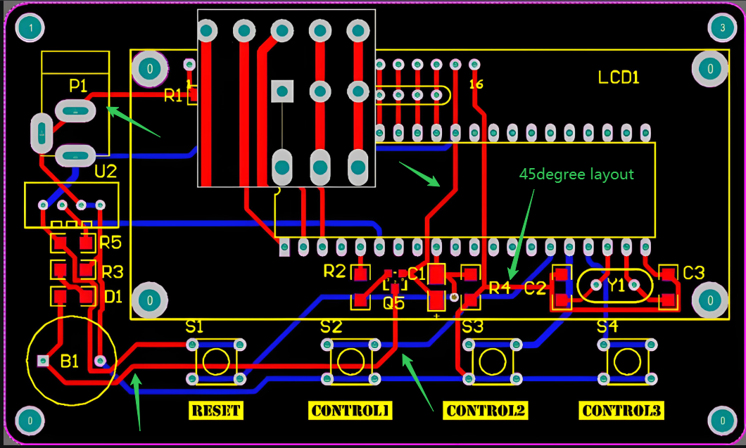
- Use 45-degree snap mode in your routing tool.
- Use arc routing for smoother transitions in sensitive areas.
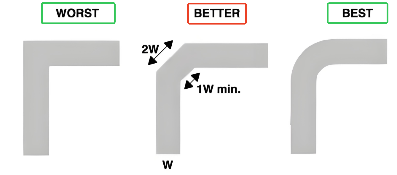
- Double-bend technique: Instead of a single 90-degree, use two 45-degree bends to redirect the trace.
Check your DRC (Design Rule Check) for right-angle warnings if available.
PCB CAD Tools That Help With Angle Rules
| CAD Software | Routing Features |
| Altium Designer | 45-degree snap, arc routing, right-angle DRC checks |
| KiCad | Push-and-shove routing with 45-degree control |
| EAGLE | Adjustable angle routing; user can disable 90-degree |
| OrCAD | Precision routing tools for high-speed design |
| EasyEDA | Snap-to-45 built-in, ideal for quick layouts |
Industry Standards and Best Practices
Several industry guidelines recommend using 45-degree angles, especially for high-speed circuits. Some key takeaways:
- IPC standards encourage smooth trace transitions.
- Many RF and microwave design rules prohibit 90-degree bends.
- Professional board reviewers often flag right angles as poor practice.
Following these standards doesn’t just improve performance—it also gives clients and manufacturers confidence in your designs.
Common Myths About Routing Angles
Myth 1: 90-Degree Bends Always Break the Signal
Not always. If you’re working with low-speed signals or power lines, the impact is negligible. The problem grows with frequency, edge rate, and sensitive signals.
Myth 2: 45-Degree Routing Takes More Space
It may take a tiny bit more space, but not enough to justify poor signal integrity. Most modern designs can accommodate 45-degree bends with minor effort.
Myth 3: 90-Degree Angles Are Cheaper to Fabricate
Not true. They can actually increase manufacturing costs due to over-etch risks or inspection failures.
Why Choose Best Technology for PCB Design and Manufacturing?
At Best Technology, we go beyond just making PCBs. We help you design better boards from the start. Whether you’re routing high-speed digital signals or managing dense analog layouts, our engineering team follows best practices—including angle rules—to improve your product’s performance.
We are certified under ISO9001, ISO13485, IATF16949, and AS9100D, with an MES system that ensures traceability and quality control. We specialize in both standard and complex PCB manufacturing, including HDI, RF, and metal-core designs.
Contact Us Today
If you need help with routing strategy or want high-quality PCB production, our team is ready. From prototype to volume production, we can support your needs with fast delivery, quality control, and engineering guidance.
📩 Reach out now to get your quote and talk to our experts.
FAQs
1. Do 90-degree angles always cause EMI issues?
Not always. At low frequencies, the impact is minimal. But in high-speed or RF designs, they can be problematic.
2. Is 45-degree routing mandatory for all traces?
It’s not mandatory, but it’s highly recommended for signal traces, especially in complex or fast designs.
3. Can I use rounded corners instead of 45-degree angles?
Yes. Rounded corners are even better for very high-speed signals but may increase layout complexity.
4. Are 90-degree bends allowed in power planes?
Yes. Since power planes don’t carry high-speed signals, 90-degree turns are generally safe there.
5. How can I check for right angles in my layout?
Use your PCB tool’s DRC (Design Rule Check) to scan for sharp angles or manual review if needed.