





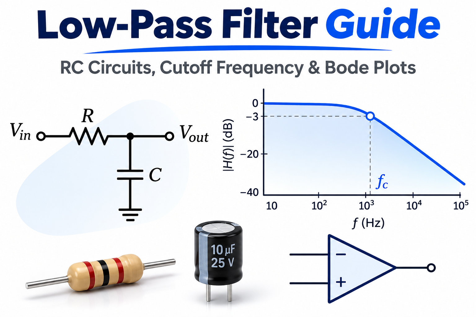
A low-pass filter (LPF) passes signals below a selected cutoff frequency while attenuating higher-frequency components. It is commonly used to remove electrical noise, smooth sensor outputs, reduce PWM ripple, and condition audio signals. Low-pass filters can be built using resistor-capacitor (RC) networks, inductor-capacitor (LC) circuits, operational amplifiers, or digital signal processing. This guide explains how to calculate cutoff frequency, read Bode plots, understand transfer functions, and design RC, Butterworth, and Sallen-Key filters for practical electronic applications.
At EBest Circuit, we provide PCB fabrication, component sourcing, SMT/DIP assembly, and functional testing for analog and mixed-signal circuits. Our Free DFM, No MOQ, 4 SMT lines, and MES single-board traceability support projects from engineering prototypes to repeat production. Each project is coordinated by 1 sales representative and 3 engineers who can review component footprints, BOM accuracy, assembly requirements, and customer-defined test specifications. Send your Gerber files, BOM, quantities, and filter requirements to sales@bestpcbs.com for a manufacturing review and quotation.
Key Takeaways
- A low-pass filter passes low-frequency signals and attenuates high-frequency components. The attenuation increases progressively rather than stopping signals abruptly at the cutoff frequency.
- A first-order RC low-pass filter uses a series resistor and a capacitor connected from the output to the reference node. Its response depends on the resistance and capacitance values.
- The cutoff frequency of an ideal RC filter is calculated from resistance and capacitance. A 10 kΩ resistor combined with a 10 nF capacitor produces approximately 1.59 kHz.
- At the −3 dB cutoff frequency, the output voltage amplitude is approximately 70.7% of its passband value. This corresponds to a 50% power ratio for equal impedances.
- A first-order low-pass filter approaches −20 dB/decade attenuation above cutoff, while a second-order filter approaches −40 dB/decade.
- Passive RC and LC filters require no active amplification. Active filters use devices such as operational amplifiers to provide buffering, gain, or higher-order frequency responses.
- Butterworth is a maximally flat magnitude response, while Sallen-Key is an active filter topology. A Sallen-Key circuit can be designed to achieve a Butterworth response.
- Actual low-pass filter performance depends on component tolerances, source and load impedances, op amp specifications, PCB layout, and testing conditions.
What Is a Low-Pass Filter and What Does It Do?
A low-pass filter is a circuit that preserves lower-frequency signals while reducing higher-frequency signals. Its main purpose is to separate useful low-frequency information from unwanted high-frequency components.
A typical low-pass filter response contains 3 regions:
- Passband: Frequencies that pass with relatively little attenuation.
- Transition Band: The region where attenuation increases.
- Stopband: Frequencies that experience substantial attenuation.
For example, a temperature sensor may produce a slowly changing voltage mixed with high-frequency noise from nearby digital circuits. A low-pass filter can suppress that noise while preserving the sensor’s slower voltage changes.
Low-pass filters are commonly used in sensor conditioning, audio systems, PWM smoothing, power-supply filtering, and ADC input circuits. The required cutoff frequency and attenuation depend on the useful signal bandwidth and the amount of unwanted noise.
How Does an RC Low-Pass Filter Circuit Work?
An RC low-pass filter uses a resistor in series with the input and a capacitor connected between the output and the signal reference. The output is measured across the capacitor. As input frequency increases, the capacitor’s reactance decreases, causing greater attenuation of high-frequency signals.
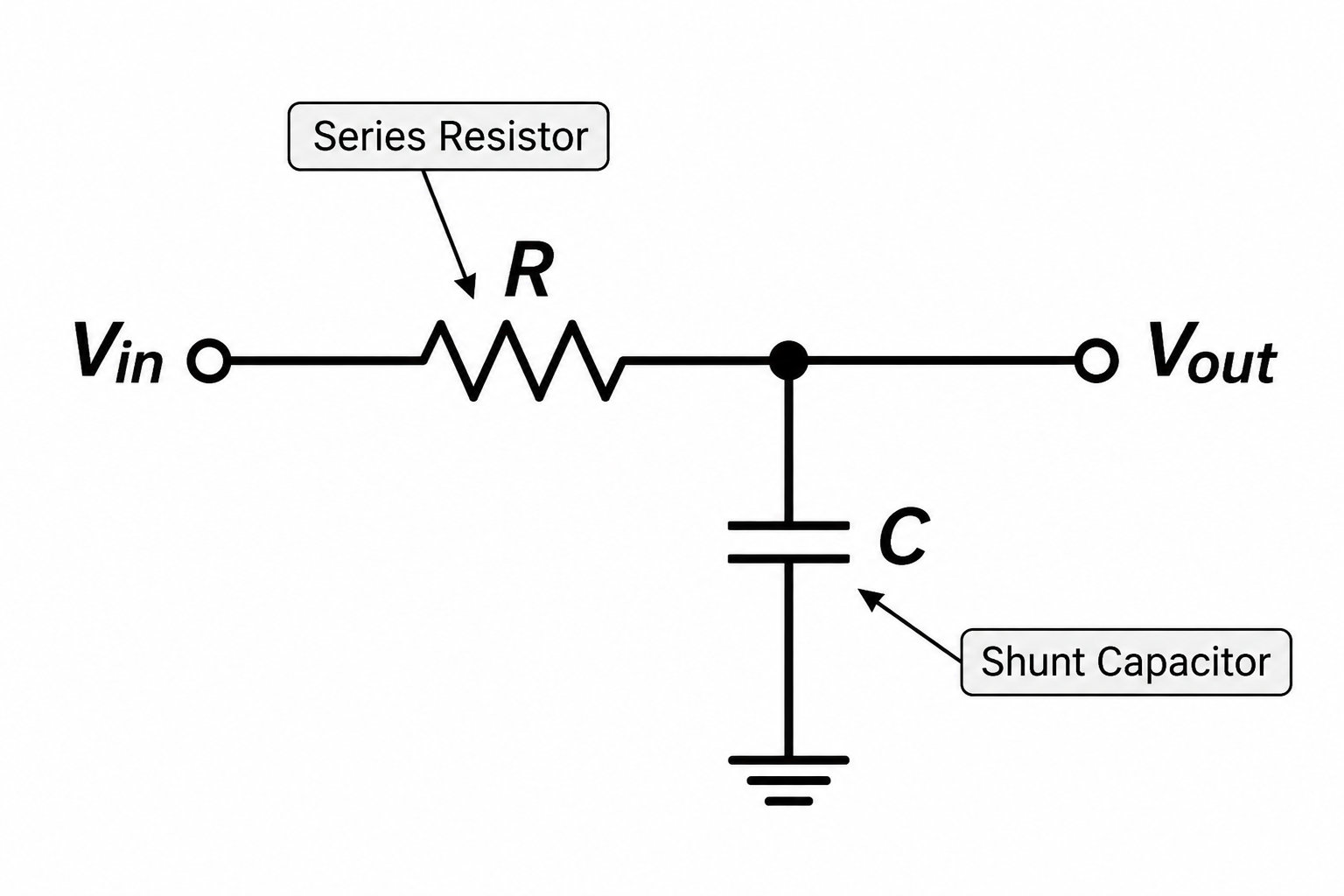
1. Resistor Function
The resistor limits current flowing into and out of the capacitor, helping determine how quickly the output responds to voltage changes. Increasing resistance lowers the cutoff frequency when capacitance remains constant.
2. Capacitor Function
The capacitor provides frequency-dependent impedance. Its capacitive reactance is:
At low frequencies, the capacitor presents relatively high impedance, allowing the output to follow the input. At higher frequencies, its impedance falls and more signal current flows toward the reference node, reducing the output amplitude.
3. RC Time Constant
The time constant determines the circuit’s transient response:
For a 10 kΩ resistor and 10 nF capacitor:
During an ideal step response, the output reaches approximately 63.2% of its final change after 1 time constant and 99.3% after 5 time constants. This relationship is useful when a filter must reduce noise without excessively slowing the response of a sensor or control signal.
How Do You Calculate the Cutoff Frequency of an RC Low-Pass Filter?
The cutoff frequency of an ideal first-order RC low-pass filter is calculated from its resistance and capacitance. Increasing either value lowers the cutoff frequency, while decreasing either value raises it.
The standard formula is:
- fc: Cutoff frequency (Hz).
- R: Resistance (Ω).
- C: Capacitance (F).
1. RC Cutoff Frequency Calculation
Consider a circuit with the following components:
| Parameter | Value |
|---|---|
| Resistance | 10 kΩ |
| Capacitance | 10 nF |
| Target | Calculate cutoff |
Convert the values into base units:
Substituting into the cutoff equation gives:
The calculated cutoff frequency is approximately 1.59 kHz.
2. Calculate Resistance for a Target Frequency
If the target cutoff frequency is known, rearrange the formula:
For a 1 kHz cutoff using a 10 nF capacitor:
A standard 16 kΩ resistor gives a calculated cutoff frequency of approximately 995 Hz, close to the 1 kHz target.
3. RC Low-Pass Filter Calculator
4. How Does Component Tolerance Affect Cutoff Frequency?
Actual resistors and capacitors vary from their nominal values. For small changes, the approximate relationship is:
For example, a ±1% resistor and ±5% capacitor give a first-order worst-case cutoff variation of approximately ±6%. More accurate limits can be calculated from the extreme component values. For production designs, engineers should also review capacitor temperature characteristics, DC-bias behavior, and the impedance of connected circuits.
What Is the Transfer Function of a Low-Pass Filter?
The transfer function describes how a low-pass filter changes signal amplitude and phase with frequency. For an ideal first-order RC circuit, it is determined by the resistor-capacitor time constant.
The transfer function is:
Here, s is the complex frequency variable. The product RC determines the pole location and therefore the frequency response.
1. Magnitude Response
For sinusoidal steady-state analysis, substitute s = jω:
The magnitude is:
This expression shows how the output amplitude decreases as frequency rises.
2. Phase Response
The phase angle is:
- Well below cutoff: phase approaches 0°.
- At cutoff: phase equals −45°.
- Well above cutoff: phase approaches −90°.
These equations assume ideal components and negligible loading. Source resistance, load impedance, and component parasitics can change the measured response.
How Do You Read a Low-Pass Filter Bode Plot?
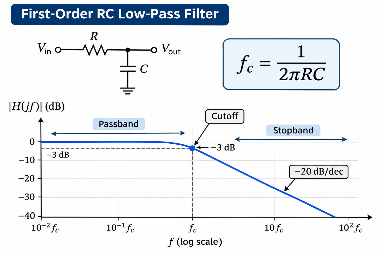
A low-pass filter Bode plot shows signal attenuation and phase shift across frequency. The magnitude plot identifies the passband, −3 dB cutoff frequency, and stopband attenuation, while the phase plot describes the frequency-dependent phase lag.
For the 10 kΩ and 10 nF RC example, the calculated cutoff frequency is approximately 1.59 kHz.
1. The −3 dB Cutoff Point
At cutoff, the voltage amplitude ratio is:
This means the output voltage amplitude is about 70.7% of its passband value. The corresponding power ratio is 50% when the comparison uses the same impedance.
2. Roll-Off Slope
- First-order filter: Approaches −20 dB/decade.
- Second-order filter: Approaches −40 dB/decade.
- Fourth-order filter: Approaches −80 dB/decade.
These are asymptotic slopes. The actual attenuation near cutoff depends on the filter response and quality factor.
3. RC Frequency Response Example
| Frequency | Gain |
|---|---|
| 100 Hz | −0.02 dB |
| 1 kHz | −1.45 dB |
| 1.59 kHz | −3.01 dB |
| 10 kHz | −16.07 dB |
| 100 kHz | −35.96 dB |
Engineers can generate these curves using SPICE, MATLAB, or Python. Laboratory measurements with a function generator and oscilloscope or frequency-response analyzer can verify the assembled PCB.
What Are the Main Types of Low-Pass Filter Circuits?
The main low-pass filter implementations are passive RC, passive LC, active analog, and digital filters. The appropriate type depends on frequency range, source and load impedance, required attenuation, and available power.
| Filter Type | Components | Typical Use |
|---|---|---|
| RC Passive | Resistor + capacitor | Sensor filtering |
| LC Passive | Inductor + capacitor | Power and RF |
| Active | Op amp + R/C | Analog conditioning |
| Digital | DSP / MCU | Sampled data |
1. Passive RC Low-Pass Filter
An RC filter is compact, inexpensive, and suitable for low-power analog signals. It requires no external power for the filter network, although its response may change when connected to a low-impedance load.
2. Passive LC Low-Pass Filter
An LC filter uses inductors and capacitors to attenuate unwanted frequencies. It is common in power-supply output filtering, RF circuits, and applications where resistive losses must be limited. Important design considerations include inductor saturation, winding resistance, capacitor ESR, and possible resonance.
3. Active Low-Pass Filter
An active low-pass filter uses an amplifier together with resistors and capacitors. It can provide buffering, gain, or a higher-order response without large inductors. The op amp must have sufficient bandwidth, suitable input/output voltage ranges, and acceptable noise and distortion characteristics.
4. Digital Low-Pass Filter
A digital low-pass filter processes sampled data using numerical calculations. It offers programmable cutoff frequencies and filter characteristics, but introduces requirements for sampling rate, processing resources, numerical precision, and latency.
What Is a Butterworth Low-Pass Filter?
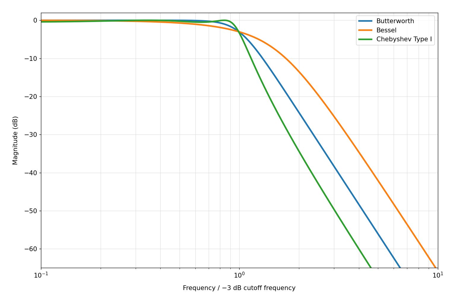
A Butterworth low-pass filter provides a maximally flat magnitude response in the passband, without passband ripple. It is useful when a smooth amplitude response is more important than achieving the steepest possible transition between passed and attenuated frequencies.
Butterworth describes a frequency-response characteristic, not a specific component arrangement.
| Response Type | Main Characteristic |
|---|---|
| Butterworth | Maximally flat passband |
| Bessel | Favorable group-delay behavior |
| Chebyshev Type I | Sharper transition with ripple |
1. Butterworth Response
For a normalized second-order Butterworth low-pass filter, the quality factor is:
This value produces the desired second-order Butterworth response, with its −3 dB point at the natural frequency.
2. Filter Order and Attenuation
For an nth-order all-pole low-pass filter, the asymptotic stopband slope is:
For example, a fourth-order Butterworth filter approaches −80 dB/decade above its cutoff region. Higher-order filters achieve stronger rejection but require additional components and more careful tolerance control.
3. Typical Applications
- General analog signal conditioning.
- Audio frequency filtering.
- Instrumentation circuits.
- Applications requiring a flat passband.
When preserving waveform timing or transient shape is more important than magnitude flatness, a Bessel response may be more suitable.
How Does a Second-Order Sallen-Key Low-Pass Filter Work?
A second-order Sallen-Key low-pass filter uses 2 resistors, 2 capacitors, and an operational amplifier to create a second-order frequency response. The RC network sets the filter poles, while the op amp provides buffering or non-inverting gain.
Sallen-Key is a circuit topology. Butterworth is a response target that the topology can achieve with suitable component values.
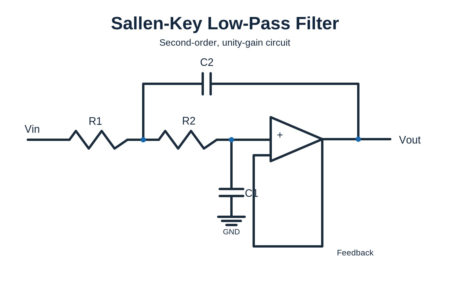
1. Main Circuit Components
- R1 and R2: Frequency-setting resistors.
- C1 and C2: Frequency-setting capacitors.
- Operational amplifier: Provides buffering or non-inverting gain.
- Reference voltage: Establishes appropriate signal bias for the supply arrangement.
These components work together to produce a two-pole low-pass response.
2. Second-Order Transfer Function
A common second-order low-pass transfer function is:
- K: Passband gain.
- ω₀: Natural angular frequency.
- Q: Quality factor.
- s: Complex frequency variable.
The natural frequency is:
For a second-order Butterworth response, Q is approximately 0.707, making the natural frequency equal to the −3 dB cutoff frequency.
3. Example: 10 kHz Sallen-Key Filter
Texas Instruments provides a second-order Butterworth Sallen-Key reference design with these target specifications:
| Parameter | Value |
|---|---|
| Supply Voltage | 5 V |
| Signal Reference | 2.5 V |
| Cutoff Frequency | 10 kHz |
| Passband Gain | 1 V/V |
| Response | Butterworth |
The 2.5 V reference provides the DC bias needed for the single-supply analog signal path. The component values and op amp characteristics are chosen to achieve the intended frequency response.
Before assembling a Sallen-Key filter, check the resistor and capacitor tolerances, op amp gain-bandwidth product, input/output voltage limits, and output loading. Changes in component ratios can affect both cutoff frequency and Q.
Reference: Texas Instruments Sallen-Key Low-Pass Filter Design.
How Do You Design and Test a Low-Pass Filter PCB?
Designing a low-pass filter PCB requires defining the frequency response, selecting suitable components, preserving signal integrity during layout, and measuring the finished circuit. The manufactured board should be evaluated against the same electrical conditions used during design.
1. Define the Electrical Requirements
Start with measurable specifications:
- Cutoff frequency: For example, 1 kHz or 10 kHz.
- Passband gain: Such as unity gain.
- Stopband attenuation: Required rejection at a specified frequency.
- Input signal range: Minimum and maximum amplitude.
- Supply voltage: Available operating rails.
- Source and load impedance: Conditions affecting filter response.
These requirements determine whether a simple RC network is adequate or a higher-order active filter is needed.
2. Select Components
Resistors and capacitors should be selected according to their electrical characteristics, not only nominal values. For resistors, review tolerance, temperature coefficient, and power rating. For capacitors, check capacitance tolerance, dielectric type, rated voltage, temperature behavior, and DC-bias effects.
Active filters also require an op amp with appropriate:
- Gain-bandwidth product.
- Slew rate.
- Input common-mode voltage range.
- Output voltage swing.
- Noise performance.
- Stability under the intended load.
3. Review PCB Layout and Assembly
Analog filters are sensitive to unwanted coupling and parasitic effects. Before production, verify:
- Footprint Mapping: Correct R/C and op amp packages.
- Feedback Placement: Short connections around frequency-setting networks.
- Ground Return: Controlled signal-current return paths.
- Power Decoupling: Capacitors near active devices.
- BOM Accuracy: Approved MPNs and component values.
- Assembly Files: Matching Gerber, BOM, placement, and assembly documentation.
A compact, properly routed circuit helps reduce unwanted parasitic effects and improves repeatability between assemblies.
4. Measure Frequency Response
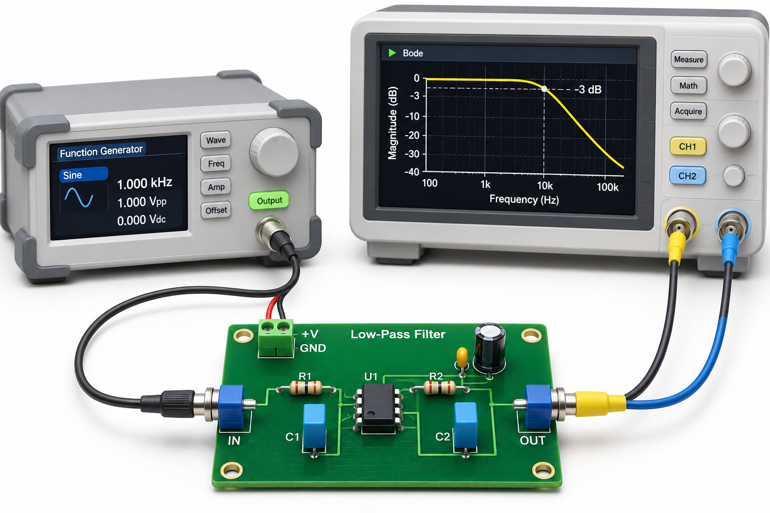
A practical frequency-response test uses a function generator and suitable voltage-measurement equipment. The test process is:
- Apply a known sinusoidal input signal.
- Sweep frequency across the passband and stopband.
- Measure input and output amplitudes.
- Calculate voltage gain.
- Identify the −3 dB cutoff frequency.
- Compare measured attenuation with the design target.
Gain in decibels is calculated using:
If necessary, additional tests can check phase shift, overshoot, settling time, and output noise.
5. Verify Production Consistency
Differences between simulated and measured results may arise from component tolerance, source/load impedance, op amp behavior, or PCB parasitics.
At EBest Circuit, our engineering team can review filter component requirements, BOM data, footprints, assembly constraints, and customer test specifications. Our PCB fabrication, SMT/DIP manufacturing, and inspection capabilities support the complete manufacturing process, while project-specific functional testing helps verify the assembled circuit against the required filter performance.
Low-Pass Filter vs High-Pass Filter: What Is the Difference?
A low-pass filter passes lower frequencies and attenuates higher frequencies, while a high-pass filter passes higher frequencies and attenuates lower frequencies. Both can use RC networks, but the location of the output node determines the basic filtering behavior.
| Feature | Low-Pass Filter | High-Pass Filter |
|---|---|---|
| Passed Frequencies | Low | High |
| Attenuated Frequencies | High | Low |
| Basic RC Output | Across capacitor | Across resistor |
| Typical Application | Noise reduction | DC blocking |
Low-Pass Filter Example
A temperature sensor produces a slowly changing voltage contaminated by high-frequency interference. A low-pass filter reduces the noise while preserving the slower measurement.
High-Pass Filter Example
An audio signal contains an unwanted DC offset. A high-pass filter attenuates the DC component and very low frequencies while passing the useful audio signal. The choice depends on the frequency range containing useful information and the frequencies the circuit needs to reject.
Why Choose EBest Circuit for Low-Pass Filter PCB Manufacturing?
EBest Circuit provides PCB fabrication, component sourcing, SMT/DIP assembly, inspection, and functional testing for analog filter and mixed-signal circuits. With PCB manufacturing and assembly services coordinated through one engineering team, we help customers manage component accuracy, manufacturability, assembly quality, and production requirements.
Our manufacturing capabilities include:
- Free DFM Review: Review PCB stackups, op amp footprints, R/C placement, signal routing, and manufacturability before production.
- No MOQ: Support engineering prototypes, low-volume validation, and repeat production.
- 4 SMT Lines: 2 JUKI and 2 YAMAHA production lines.
- 01005 Assembly: Support miniature components in compact analog circuits.
- PCB Manufacturing: Fabricate FR4, multilayer, HDI, and other circuit boards according to project requirements.
- Component Sourcing: Procure approved resistors, capacitors, inductors, op amps, and supporting components.
- SMT/DIP Assembly: Support passive RC networks, active filter boards, and mixed-technology assemblies.
- Inspection and Testing: SPI, AOI, X-Ray where applicable, ICT, and customer-defined FCT.
- MES Traceability: Board-level manufacturing records.
- Engineering Support: 1 sales representative and 3 engineers coordinating technical reviews and production requirements.
Our manufacturing operations are supported by applicable quality management certifications, including ISO 9001, ISO 13485, IATF 16949, and AS9100D, with certification scope available for supplier qualification.
For an RC low-pass filter PCB, Sallen-Key active filter, sensor conditioning board, audio filter, or complete PCBA project, send your Gerber files, BOM, pick-and-place data, quantities, cutoff frequency targets, and test requirements to sales@bestpcbs.com. Our engineers can review the manufacturing requirements and provide a project-specific quotation.
Frequently Asked Questions About Low-Pass Filters
1. Is a low-pass filter the same as an RC filter?
No. An RC filter is one implementation of a low-pass filter. Low-pass filters can also use inductors and capacitors, operational amplifiers, or digital signal processing. The best implementation depends on the required cutoff frequency, attenuation, signal impedance, and application.
2. Does a low-pass filter completely block high frequencies?
No. A practical low-pass filter progressively attenuates higher-frequency signals rather than blocking them completely at one frequency. A first-order RC filter approaches −20 dB/decade attenuation above cutoff, while higher-order filters can provide steeper rejection.
3. Can I use an LM358 op amp for a low-pass filter?
Yes. An LM358 can be used in suitable low-frequency active filter circuits, including some Sallen-Key designs. Its gain-bandwidth product, slew rate, input common-mode range, output swing, and noise must meet the circuit requirements. Higher-frequency filters may require a faster op amp.
4. What cutoff frequency should I use for a subwoofer?
A subwoofer low-pass cutoff is commonly set around 60–120 Hz, depending on the speaker system and crossover arrangement. The best setting provides a smooth transition between the subwoofer and main speakers without excessive overlap or a frequency-response gap.
5. Can a low-pass filter reduce PWM noise?
Yes. RC and LC low-pass filters can attenuate PWM switching components and produce a smoother output. Ripple reduction improves as the filter attenuates the PWM frequency, but lowering the cutoff also slows the response to changes in duty cycle.
6. Can a low-pass filter prevent aliasing in an ADC?
An analog low-pass filter helps prevent aliasing by attenuating frequencies that would fold into the sampled signal band. The cutoff frequency, transition band, and stopband attenuation must be selected according to the ADC sampling rate and useful signal bandwidth.
7. Does a higher-order low-pass filter always work better?
No. Higher-order filters provide steeper attenuation but also increase component count, sensitivity to tolerances, and design complexity. Phase shift, transient response, noise, and stability may become more important. Choose the lowest filter order that satisfies the required performance.
Conclusion
A low-pass filter is widely used to remove high-frequency noise, smooth analog signals, and prepare signals for audio processing or data acquisition. RC cutoff calculations, transfer functions, and Bode plots help predict frequency response, while Butterworth and Sallen-Key designs provide additional filtering options. Actual performance depends on component values, circuit loading, PCB layout, and testing. EBest Circuit supports low-pass filter projects with Free DFM, No MOQ, PCB fabrication, component sourcing, 4 SMT lines, and functional testing. Send your design files and BOM to sales@bestpcbs.com for an engineering review and manufacturing quotation.
You may also like
Tags: Active Filter Design, Low-Pass Filter, RC Low-Pass Filter