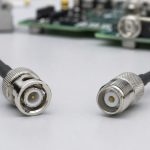
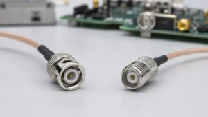
BNC is usually the better choice for fast cable changes, accessible test connections, and 75-ohm video systems, while SMA is usually better when compact size, threaded retention, or higher-frequency performance matters. That quick rule is useful, but it is not enough to specify a connector. The correct choice must also match impedance, cable type, mating frequency, PCB launch geometry, mechanical load, and the performance stated for the exact part number.
An effective BNC vs SMA comparison therefore begins with the whole signal path rather than the connector name alone. A well-rated connector can still perform poorly when it is attached to the wrong cable, launched into an uncontrolled PCB trace, or mixed with an incompatible interface.
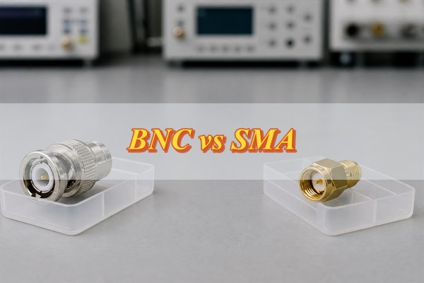
What Are the Core Differences Between BNC and SMA Connectors?
BNC prioritizes quick bayonet coupling, while SMA prioritizes compact size and higher-frequency threaded performance. The table below covers the distinctions that affect specification; the exact ordering code still controls final limits.
| Engineering criterion | BNC | SMA | Selection implication |
| Coupling | Push-and-turn bayonet | 1/4-36 threaded coupling | BNC is faster for frequent access; SMA needs controlled tightening for repeatable contact. |
| Nominal impedance | 50 ohms or 75 ohms, depending on part | 50 ohms | Match source, cable, connector, adapter, PCB trace, and load impedance. |
| Published family range | Standard 50-ohm designs commonly reach DC–4 GHz; qualified extended or 12G-SDI designs can reach DC–12 GHz | Common designs reach DC–18 GHz; precision extended designs can reach 26.5 GHz | Never use the family maximum in place of the exact part-number rating. |
| Panel density | Larger mated interface; standard BNC outer diameter is approximately 14.5 mm | Smaller interface with a 0.312-inch coupling hex commonly used for wrench access | Check connector spacing, finger or wrench clearance, and cable bend radius. |
| Typical mating life | Many qualified product lines specify 500 or more cycles | Common product lines specify up to 500 cycles when correctly torqued | Use the exact mechanical-life specification and inspect frequently serviced ports. |
| Mechanical behavior | Fast positive lock and easy visual confirmation | Threaded retention resists accidental release but can be damaged by cross-threading or over-torque | Support the cable so neither connector transfers bending load into PCB solder joints. |
| Typical best fit | Bench instruments, patching, timing, 50-ohm RF, and 75-ohm video | Compact RF modules, antennas, wireless equipment, and microwave paths | Impedance, frequency, power, environment, and launch geometry decide the final part. |
How Does Operating Frequency Affect the BNC vs SMA Choice?
Use the lowest connector frequency rating in the complete assembly as the real limit. The connector body, cable, adapter, PCB launch, and installation quality form one transmission path. A connector advertised for a high frequency cannot compensate for a poor transition or a lower-rated cable.
Standard BNC products commonly reach 4 GHz, while common SMA products reach 18 GHz and selected designs reach 26.5 GHz. Specialized 75-ohm 12G-SDI BNC products can also reach 12 GHz. These are product-family examples, not automatic ratings for every connector; verify the operating band, VSWR or return loss, and cable combination for the exact part.
Frequency also changes how strongly small discontinuities matter. At higher frequencies, excess center-pin length, a large exposed pad, a gap in the ground return, a via stub, or an abrupt trace-width change can create measurable reflection. The shorter wavelengths make the physical launch geometry electrically larger. This is why an SMA connector may be the right interface yet still fail a return-loss target when its PCB footprint is copied without stackup-specific modeling.
Set the required band before selecting the connector. Include the highest fundamental, required harmonics, modulation bandwidth, and measurement margin. Then compare insertion loss and return loss across that entire band, using the manufacturer’s stated cable, fixture, and reference plane as the qualification boundary.
Should You Choose BNC or SMA for Frequent Connections and Vibration?
Choose BNC when fast, repeated hand connection is the priority; choose SMA when compact threaded retention is more important. A BNC plug can be pushed and locked with a short turn, making it convenient on laboratory instruments and frequently reconfigured test setups. An SMA interface takes longer to mate, but the threaded coupling resists accidental release and fits densely packed equipment.
Neither family is suitable for unlimited mating cycles. Many BNC and SMA product lines specify about 500 cycles, but plating, cleanliness, alignment, and handling determine whether that rating is achieved. For measurement-grade SMA connections, use the part or instrument manufacturer’s torque value; 5 in-lb (56 N-cm) is documented for certain Keysight SMA test interfaces, not as a universal setting.
Design the cable support before approving the connector. A rigid or heavy cable hanging from a board-mounted connector transfers bending force into solder joints, pads, and laminate. Use strain relief, a bulkhead interface, or a supported cable route, then verify shock and vibration qualification for the exact part and intended environment.
Should You Choose 50-Ohm BNC, 75-Ohm BNC, or 50-Ohm SMA?
Use 50-ohm BNC or SMA for a 50-ohm RF path, and use 75-ohm BNC only for a specified 75-ohm system. Fifty-ohm interfaces are standard in RF transmitters, receivers, antennas, test equipment, and many data-conversion systems. Seventy-five-ohm BNC is used in broadcast video and other 75-ohm distribution paths. Standard SMA is a 50-ohm interface.
Mechanical mating does not prove electrical compatibility. Some 50-ohm and 75-ohm BNC products can engage physically, but their internal conductor and dielectric geometry targets different characteristic impedances. Mixing them creates an impedance discontinuity that can increase reflection, disturb amplitude flatness, and reduce measurement accuracy. Confirm cross-mating and contact safety from the exact manufacturers and part numbers, especially when legacy connector designs are involved.
Treat impedance as a BOM-controlled requirement, not a visual choice. A mismatch becomes more damaging as frequency rises, electrical length increases, or the return-loss limit tightens. It might be tolerated in a short, low-frequency monitoring connection, but it can invalidate calibrated RF measurements, broadband digital edges, precision video, or a tuned antenna feed. State the impedance in the schematic, BOM, cable specification, and connector drawing.
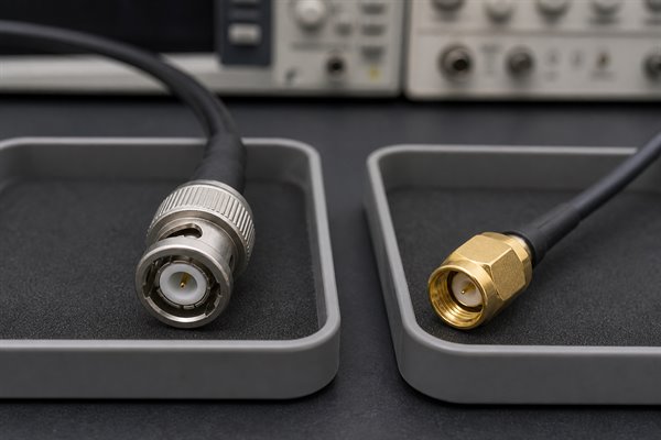
Treat adapters as part of the RF path, not as simple mechanical hardware. A BNC-to-SMA adapter must match nominal impedance and be rated for the required frequency, return loss, insertion loss, power, and gender combination. It cannot exceed the weakest component in the path, and stacked adapters add discontinuities and leverage. Use a direct cable assembly for permanent builds when practical. Also distinguish standard SMA from RP-SMA: the shell gender can look familiar while the center-contact polarity is reversed.
Which BNC or SMA Mounting Style Fits Your PCB?
Select the mounting style from mechanical access, signal-launch direction, enclosure geometry, and expected cable load. Common options include edge-mount, through-hole, surface-mount, vertical, right-angle, and bulkhead connectors. Each style changes the RF transition and the way force enters the board.
| Mounting style | Useful when | Main check |
| Edge-mount | The connector exits directly from the board edge | Board thickness and coplanar launch geometry |
| Vertical PCB mount | The cable approaches perpendicular to the board | Height, keepout, and mechanical leverage |
| Right-angle PCB mount | The cable must run parallel to the board | Internal transition and enclosure clearance |
| Through-hole | Mechanical anchoring is important | Hole tolerance, solder access, and ground pins |
| Surface-mount | Automated assembly and compact layout are needed | Pad design, coplanarity, and strain relief |
| Bulkhead or panel mount | The enclosure should carry cable force | Panel thickness and cable-to-PCB connection |
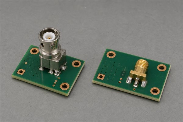
For an edge-mount SMA, confirm the permitted PCB thickness and whether the footprint expects grounded coplanar waveguide, microstrip, or another structure. The connector’s ground tabs must sit against the intended copper surfaces without forcing the center pin out of alignment. For a BNC attached to a PCB, its larger body and cable leverage often justify through-hole ground legs, enclosure support, or a panel-mounted arrangement.
Orientation also affects serviceability. A right angle PCB arrangement can reduce enclosure height, but it needs tool access, cable bend clearance, and a keepout that prevents neighboring parts from blocking the coupling. Review the 3D envelope and mating motion, not only the land pattern.
How Should a BNC or SMA PCB Launch and Ground Return Be Designed?
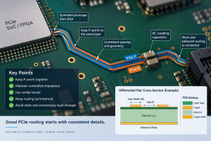
Design the connector launch as a controlled-impedance transition, not as an ordinary component pad. The connector, pad, trace, ground structure, vias, solder, and production stackup form one RF discontinuity. Use the following checks before releasing the footprint:
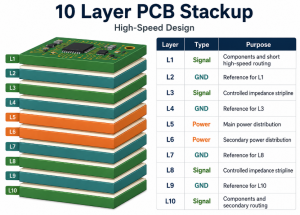
- Start from the production stackup: Use the actual dielectric thickness, Dk value, copper thickness, finished board thickness, solder-mask condition, and target impedance. Calculate or model the trace width and ground gap for the selected microstrip or grounded-coplanar geometry.
- Control the center-pin transition: Keep the exposed pin and signal-pad length short, avoid abrupt trace-width changes, and align the pin without forcing it. An oversized pad adds capacitance; a narrow neck, long pin, or excessive gap adds inductance.
- Provide a short ground-return path: Connect the connector ground tabs or body to continuous ground copper close to the signal transition. Add symmetric stitching vias near the launch so return current does not detour around a void or distant via fence.
- Protect the reference plane: Do not place plane splits, unrelated traces, large antipads, or unnecessary voids beneath the launch. If the signal changes layers, place return vias beside the signal via and reduce or remove the signal-via stub where bandwidth requires it.
- Model the assembled geometry: Include connector body clearance, pad and antipad dimensions, solder-mask opening, finished solder volume, board-edge tolerance, and the manufacturer’s recommended footprint. These details can shift local impedance after assembly.
- Verify before production release: For high-frequency or strict return-loss targets, tune the launch with a field solver or 3D electromagnetic model, then measure a representative coupon or prototype with suitable calibration and de-embedding. Release controlled dimensions, tolerances, and assembly requirements with the footprint.
What Should You Check in a BNC or SMA Connector Datasheet?
Approve the exact ordering code only after its electrical, mechanical, assembly, and environmental limits all match the design. A family name alone cannot establish cable compatibility, PCB geometry, sealing, or RF performance.
| Datasheet area | What to verify | Approval rule |
| Interface identity | BNC or SMA; plug or jack; standard or reverse polarity; 50-ohm or 75-ohm impedance | Approve only when the complete interface designation matches the mating part and system impedance. |
| Qualified RF band | Maximum frequency; VSWR or return loss across the required band; stated cable, fixture, and reference plane | The exact part must meet the reflection target across the full operating band, not only at one frequency. |
| Loss, voltage, and power | Insertion loss; working and dielectric-withstanding voltage; current where specified; power derating versus frequency, temperature, altitude, and mismatch | Approve only with operating margin under the worst specified electrical and environmental condition. |
| Cable termination | Approved cable group; center-conductor, dielectric, and jacket diameters; ferrule; strip dimensions; crimp or solder tooling | Every cable dimension and assembly tool must match the connector manufacturer’s qualified termination method. |
| PCB compatibility | Finished board thickness; footprint revision; center-pin position; ground-tab geometry; orientation; coplanarity; soldering method; keepout | The drawing and land pattern must match the production stackup, enclosure, assembly process, and RF launch design. |
| Mechanical service | Mating-cycle rating; coupling torque; panel thickness; mounting hardware; wrench or finger clearance; cable bend radius; strain relief | The installation must meet service-life needs without transferring cable or coupling force into PCB solder joints. |
| Materials and environment | Contact and body plating; insulator; temperature range; sealing condition; corrosion; vibration; shock; moisture; material compliance | Environmental ratings are acceptable only under the manufacturer’s stated mated, sealed, or capped condition. |
| Procurement control | Manufacturer; full ordering code; drawing revision; approved tooling; inspection requirements; permitted alternates | Lock the approved configuration in the BOM and compare every substitute field by field before release. |
Which Applications Are Better Suited to BNC or SMA?
Choose by operating conditions, not by application name alone. The matrix below identifies the interface that normally gives the best starting point and the condition that can overturn that choice.
| Application condition | Preferred starting point | Engineering reason | Mandatory verification |
| Frequently reconfigured bench instrument or test lead | BNC | Fast bayonet coupling and easy hand access | Confirm 50-ohm input, bandwidth, mating life, and cable strain relief. |
| Broadcast, SDI, CCTV, or video distribution | 75-ohm BNC | Maintains the intended 75-ohm video path and supports secure patching | Confirm the required SDI data rate, connector/cable bandwidth, and return loss. |
| Compact wireless, GPS, antenna, or RF module | SMA or RP-SMA as specified | Small threaded interface suits dense 50-ohm RF assemblies | Verify polarity, frequency, antenna power, enclosure clearance, and cable bend radius. |
| Microwave measurement or high-frequency prototype | SMA only when the exact part covers the band | Greater frequency headroom than standard BNC | Check connector grade, torque, launch model, calibration plane, and full-band return loss. |
| High-vibration or cable-loaded enclosure | Panel-mounted BNC or mechanically supported SMA | The enclosure or support must carry cable force instead of PCB joints | Verify shock/vibration qualification, fastener retention, cable support, and solder-joint load. |
| High-power transmitter path | Do not decide from BNC versus SMA alone | Power may be limited by voltage, heating, mismatch, altitude, and cable loss | Use exact derated power data; select a larger RF interface when margin is inadequate. |
| Permanent BNC-to-SMA transition | Direct 50-ohm cable assembly preferred | Fewer interfaces reduce reflection, loss, and mechanical leverage | Verify impedance, frequency, VSWR, insertion loss, power, and gender. |
Recheck the decision after the enclosure and PCB launch are defined. Identify system impedance, full operating band, allowable reflection and loss, power and voltage, environmental exposure, mating frequency, panel space, and mechanical support. Then verify every requirement against the exact part datasheet. This second BNC vs SMA review prevents an initially sensible family choice from failing at the cable, adapter, or board transition.
FAQs About BNC vs SMA Connectors
Q1: Are SMA and coax the same?
A1: No. Coax describes a cable or transmission structure with concentric conductors. SMA is one connector interface used to terminate certain 50-ohm coaxial cables or connect a coaxial path to a PCB.
Q2: Are SMA and 3.5 mm connectors the same?
A2: No. They are different precision levels and have different frequency capability, although properly made versions are mechanically mateable under defined conditions. Inspect interfaces carefully because damaged or out-of-tolerance connectors can harm expensive test ports.
Q3: Are all SMA connectors compatible?
A3: No. Standard SMA and RP-SMA differ in center-contact polarity. Parts also vary by plug or jack, cable group, mounting style, frequency rating, and environmental design.
Q4: How much power can an SMA connector handle?
A4: There is no single universal value. Power capability depends on the exact part, frequency, VSWR, cable, temperature, altitude, and installation. Use the manufacturer’s derated power data for the specified operating conditions.
Q5: Does connector plating affect RF performance and service life?
A5: Yes, especially at the contact surfaces. Plating affects contact resistance, corrosion behavior, wear, solderability, and mating durability. Compare the specified material, plating system, and thickness for the exact part rather than treating all gold- or nickel-colored connectors as equivalent.
Q6: Can a BNC cable carry audio?
A6: Yes, if the equipment is designed for it. BNC is a connector interface and coaxial cable can carry analog or digital audio signals, but impedance, signal level, grounding, and equipment compatibility still have to match.
Q7: Can two BNC cables be connected?
A7: Yes, with the correct BNC adapter. Match 50-ohm or 75-ohm impedance and understand that the added junction introduces another discontinuity and contact pair. For permanent installations, one correctly sized cable is usually preferable.
Q8: Is BNC better than RCA?
A8: It depends on the system. BNC provides a locking connection and controlled-impedance options, which are valuable in RF, test, and professional video equipment. RCA remains common in consumer audio and video where those characteristics may not be required.
Q9: Why can SMA cable assemblies cost more?
A9: Higher-frequency performance requires tighter control. Precision dimensions, plating, cable preparation, assembly tooling, inspection, and RF testing can increase cost. Price still varies widely with cable type, frequency rating, volume, and qualification.
Q10: Is an unmated BNC or SMA connector weatherproof?
A10: Usually not unless the datasheet explicitly says so. An IP or environmental rating may apply only when the connector is correctly mated, torqued, sealed, or fitted with an approved cap. Verify the exact sealing condition before outdoor use.
Conclusion
BNC and SMA solve different interface priorities. BNC favors quick access, robust hand operation, and both 50-ohm and 75-ohm applications. SMA favors compact threaded retention and greater high-frequency headroom in a 50-ohm system. The final result still depends on the exact connector, cable, PCB launch, mechanical support, soldering quality, and operating environment.
Turn the connector choice into a reliable assembled product. EBest can review your RF footprint and controlled-impedance stackup, manufacture the PCB, source specified connectors, assemble the PCBA, and support inspection and electrical test requirements. Send your Gerber files, BOM, stackup targets, connector part numbers, and test requirements to sales@bestpcbs.com for a PCBA manufacturing review and quotation.
You may also like


Tags: bnc connector, bnc sma pcb, bnc vs sma, SMA Connector