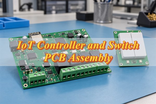
IoT controller and switch PCB assembly requires reliable switching circuits, wireless communication, and stable power management. These assemblies are widely used in smart switches, relay controllers, lighting systems, and industrial control equipment. Manufacturing quality depends on component accuracy, SMT/THT soldering, electrical isolation, and functional testing.
EBest Circuit provides turnkey IoT controller and switch PCB assembly services, covering PCB fabrication, component sourcing, SMT/THT assembly, inspection, and testing support. From prototypes to volume production, we help OEM customers reduce manufacturing risks, simplify supplier coordination, and maintain consistent assembly quality.
What Does Turnkey IoT Controller and Switch PCB Assembly Include?
Turnkey IoT controller and switch PCB assembly combines PCB manufacturing, component procurement, assembly, and agreed testing within one coordinated production service. Instead of managing separate PCB and component suppliers, customers can work with one manufacturing partner using their approved production files.
EBest Circuit supports different sourcing arrangements:
| Service Option | Scope of Service | Suitable For |
|---|---|---|
| Full Turnkey PCBA | PCB fabrication, approved component sourcing, SMT/THT assembly, inspection, and agreed testing | OEM customers seeking one manufacturing partner |
| Partial Turnkey PCBA | EBest sources selected components while customers supply designated parts | Projects using customer-controlled MCUs, relays, or wireless modules |
| Consigned PCB Assembly | Customers supply the required components, with PCB fabrication and assembly arranged according to the order | Projects with established component supply channels |
Firmware programming, custom test fixtures, and additional product integration can be included when agreed during project review.
Turnkey manufacturing begins with customer-approved PCB and assembly data. EBest provides DFM guidance and manufacturing review rather than original circuit design.
What Types of IoT Controllers and Smart Switches Need Custom PCB Assembly?
Custom IoT controller and switch PCB assemblies are used in connected devices that receive commands and control electrical loads. Different applications require different switching components, communication interfaces, and assembly processes.
- Smart Wall Switches: Combine wireless modules, switching devices, and power circuits in compact enclosures. Reliable terminal connections and appropriate electrical separation are essential.
- Multi-Channel Relay Controllers: Control multiple electrical outputs independently. Relay positioning, through-hole soldering, and output channel identification require careful inspection.
- Smart Lighting Controllers: Use MOSFETs, relays, or dimming circuits to regulate lighting loads. Power component soldering and thermal management affect operating reliability.
- Industrial Remote Switching Boards: Connect control signals to actuators, relays, and other equipment. Connector stability, electrical protection, and operation in industrial environments are major considerations.
- HVAC and Motor Control Modules: Switch fans, pumps, and other inductive loads. These assemblies require suitable power connections, switching components, and application-specific verification.
The load type determines many of the manufacturing and testing requirements. A low-voltage lighting controller and a mains-powered relay switch may use similar wireless modules, but their current-carrying, electrical isolation, and switching requirements are different.
What Are the Key Assembly Requirements for IoT Controllers and Smart Switches?
Reliable IoT controller and switch PCB assembly depends on accurate component installation, suitable soldering processes, and consistent assembly quality. Switching devices and power connections require particular attention because poor solder joints can cause intermittent operation or overheating.
| Component or Assembly Area | Assembly Requirements | Potential Problems |
|---|---|---|
| Relays and Terminal Blocks | Correct orientation, suitable through-hole soldering, and secure connections | Weak solder joints, insufficient hole fill, or incorrect installation |
| MOSFETs and Power Devices | Adequate solder coverage, thermal pad attachment, and alignment | Poor thermal contact, solder defects, or overheating |
| Wireless Modules | Approved reflow conditions, moisture-sensitive handling, and accurate placement | Solder damage, assembly defects, or reduced wireless performance |
| MCU and Driver ICs | Accurate solder paste printing, polarity control, and placement | Solder bridges, open connections, or incorrect orientation |
| Electrical Isolation Areas | Preserve specified separation features and prevent solder bridges or contamination | Reduced insulation performance or electrical safety risks |
Mixed SMT/THT assembly is common in IoT relay controllers. Small ICs, resistors, and wireless modules are typically assembled using SMT, while relays and larger terminal blocks may require through-hole soldering.
These components cannot always use the same soldering process. Relay housings and plastic connectors may have different temperature limits, while power components require suitable solder joint formation to maintain reliable electrical and thermal connections.
What Should You Check Before IoT Controller and Switch PCB Manufacturing?
Before releasing production files, confirm the PCB specifications, component footprints, electrical isolation features, and assembly constraints. Early DFM review helps identify manufacturing conflicts before materials are purchased or boards are fabricated.
- PCB Fabrication Requirements: Check the layer stackup, board thickness, copper weight, hole dimensions, surface finish, and specified manufacturing tolerances.
- Electrical Isolation Features: Verify that the manufacturing data preserves the approved creepage distances, clearances, slots, and separation between high- and low-voltage sections.
- Relay and Connector Footprints: Confirm pin arrangements, drill sizes, pad dimensions, and mechanical positioning against the approved component specifications.
- Power and Thermal Features: Review the manufacturability of specified copper thickness, thermal vias, exposed pads, and heat-dissipation structures.
- Wireless Module Requirements: Verify that the approved antenna keepout areas and assembly restrictions are maintained.
- Panelization and Mechanical Constraints: Check board outlines, mounting holes, component-to-edge distances, and depaneling methods to reduce mechanical stress on mounted components.
DFM review identifies manufacturing risks but does not replace electrical design validation. Any proposed changes affecting circuitry, component selection, or electrical isolation must be approved by the customer’s engineering team.
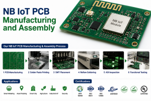
How Are IoT Controller and Switch PCBs Manufactured and Assembled?
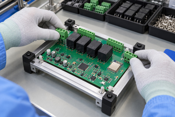
Turnkey IoT controller and switch PCB manufacturing follows a controlled process from component procurement to final assembly inspection. The assembly sequence must accommodate compact wireless electronics alongside relays, connectors, and power components.
Step 1: PCB Fabrication
Manufacture the bare PCB according to the approved stackup, copper specifications, drill files, and surface finish. Inspect critical dimensions and electrical separation features, then complete the specified bare-board electrical testing.
Step 2: Component Sourcing and Verification
Procure the approved MCUs, wireless modules, relays, MOSFETs, connectors, and passive components. Verify part numbers, packaging conditions, and component handling requirements. Substitutions require customer approval.
Step 3: SMT Assembly
Apply solder paste, place SMD components, and complete reflow soldering using a qualified process. Fine-pitch controller ICs, wireless modules, and power devices require careful placement and solder joint control.
Step 4: Through-Hole Assembly
Install relays, terminal blocks, and other THT components using an appropriate soldering method, such as selective soldering, wave soldering, or controlled manual soldering.
Through-hole solder fill, terminal alignment, and component temperature limits are particularly important for relay-based switching boards.
Step 5: Assembly Inspection
Use visual inspection and AOI to identify applicable placement and soldering defects. X-ray inspection may be used for components with hidden solder joints.
Inspect relay pins, terminal connections, and other areas not fully covered by AOI using suitable inspection methods.
Step 6: Programming, Testing, and Packaging
Perform the agreed firmware programming and functional tests using customer-provided instructions and acceptance criteria. Package finished PCB assemblies with appropriate ESD and mechanical protection, along with specified identification labels.
How Are IoT Controller and Switch PCB Assemblies Tested?
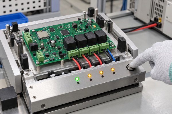
Functional testing verifies whether an assembled controller powers up, processes commands, and operates its switching outputs correctly. Inspection alone cannot confirm that a relay controller or smart switch will operate as intended.
| Test Item | What Is Checked | Possible Failure Indication |
|---|---|---|
| Power-Up Test | Supply voltage, regulated outputs, startup behavior, and current consumption | No startup, abnormal current, or unexpected reset |
| MCU and Firmware Test | Firmware version, control inputs, and output commands | Incorrect firmware, missing response, or wrong output mapping |
| Relay Switching Test | Relay activation, NO/NC contact operation, and channel switching | Relay fails to operate or switches the wrong channel |
| MOSFET Output Test | Switching waveform, output voltage, and specified current behavior | Missing output, incorrect switching, or abnormal voltage drop |
| Wireless Communication Test | Module initialization, connection, command reception, and response | Failed connection, missing response, or unstable communication |
| Load and Thermal Validation | Switching operation and temperature under specified operating loads | Unexpected reset, excessive heating, or unstable switching |
Production functional testing and product qualification testing should be defined separately. Routine production tests may cover power, firmware, communication, and switching outputs, while extended load cycling, thermal testing, and electrical safety verification may require dedicated qualification procedures.
For example, a relay controller may operate normally without a load but reset when switching an inductive device. Representative load testing can identify problems that basic continuity checks cannot reveal.
EBest Circuit supports customer-defined functional testing, with the testing scope, equipment, and acceptance criteria confirmed before production. Product-level safety and wireless certification remain separate from routine PCBA inspection.
How Can You Validate Prototypes Before Mass Production?
Prototype validation should establish an approved manufacturing configuration that can be reproduced in later production batches. Passing a functional test on one sample does not automatically confirm that the assembly process is ready for volume production.
Step 1: Review Prototype Manufacturing Results
Check the initial assemblies for solder defects, component discrepancies, manufacturing deviations, and mechanical fit issues. Resolve identified problems before production approval.
Step 2: Approve the Production Configuration
Confirm the PCB revision, BOM, approved component substitutions, assembly drawings, and firmware version. Different product variants should use clearly identified configurations.
Step 3: Establish Repeatable Production Controls
Approve assembly instructions, inspection requirements, programming procedures, and functional test criteria. Record the accepted process requirements for future orders.
Step 4: Verify the Initial Production Batch
Perform first-article inspection and verify that production units match the approved configuration. Record deviations and obtain the necessary approvals before releasing affected assemblies.
Controlled BOM revisions, firmware identification, and production records help prevent mixed configurations and inconsistent assembly quality. These controls are especially useful when one IoT controller platform supports several switching variants.
What Affects IoT Controller and Switch PCB Assembly Lead Time?
Component availability, PCB fabrication requirements, mixed SMT/THT assembly, and test preparation are the main factors affecting turnkey IoT controller and switch PCB assembly lead time.
| Lead Time Factor | Impact on Production |
|---|---|
| Relay and Wireless Module Availability | Long-lead components or unavailable approved part numbers can delay material preparation |
| PCB Fabrication Requirements | Special copper thickness, manufacturing tolerances, or additional processes may extend fabrication |
| Mixed SMT/THT Assembly | Relays, connectors, and other through-hole components require additional assembly operations |
| Firmware and Test Preparation | Incomplete programming instructions or unavailable test fixtures can delay production release |
| Engineering Changes | Revised PCB files, BOM changes, or substitutions may require additional review and approval |
Finalizing the BOM, PCB revision, assembly instructions, and testing requirements before order release helps reduce avoidable delays.
For repeat production, notify the manufacturer of component, firmware, or hardware changes before procurement begins. Even when the PCB layout remains unchanged, these changes may affect assembly preparation and testing.
Why Choose EBest Circuit for Turnkey IoT Controller and Switch PCB Assembly?
EBest Circuit provides integrated PCB manufacturing, component sourcing, SMT/THT assembly, and testing support for custom IoT controllers and smart switches. Our turnkey services help OEM customers coordinate manufacturing activities while maintaining approved component and quality requirements.
- One-Stop PCB and PCBA Manufacturing: Coordinate PCB fabrication, component sourcing, mixed SMT/THT assembly, inspection, and agreed testing through one manufacturing partner rather than multiple separate suppliers.
- 1+3 Technical Team: Every EBest PCBA project is supported by a 1+3 technical team (PE + DFM + Process + Quality) to review manufacturability, component requirements, assembly processes, and quality risks before production.
- Component Sourcing and BOM Control: Verify approved component specifications and manage substitutions with customer authorization, helping prevent incorrect relays, wireless modules, or other components from entering production.
- Inspection and Functional Testing Support: Combine assembly inspection with customer-defined electrical and functional testing to identify applicable soldering, component, and switching faults before delivery.
- Prototype-to-Production Support: Maintain approved PCB revisions, assembly instructions, component records, and inspection requirements as projects move from sample builds to repeat orders.
- Quality Management and Traceability: EBest Circuit holds ISO 9001, ISO 13485, IATF 16949, and AS9100D certifications and supports production traceability records for up to 15 years, subject to applicable project requirements.
For OEM customers, turnkey manufacturing reduces the number of suppliers that must be coordinated, while controlled component sourcing, assembly procedures, and inspection records help maintain consistency across production batches.
What Information Do You Need for a Turnkey IoT Controller and Switch PCBA Quote?
A complete RFQ package helps confirm the turnkey manufacturing scope, component availability, assembly requirements, and testing arrangements.
Please provide:
- PCB Manufacturing Files: Gerber or ODB++ data, drill files, stackup, board thickness, copper specifications, and fabrication drawings.
- Assembly Files: Approved BOM, manufacturer part numbers, CPL/pick-and-place files, and assembly drawings.
- Electrical Requirements: Input voltage, output ratings, load type, switching configuration, and applicable insulation requirements.
- Programming and Testing: Firmware files where required, programming instructions, test procedures, and acceptance criteria.
- Order Information: Prototype or production quantity, hardware revision, required delivery schedule, and shipping destination.
- Turnkey Scope: Confirm whether you need full turnkey manufacturing, partial component sourcing, or assembly using customer-supplied parts.
Send your production files to sales@bestpcbs.com for manufacturing review and a project-specific quotation.
FAQs About IoT Controller and Switch PCB Assembly
Q1: Who owns custom test fixtures after a turnkey PCBA order is completed?
A1: Ownership depends on the agreed purchase and tooling terms. Customer-funded fixtures can be returned, retained for repeat orders, or handled under another agreed arrangement. Confirm ownership and storage requirements before production.
Q2: Can relay PCB assemblies be cleaned after soldering?
A2: It depends on the relay construction and manufacturer instructions. Not all relays are suitable for PCB washing. Cleaning fluids or moisture entering an unsealed relay can affect contact performance.
Q3: Does conformal coating affect smart switch components?
A3: It can. Relay vents, connector contacts, mechanical switches, and other sensitive areas may require masking. Coating compatibility and exclusion areas should be confirmed before application.
Q4: How should ESD-sensitive wireless modules be handled?
A4: Wireless modules and controller ICs should be handled using appropriate ESD-protected packaging, workstations, and storage procedures. Moisture-sensitive devices must also follow their specified handling and reflow requirements.
Q5: Can lead-free soldering be used for smart switch PCB assemblies?
A5: Yes, provided the PCB materials and components are compatible with the selected process. The solder alloy, soldering method, and temperature profile must remain within the applicable component limits.
Q6: Can assembled controller PCBs include serial numbers or QR codes?
A6: Yes. Customer-defined serial numbers, QR codes, or labels can identify individual assemblies, hardware revisions, and production batches. The marking method and required traceability information should be agreed before production.
Q7: How should assembled relay controller PCBs be packaged for shipping?
A7: Finished boards should use suitable ESD-protective packaging and mechanical protection for protruding relays, terminals, and connector pins. Packaging should prevent electrostatic damage, component movement, and mechanical stress during transportation.
Q8: Is burn-in testing necessary for every IoT smart switch PCB?
A8: Not necessarily. Burn-in requirements depend on the product’s reliability targets and qualification plan. Routine functional testing does not automatically require extended burn-in, and additional screening should use agreed test conditions and acceptance criteria.
Conclusion
Reliable IoT controller and switch PCB assembly requires accurate component sourcing, controlled SMT/THT processes, and functional testing matched to the intended switching application. A coordinated turnkey manufacturing process helps reduce supplier handoffs while maintaining consistent assembly requirements from prototypes to volume production.
EBest Circuit provides turnkey IoT controller and switch PCB assembly solutions for OEM customers worldwide. From PCB fabrication and component procurement to assembly, inspection, and testing support, we help bring your approved controller design into production. Send your Gerber files, BOM, assembly requirements, and order quantity to sales@bestpcbs.com for DFM review and a customized manufacturing quotation.
You may also like

Tags: IoT Controller PCB Assembly, Relay Controller PCB Assembly, Smart Switch PCB Assembly, Turnkey PCB Assembly