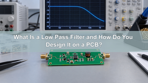
A low pass filter allows lower-frequency signal content to reach the output while attenuating content above a selected frequency range. On a PCB, its real response depends on more than the schematic formula: source and load impedance, component tolerance, parasitic coupling, return paths and the measurement setup can all move the cutoff frequency or reduce stopband attenuation.
What Is a Low Pass Filter?
A low pass filter is a frequency-selective circuit that passes the lower part of a signal spectrum and progressively reduces higher-frequency components. The range that should pass is the passband. The range that must be attenuated is the stopband, and the frequencies between them form the transition band.
A real filter does not switch from full output to zero output at one exact frequency. Its amplitude and phase change through the transition band. Filter order, response type, loading and component accuracy determine how quickly that change occurs and how closely the manufactured board matches the calculated response.
What Does a Low Pass Filter Do?
A low pass filter keeps wanted low-frequency information while reducing higher-frequency noise, harmonics or switching energy. In an RC low pass filter, capacitor reactance decreases as frequency rises. The resistor and capacitor therefore form a frequency-dependent divider: low-frequency voltage appears at the output, while more high-frequency current is diverted through the capacitor.
An LC low pass filter uses a series inductor and a shunt capacitor. Inductor reactance increases with frequency, so the inductor opposes high-frequency current while the capacitor provides a short return path for it. The same low-pass function can therefore be built for small analog signals, power rails or RF paths, but the component ratings and layout requirements are different.
How Does a Low Pass Filter Graph Show Cutoff Frequency?
A low pass filter graph normally plots gain in decibels against frequency on a logarithmic axis. The low-frequency region shows the passband gain. The curve then bends through the transition band and falls toward the stopband. For a first-order RC stage, the cutoff frequency is usually the point where the output magnitude is 0.707 of the passband value, or approximately -3 dB.
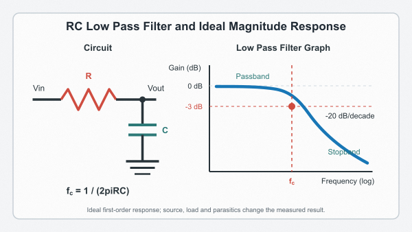
The -3 dB point does not mean that all higher frequencies disappear. A first-order filter approaches a -20 dB/decade slope; a two-pole filter approaches -40 dB/decade after the response enters its asymptotic region. Passband ripple, stopband attenuation and phase response must be read separately rather than inferred from the cutoff value alone.
What Is the Low Pass Filter Transfer Function?
For an ideal RC stage with the output taken across the capacitor, the transfer function is H(s) = 1 / (1 + sRC). It describes both magnitude and phase as frequency changes. This expression assumes an ideal source and a high-impedance load; a real source resistor or load network changes the denominator and therefore changes the pole.
How Do You Calculate an RC Low Pass Filter?
For an unloaded first-order RC low pass filter, the cutoff-frequency formula is:
fc = 1 / (2πRC)
For example, R = 10 kΩ and C = 15.9 nF produce a calculated cutoff close to 1 kHz. If the capacitor is changed to 10 nF, the calculated cutoff rises to about 1.59 kHz. These values are starting points, not guaranteed measurements.
A low pass filter calculator or RC low pass filter calculator can solve the same equation quickly. Before accepting its result, add source resistance to the intended series resistance and check whether the next-stage input resistance loads the network. Then round to available component values and calculate the new result instead of assuming the original number remains exact.
The low pass filter circuit diagram must also identify the output node. Taking the output across the capacitor creates a low-pass response; taking it across the resistor in the same series network creates a high-pass response.
Low Pass Filter vs High Pass Filter: What Is the Difference?
The difference is which side of the cutoff region remains in the passband. A low pass filter keeps lower frequencies, while a high pass filter keeps higher frequencies. The physical parts may be similar, so the output node and component arrangement must be checked rather than judging from the component list alone.
| Filter response | Frequency range passed | Typical task |
|---|---|---|
| Low pass filter | Below the cutoff region | Noise reduction, smoothing, anti-aliasing and bass routing |
| High pass filter | Above the cutoff region | DC blocking, drift removal and low-frequency interference rejection |
| Band-pass filter | Between a lower and upper cutoff | Channel selection and narrow-band signal conditioning |
How can you tell if a filter is high-pass or low-pass? Follow the signal from input to output and check where the frequency-dependent impedance sits. Then verify the expected response with the transfer function or a frequency sweep. A label such as “RC filter” is not enough because the same resistor and capacitor can implement either response.
What Types of Low Pass Filter Circuits Can You Use?
The circuit type should match the signal level, current, frequency range, insertion loss and required attenuation. An RC network is often suitable for low-power analog filtering. RL and LC networks become useful when current, loss or RF behavior makes a resistor undesirable. An active low pass filter adds an amplifier for buffering, gain or a controlled multi-pole response.
| Low pass filter circuit | Main advantage | Important limitation |
|---|---|---|
| RC low pass filter | Simple, inexpensive and easy to calculate | Insertion loss and source/load interaction |
| RL low pass filter | Uses rising inductive reactance to block high frequency | Inductor size, resistance and self-resonance |
| LC low pass filter | Lower resistive loss and steeper response | Resonance, damping, current rating and PCB parasitics |
| Active low pass filter | Buffering, gain and precise second-order stages | Amplifier bandwidth, noise, supply and stability |
| Digital low pass filter | Programmable response after conversion | Requires sampling, processing and an analog front end |
What Is a Discrete Low Pass Filter?
A discrete low pass filter is built from separate resistors, capacitors, inductors or active devices rather than a dedicated filter IC. It gives the designer direct control over values and layout, but performance depends on the selected parts and their placement. “Discrete” does not automatically mean passive; a circuit using a separate op amp and passive components is also a discrete implementation.
How Do First-Order and Second-Order Low Pass Filters Differ?
A first-order low pass filter has one pole and approaches -20 dB/decade attenuation. It uses fewer components and is usually less sensitive to value ratios, but its transition may be too gradual when unwanted content is close to the passband.
A second-order low pass filter has two poles and approaches -40 dB/decade. The additional pole provides more attenuation, but damping and Q now affect peaking, phase and transient behavior. Cascading stages creates higher orders; each added stage increases component sensitivity and makes loading, noise and stability more important.
| Design question | First-order filter | Second-order filter |
|---|---|---|
| Asymptotic roll-off | -20 dB/decade | -40 dB/decade |
| Component count | Lower | Higher |
| Response control | Cutoff mainly set by one time constant | Cutoff and Q depend on component ratios or topology |
| Best fit | Gentle noise reduction or isolation | Sharper transition with controlled damping |
When Should You Use a Butterworth Low Pass Filter?
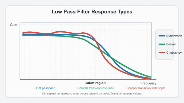
A Butterworth low pass filter is appropriate when a flat passband magnitude is more important than the fastest step settling or the sharpest possible transition. It avoids passband ripple and provides a balanced general-purpose response for signal conditioning, audio and data-acquisition circuits.
How Do Bessel and Chebyshev Responses Compare?
A Bessel response gives priority to phase linearity and time-domain waveform shape, so it can reduce overshoot and ringing. A Chebyshev response accepts passband ripple to obtain a steeper transition for the same order. The correct response depends on allowable amplitude error, settling behavior and stopband attenuation; the filter family should not be selected from roll-off alone.
How Does a Sallen-Key Low Pass Filter Work?
A Sallen-Key low pass filter uses an amplifier with two resistors and two capacitors to form a second-order active stage. The amplifier buffers the filter from the following load, while component ratios and closed-loop gain determine cutoff frequency and Q. Different value sets can implement Butterworth, Bessel or other responses.
The amplifier must have adequate gain-bandwidth product, slew rate, input common-mode range, output swing and drive capability at the intended signal level. An ideal calculator may return valid resistor and capacitor ratios while ignoring an amplifier that cannot support the required response.
A multiple-feedback filter is another active second-order option. It can be useful at higher frequencies or for particular Q values, but it inverts the signal and loads the input differently. Compare topology requirements before assigning component values and PCB space.
What Should You Set a Lowpass Filter To?
Set the passband high enough to preserve the highest wanted frequency and require enough attenuation where unwanted content begins. There is no universal cutoff setting because an audio crossover, sensor input, ADC anti-aliasing network and power-rail filter solve different problems.
| Application | Starting design input | What must be checked |
|---|---|---|
| Subwoofer or audio crossover | Intended crossover band and adjacent driver response | Combined amplitude, phase and acoustic response |
| Sensor signal | Highest useful sensor bandwidth | Settling time and attenuation of known interference |
| ADC anti-aliasing | Signal bandwidth and sample rate | Stopband attenuation before frequencies can alias |
| Power rail | Switching frequency and load-transient spectrum | Voltage drop, damping, current and transient response |
For an audio low pass filter for subwoofer use, the electrical setting must be reviewed with the loudspeaker and enclosure response. For an ADC, selecting a cutoff below half the sample rate is not enough by itself; the required attenuation at the first aliasing band determines filter order and transition width.
Where Are Low Pass Filters Used?
Low pass filters are used wherever a circuit must preserve slower signal changes and reject higher-frequency content. Common examples include sensor conditioning, audio crossovers, ADC inputs, DAC reconstruction, control loops, power supplies and RF harmonic suppression.
- Sensor and instrumentation boards: reduce broadband noise before amplification or conversion without removing the measured event.
- Data-acquisition inputs: limit bandwidth before sampling and control the interaction with the converter input network.
- Audio circuits: separate bass content or remove ultrasonic noise while maintaining the intended gain and phase relationship.
- Power electronics: reduce ripple and conducted switching energy while carrying DC and transient current.
- RF circuits: suppress harmonics or out-of-band energy while controlling insertion loss, impedance and component self-resonance.
The application determines which performance number matters most. A sensor filter may prioritize low noise and settling, a power filter must survive current and transients, and an RF filter may be dominated by pad, via and transmission-line parasitics.
How Do You Design a Low Pass Filter Board?
Begin with measurable electrical requirements rather than a preferred topology. Define passband gain, cutoff or passband edge, required attenuation and the frequency where that attenuation must be reached. Then add source impedance, load impedance, signal amplitude, DC bias, power rails, temperature range and available PCB area.
How Do Source and Load Impedance Change the Response?
Source resistance adds to an intended series resistor, while the receiving circuit can load the shunt branch. Both effects move the cutoff and may change passband gain. At higher frequencies, traces, connectors and cables can behave as transmission lines. Our impedance-controlled PCBs support designs where stack-up and copper geometry are part of the electrical model. We target impedance tolerance of +/-10% above 50 ohms and +/-5 ohms at or below 50 ohms, subject to engineering review.
Which Component Properties Affect Accuracy?
Resistor and capacitor tolerance move an RC pole. Temperature coefficient and long-term drift can move it further. Capacitor value may change with DC bias, temperature and frequency; ESR and ESL add loss and resonance. Inductors require checks for DC resistance, saturation current, Q and self-resonant frequency. Use tighter tolerances where the response is sensitive to them rather than applying expensive parts everywhere.
Simulate the circuit with realistic tolerances and impedances, then select available component values. The schematic, BOM, stack-up and test limits should describe the same filter; otherwise fabrication can be correct while the measured board still misses the electrical target.
How Should a Low Pass Filter Be Laid Out on a PCB?
A low pass filter board should keep the critical signal loop and its return path compact. Place each shunt capacitor close to the node it filters, keep high-impedance nodes short and separate the filter from clocks, switching nodes and other fast edges. Long traces can add enough inductance or capacitance to bypass the intended response.
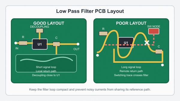
- Place amplifier decoupling capacitors beside the supply pins with a short return connection.
- Keep the input and output of an LC stage physically separated so stray coupling does not bypass the filter.
- Do not force noisy load current through the same narrow return path used by the filter reference.
- Avoid long test-point stubs on sensitive high-frequency nodes.
- Preserve the intended impedance through connectors and controlled traces when the filter operates at RF.
Audio, control and sensor filters are commonly implemented on FR4 PCBs. Higher-frequency networks may require low-loss materials and controlled launches. We also manufacture RF PCBs with specified high-frequency laminates when the operating frequency and loss budget justify them.
How Do You Test a Low Pass Filter Circuit?
Test the assembled board over a frequency range that includes the passband, transition band and required stopband. A network analyzer can measure magnitude and phase directly; a swept generator and oscilloscope can also be used when their source and input impedances are included in the setup.
- Verify component values, orientation and assembly against the released BOM.
- Apply the specified source amplitude, DC bias and source impedance.
- Measure passband gain, cutoff frequency, ripple and stopband attenuation.
- Repeat with the intended load and relevant supply or temperature conditions.
- Use step or pulse testing to check overshoot, ringing and settling when time-domain behavior matters.
Probe capacitance, fixture loss and long ground leads can alter the result. Record instrument settings and fixture details so prototype and production measurements can be compared under the same conditions. A correct bare-board continuity test does not prove the assembled filter meets its frequency response.
Low Pass Filter FAQs
Is a Passive Low Pass Filter the Same as an RC Filter?
No. An RC low pass filter is one type of passive low pass filter. Passive designs can also use RL or LC networks. The correct choice depends on frequency, current, allowable loss, component size and the source and load impedances.
Does a Low Pass Filter Block Every Frequency Above Cutoff?
No. A practical low pass filter attenuates frequencies progressively through its transition band. The cutoff frequency marks a defined response point, commonly -3 dB for a first-order RC stage, rather than a boundary above which the output instantly becomes zero.
Can a Low Pass Filter Calculator Predict PCB Parasitics?
A basic calculator normally solves ideal component equations. It does not automatically include trace inductance, pad capacitance, component ESR and ESL, source impedance, load impedance or electromagnetic coupling. These effects must be added to simulation and verified on the assembled board when they are significant.
When Is an LC Filter Preferable to an RC Filter?
An LC filter is often preferable when resistive voltage drop and power loss must be minimized, such as in power rails or higher-current paths. It can also provide a steeper response, but resonance, damping, saturation current, self-resonant frequency and PCB layout must be controlled.
What Files Are Needed for a Low Pass Filter PCB Quote?
For a low pass filter PCB quotation, we review the Gerber or ODB++ data, stack-up, material and impedance specifications, BOM, assembly drawings, quantity and required test conditions. At EBest Circuit (Best Technology), we manufacture bare PCBs and provide PCB assembly services for low pass filter circuits. Our assembly options include SMT, through-hole and mixed builds, 01005 components and BGA pitch down to 0.25 mm, subject to review of the actual board, package and process requirements.
For quotation and engineering review, provide Gerber or ODB++ data, drill files, stack-up and impedance requirements, the BOM with manufacturer part numbers, pick-and-place data and an assembly drawing. Add the required cutoff or passband edge, source and load impedance, signal level, supply rails, stopband attenuation and test conditions. These inputs allow us to review the PCB construction, component placement and assembly scope against the intended response.
A calculated low pass filter becomes a repeatable PCB assembly only when its surrounding impedance, layout, component tolerances and acceptance test are defined. Send the current design package to sales@bestpcbs.com for fabrication and assembly review.
You may also like





Tags: Filter Circuit, Low Pass Filter, pcb design, RC Low Pass Filter