





The main difference in an inductive load vs resistive load comparison is what happens to electrical energy. A resistive load uses the energy as it arrives, mainly as heat or light. An inductive load stores part of it in a magnetic field, so current builds more slowly, lags voltage in AC operation, and must keep flowing briefly when the circuit is switched off.
For a designer or buyer, that distinction changes real decisions: how much current the source must deliver, which relay or MOSFET rating applies, whether a turn-off clamp is needed, and how the high-current loop should be routed on the PCB. The sections below move from identifying the load to checking its waveforms, choosing a switch, controlling the transient, and specifying the parts needed for a reliable build.
What Is a Resistive Load?
A resistive load is one in which resistance dominates, so current follows the applied voltage with little phase shift. This makes its steady-state current comparatively easy to calculate, but temperature and startup conditions can still change the result.
For an ideal resistor, current follows Ohm’s law:
I = V / R
If voltage rises while resistance remains constant, current rises in the same proportion. With a sinusoidal AC supply, voltage and current cross zero and reach their peaks at nearly the same time. The phase angle is therefore close to 0°, and the displacement power factor is close to 1.
Heating elements, power resistors, and resistive load banks are common examples. An incandescent lamp is mostly resistive after it warms up, but its cold filament resistance is much lower than its operating resistance. It can therefore draw substantial inrush even though it is not an inductive load.
Treat “resistive” as the dominant operating behavior, not a promise that current never changes. Once that distinction is clear, the different behavior of a coil is easier to see.
What Is an Inductive Load?
An inductive load uses a winding or coil to create a magnetic field, and that stored magnetic energy resists rapid changes in current. The current therefore rises over time at turn-on and needs a discharge path at turn-off.
Motors, transformers, relay coils, solenoids, contactor coils, and electromagnetic actuators all contain significant inductance. With sinusoidal AC, current in an ideal inductor lags voltage by 90°. A real coil also has winding resistance, core loss, leakage inductance, and parasitic capacitance, so its actual phase angle is smaller and changes with frequency and operating point.
This behavior matters most during startup, PWM control, faults, and switch-off. A motor may draw high current before back EMF develops, while an energized relay or solenoid can generate a high voltage when its current path is interrupted.
If magnetic energy affects current rise, phase, or turn-off stress, the circuit must be designed as an inductive-load circuit. The next comparison shows how that changes the electrical requirements.
What Is the Difference Between Inductive and Resistive Loads?
In an inductive load vs resistive load comparison, a resistive load mainly dissipates energy, while an inductive load temporarily stores energy and can return it to the circuit. That one difference explains most of the changes in phase, power factor, switch rating, and transient protection.
The most useful comparison is not the label on the appliance, but the behavior seen at the interface you are designing:
| Characteristic | Resistive load | Inductive load |
|---|---|---|
| Dominant property | Resistance | Inductance and winding resistance |
| AC phase | Current nearly in phase with voltage | Current lags voltage |
| Energy behavior | Mainly dissipates energy | Stores energy in a magnetic field |
| Power factor | Near 1 for an ideal linear load | Usually lagging and below 1 |
| Switch-off response | No large magnetic-energy kick | Can generate a voltage transient |
| Typical examples | Heaters, power resistors, load banks | Motors, transformers, relays, solenoids |
How Do Voltage and Current Behave in Resistive and Inductive Loads?
Voltage and current move together in a mainly resistive load, while an inductive load needs voltage to change its current. The difference appears as phase lag in steady-state AC and as a finite current rise or decay during switching.
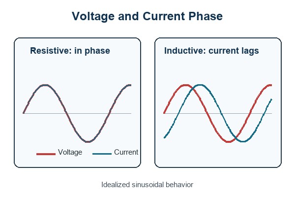
For a linear inductor driven by a sinusoidal steady-state signal, the magnitude of inductive reactance is:
XL = 2πfL
Here, f is frequency in hertz, L is inductance in henries, and XL is measured in ohms. Higher frequency or higher inductance produces more opposition to AC current. A real coil also includes winding resistance, so its impedance and phase angle depend on both R and XL.
The formula is not a complete model for every condition. At DC steady state, an ideal inductor’s reactance is zero and the coil current is limited mainly by winding resistance. During turn-on or turn-off, the time-domain relationship V = L × di/dt is the relevant starting point. Saturation, core loss, and nonlinear drive electronics can further change the measured behavior.
Use XL = 2πfL for sinusoidal steady-state analysis, then check the time-domain waveform for switching stress. Those two views prevent a resistance-only measurement from hiding the important part of the load.
How Does Power Factor Differ Between Inductive and Resistive Loads?
An ideal resistive load has a power factor of 1, while a linear inductive load has a lagging power factor below 1. A lower power factor means the source and conductors may carry more RMS current for the same useful power.
Power factor is the ratio of real power to apparent power:
PF = P / S
For a single-phase sinusoidal load:
P = VRMS × IRMS × PF
At the same voltage and real power, reducing PF raises the RMS current. That increases conductor and connector loss, voltage drop, transformer loading, and thermal stress.
A low true-PF reading does not automatically prove that the load is inductive. Rectifier-capacitor inputs and other nonlinear electronics can have poor power factor because their current is distorted rather than simply phase-shifted. Compare true PF, displacement PF, current waveform, and circuit topology before choosing a correction method.
Power factor tells you how heavily the source is being used, but the waveform tells you why. That distinction matters when you move from a theoretical load to real equipment.
What Are Common Resistive and Inductive Load Examples?
Examples are useful only when they reveal the behavior the source or switch must handle. Many appliances contain several load types, so the internal circuit and operating mode matter more than a broad product category.
Typical resistive loads
- Heating elements: Convert electrical energy into heat; their cold and hot resistance may differ.
- Power resistors: Provide controlled dissipation for braking, biasing, balancing, or test loads.
- Resistive load banks: Apply predictable real power to generators, UPS systems, and power supplies.
- Incandescent filaments: Behave mainly as resistance when hot but can draw high cold-filament inrush.
Typical inductive loads
- Motors: Use windings and magnetic fields; startup current depends on motor type, mechanical load, supply, and drive method.
- Transformers: Draw magnetizing current and reflect the secondary load to the primary.
- Relay and contactor coils: Store magnetic energy while energized and release it when switched off.
- Solenoids and actuators: Convert magnetic force into motion and often require a controlled release time.
Refrigerators, air conditioners, pumps, and fans usually include motors, but the complete product may also contain heaters, capacitors, inverters, and switch-mode power supplies. Their input may be a mixed or nonlinear load even though one internal component is clearly inductive.
Use the example to find the likely behavior, then confirm it from the datasheet or measurement. The following checks turn that initial classification into usable design limits.
How Can You Check for Inductive Loads vs Resistive Loads?
The reliable way to identify a load is to combine circuit information, manufacturer data, and measurements at the real operating condition. No single clue is sufficient for sizing a switch or suppression network.
- Inspect the circuit. Identify heaters, resistor networks, motors, transformers, relays, solenoids, and power-conversion stages. This establishes what behavior is plausible.
- Read the device data. Look for PF, L/R time constant, coil resistance, inductance, locked-rotor current, inrush, switching category, or a separate inductive-load rating. Match the stated voltage and operating mode.
- Measure voltage, current, and power. A power analyzer can show real power, apparent power, true PF, displacement PF, and waveform distortion. Lagging current supports an inductive classification; narrow current pulses point to nonlinear electronics.
- Capture startup. A current probe can reveal motor or transformer inrush, but inrush by itself is not proof of inductance because cold lamps and capacitor-input supplies can also surge.
- Capture turn-off. A correctly rated oscilloscope probe can show overshoot, ringing, and current-decay time. These measurements directly inform switch-voltage margin and clamp selection.
- Repeat under worst conditions. Supply tolerance, temperature, mechanical load, PWM duty, cable length, and magnetic saturation can change the result.
For mains or other high-energy circuits, use appropriately rated instruments and qualified personnel. The goal is not merely to name the load; it is to establish the current, voltage, timing, and energy that the source and switch must survive.
A useful classification ends with measured limits, not just “inductive” or “resistive.” Those limits are what you need to select a switching device without relying on a misleading headline rating.
How Do Inductive and Resistive Loads Affect Switching Devices?
A switch rated for 10 A resistive service is not automatically safe at 10 A with a motor, relay coil, or solenoid. Inductive loads can add inrush, slower current interruption, contact arcing, semiconductor avalanche energy, and repetitive voltage stress.
For relays and contactors, use the manufacturer’s rating for the actual load category, voltage, current, power factor, or L/R time constant. The permissible current is often lower for an inductive-load condition because stored electromagnetic energy makes interruption more demanding. A large number printed on the relay may describe only a resistive test condition.
For MOSFETs, IGBTs, and smart switches, check nominal and startup current, repetitive pulse current, drain or collector voltage, safe operating area, clamp or avalanche energy, switching loss, junction temperature, and fault response. Verify the gate-drive conditions at the lowest drive voltage and worst temperature rather than assuming the typical curve represents the finished product.
Select the switch from the load-specific datasheet condition and the measured waveform—not from equal steady-state amperes. If the current cannot stop cleanly when the switch opens, the next design task is controlling where its stored energy goes.
Why Can Inductive Loads Produce Voltage Spikes When Switched Off?
The spike appears because an energized inductor’s current needs a path after the switch opens. If the circuit does not provide one, the voltage rises until current can flow through an unintended path.
The basic relationship is:
V = L × di/dt
A faster attempted change in current produces a larger induced voltage. The rising voltage may appear across a MOSFET, relay contact gap, wiring capacitance, connector, or insulation. It can lead to avalanche stress, contact arcing, EMI, logic resets, insulation damage, or gradual degradation that is not obvious during an initial bench test.
A mainly resistive load does not store comparable magnetic energy, so it normally lacks this large inductive kick. Parasitic inductance is still present in every current loop, however, and fast edge rates can create overshoot even with a nominally resistive load.
The practical question is not whether the spike exists, but where the current will flow and how high the voltage will rise. A deliberately chosen clamp answers both questions.
How Can You Protect a Circuit When Switching an Inductive Load?
A protection network must keep the switch voltage safe while letting the load release at the required speed. The best choice depends on AC or DC operation, stored energy, repetition rate, and the acceptable current-decay time.
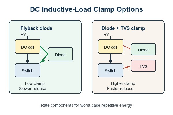
- Flyback diode: Connect a diode reverse-biased across a DC relay or solenoid coil during normal operation. It provides a low-voltage current path at turn-off, but the slow decay can delay mechanical release.
- Diode with Zener or TVS: A higher clamp voltage lets current fall faster. Check the switch voltage margin and the diode’s repetitive pulse energy at the maximum load current and temperature.
- RC snubber: Use a resistor-capacitor network to reduce dv/dt, ringing, and contact arcing in a suitable AC or DC circuit. Choose values from the load and verify them on the measured waveform.
- MOV: Use a metal-oxide varistor where its clamp voltage, surge energy, repetition rate, aging, and safety approvals match the application.
- Integrated clamp or recirculation path: Confirm the driver’s allowable inductive energy, thermal duty, and demagnetization time. An internal clamp is not an unlimited energy sink.
A higher clamp voltage shortens current-discharge time, while a lower clamp voltage keeps the voltage down but extends the decay. This is why a simple flyback diode can be ideal for one coil yet too slow for a fast solenoid. A DC flyback diode must not be copied blindly across an AC coil, where it would conduct during one half-cycle.
Choose the clamp from voltage margin, energy, repetition, and release-time requirements together. Once the circuit is selected, PCB placement and routing determine whether that protection works at the switch.
What Should You Consider When Designing a PCB for Inductive Loads?
Design the PCB around peak current and the turn-off current loop, not just the coil’s steady-state current. Trace impedance, connector placement, and clamp location directly affect overshoot, EMI, and ground disturbance.
- Current capacity: Size copper, vias, connectors, and terminals for startup, stall, PWM, and fault current where applicable.
- Clamp location: Place the flyback diode, TVS, or snubber close to the load connector or switching path it protects. Long traces add inductance between the clamp and the switch.
- Loop area: Keep the switch, load connection, clamp, and return path compact to reduce radiated and coupled noise.
- Return path control: Keep load and clamp current out of sensitive analog, reference, and communication returns.
- Switch margin: Check measured overshoot, pulse energy, SOA, gate drive, thermal impedance, and repetitive duty at worst supply and temperature.
- Spacing and insulation: Set creepage, clearance, slots, coating, and connector spacing from the working voltage, expected transients, pollution degree, and applicable safety requirements.
- Thermal path: Include conduction loss, switching loss, clamp dissipation, copper heating, and enclosure airflow.
- Test access: Provide safe points for gate drive, switch node, current sense, and supply so startup and turn-off can be checked with the actual cable and load.
Before release, test minimum and maximum supply, relevant temperature extremes, the worst mechanical load, repeated switching duty, and the intended cable length. A stable running-current reading does not prove that the turn-off transient or thermal cycle is safe.
A robust PCB gives the stored energy a short, intentional path and leaves enough electrical and thermal margin for repetition. Those same requirements should appear in the BOM and sourcing package, not remain implicit in the schematic.
FAQs About Inductive and Resistive Loads
Q1: Is an electric heater always a purely resistive load?
A1: Usually it is predominantly resistive, but “purely” is too strong. A coiled heating element and its wiring have some parasitic inductance, and thermostats or electronic controllers can change the input waveform. For switch selection, use the heater’s cold resistance, rated current, and controller topology rather than assuming the hot-state wattage tells the whole story.
Q2: Why does a relay coil have both a resistance value and an inductance value?
A2: The wire contributes resistance, while the winding and magnetic core contribute inductance. Resistance largely sets the final DC coil current; inductance determines how quickly that current rises and falls. Both values are needed to understand drive current and release behavior.
Q3: Can a multimeter resistance reading tell whether a load is inductive?
A3: No. A resistance reading shows the DC resistance seen by the meter, but it does not reveal phase angle, saturation, inrush, or turn-off energy. Use the schematic or datasheet first, then measure current and switch-node voltage under the intended operating condition.
Q4: Should a flyback diode be added to a resistive heater controlled by a DC switch?
A4: Not simply because the load is switched. A flyback diode is intended to carry stored inductive current. A heater may still need protection for wiring inductance, controller transients, or a mixed load, but the correct device could instead be a TVS, snubber, or another network chosen from the measured transient.
Q5: Is a refrigerator an inductive load when sizing an inverter or generator?
A5: Its compressor motor makes startup capability important, but the appliance is a mixed load. Fans, heaters, controls, and an inverter drive may all contribute. Use the manufacturer’s input and surge data, or measure startup with the actual operating mode, rather than applying a generic motor multiplier.
Q6: Does power factor correction make an inductive load behave like a resistor?
A6: It can make the combined load look closer to unity power factor at the supply, but it does not remove the motor or transformer’s inductance. The winding still stores magnetic energy, so its startup, control, and switch-off requirements remain. Correction equipment must be sized for the actual operating range and harmonics rather than added as a generic capacitor.
Choosing the right relay, MOSFET, driver, diode, TVS, connector, and passive components is easier when the load behavior is defined before parts are ordered. Send EBest Circuit your BOM with exact manufacturer part numbers or approved alternatives, required quantities, target delivery date, and traceability or quality requirements for a component-sourcing quotation. If PCBA is included, add the schematic, Gerber or ODB++ files, load voltage and current, startup or stall current, switching frequency, clamp method, and test requirements. Email sales@bestpcbs.com to start the review.
You may also like






Tags: Circuit Protection, Inductive Load, pcb design, Resistive Load