





The 0603 resistor power rating is commonly around 0.1 W, or 100 mW, for many general-purpose thick-film resistors. That figure is a useful reference, but it is not a universal limit for every 0603 component. The usable wattage depends on the resistor series, construction, resistance value, maximum working voltage, temperature, pulse conditions, and PCB thermal environment.
A reliable design therefore requires more than checking whether a simple power calculation falls below 0.1 W. The 0603 resistor power rating must be considered together with temperature derating, working-voltage limits, pulse capability, and design margin. This article explains how to make those checks and when a standard 0603 should be replaced with a higher-power part, a larger package, or a resistor network.
What Is the Typical Power Rating of a 0603 Resistor?
For many general-purpose thick-film products, the typical 0603 resistor power rating is approximately 0.1 W, equal to 100 mW or 1/10 watt. However, 0603 identifies the package size rather than a fixed electrical rating.
An imperial 0603 resistor has nominal dimensions of about 0.06 × 0.03 inch, corresponding to roughly 1.6 × 0.8 mm. Different resistor technologies can occupy the same footprint while carrying different wattage ratings.
| 0603 Resistor Type | Typical Power Rating |
|---|---|
| General-purpose thick film | Around 0.1 W |
| Precision thin film | 0.063–0.1 W |
| Lower-power series | 0.063–0.075 W |
| Enhanced-power 0603 | 0.125 W or higher |
| High-power 0603 | 0.15–0.2 W or higher |
| Current-sense 0603 | Series-dependent |
| Pulse-resistant 0603 | Series-dependent |
The exact 0603 resistor power rating must come from the selected component datasheet because package size alone does not define wattage.
Why Do Different 0603 Resistors Have Different Power Ratings?
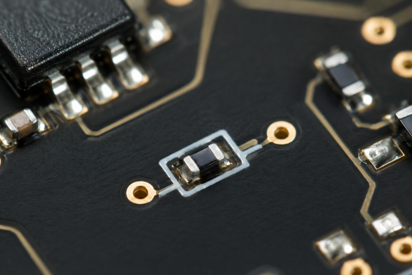
Two 0603 resistors can have the same external dimensions and very different continuous power capabilities. The difference comes mainly from how the resistive element generates, spreads, and transfers heat.
The main factors are:
- Resistive material: Thick-film, thin-film, metal-element, and other technologies have different thermal behavior and allowable element temperatures.
- Element geometry: The shape and thickness of the resistive path influence current density and local hot spots.
- Ceramic substrate: The substrate helps move heat from the resistive element toward the terminations.
- Termination construction: End terminations provide a major thermal path from the component into the solder pads and PCB copper.
- Maximum element temperature: Different product families are designed to tolerate different internal temperatures.
- Qualification conditions: Published power can depend on specified pad dimensions, PCB construction, copper area, ambient temperature, or terminal temperature.
This matters when one resistor is substituted for another. Two parts listed as 10 kΩ, 1%, 0603 may fit the same footprint but still differ in wattage, voltage capability, temperature behavior, and pulse performance.
For a power-sensitive position, compare the 0603 resistor power rating, maximum working voltage, derating characteristics, pulse capability, operating-temperature range, and TCR before approving a substitute.
How Do You Read a 0603 Resistor Power Rating from a Datasheet?
A datasheet should be treated as an operating envelope, not as a single wattage number. Seeing “0.1 W” in a specification table is only the first step.
| Datasheet Parameter | Technical Significance |
|---|---|
| Rated Power | Continuous allowable dissipation |
| Reference Temperature | Temperature at which full rated power applies |
| Derating Curve | Reduction in allowable power at elevated temperature |
| Maximum Working Voltage | Highest permitted continuous voltage |
| Overload Voltage | Short-duration electrical stress limit |
| Operating Temperature | Permitted operating temperature range |
| Pulse Specification | Allowable pulse power or energy |
| TCR | Resistance variation with temperature |
First, confirm that the value belongs to the 0603 package or metric 1608 equivalent. Datasheets often place 0402, 0603, 0805, and 1206 values next to one another, so using the wrong row can lead to an incorrect design limit.
Next, identify the thermal condition associated with the published 0603 resistor power rating. A resistor may support full rated power only up to a specified ambient or terminal temperature. Above that point, the available wattage falls according to the derating curve.
Then check the maximum working voltage separately. A high-resistance 0603 resistor can dissipate relatively little power while still exceeding its allowable continuous voltage.
Before approving the part, verify:
- Rated power at the actual operating temperature
- Maximum continuous working voltage
- Short-duration overload limits
- Pulse or surge capability
- Operating-temperature range
- Any mounting conditions stated in the datasheet
The component is suitable only when all applicable limits are satisfied at the same time.
How Do You Calculate Power Dissipation for a 0603 Resistor?
The electrical load should be calculated before comparing the circuit with the 0603 resistor power rating.
The standard relationships are:
P = V × I
P = I² × R
P = V² ÷ R
where:
- P = power in watts
- V = voltage across the resistor
- I = current through the resistor
- R = resistance in ohms
Consider a 1 kΩ resistor with 5 V across it:
P = 5² ÷ 1000 = 0.025 W
The resistor dissipates 25 mW. For a resistor nominally rated at 0.1 W, that is 25% of the nominal rating before temperature derating is applied.
Now place 10 V across the same 1 kΩ resistor:
P = 10² ÷ 1000 = 0.1 W
The dissipation rises to 100 mW, equal to the nominal rating of many standard 0603 resistors.
The key relationship is that, with a fixed resistance, power rises with the square of voltage. Doubling the voltage from 5 V to 10 V increases resistor dissipation by four times.
A practical calculation should include:
- Maximum supply voltage: Use the highest credible operating voltage, not just the nominal rail value.
- Resistance tolerance: Select the tolerance extreme that produces the highest stress in the actual circuit.
- Maximum continuous current: Typical current may underestimate thermal load.
- Startup and shutdown conditions: Some circuits expose resistors to higher stress before steady-state operation begins.
- Fault conditions: Include abnormal states when the resistor is expected to survive them.
- Duty cycle: Switched loads require both peak and average power to be considered.
After calculating the worst-case value, compare it with the temperature-derated 0603 resistor power rating, not only the room-temperature value.
How Do Resistance Value and Maximum Working Voltage Limit 0603 Resistor Power?
Power and voltage limits are related, but they are not interchangeable. A resistor can remain below its thermal limit while already exceeding its permitted working voltage.
For a given resistance and power, the theoretical voltage is:
V = √(P × R)
Using a nominal 0.1 W power limit:
| Resistance | Voltage at 0.1 W |
|---|---|
| 100 Ω | 3.16 V |
| 1 kΩ | 10 V |
| 10 kΩ | 31.6 V |
| 100 kΩ | 100 V |
| 1 MΩ | 316 V |
These are mathematical power values, not guaranteed safe working voltages.
For example, a 1 MΩ resistor mathematically reaches 0.1 W at approximately 316 V. If the selected 0603 series has a maximum working voltage far below 316 V, the voltage specification becomes the limiting factor long before the 0603 resistor power rating is reached.
In practice:
- Low-resistance values: Current and thermal dissipation are more likely to become limiting factors.
- High-resistance values: Maximum working voltage may become the dominant constraint.
This distinction matters in high-voltage dividers, DC bus sensing, capacitor discharge networks, battery monitoring, high-impedance measurement paths, and power-supply feedback circuits.
If one resistor cannot meet the required voltage and wattage simultaneously, a series network can distribute both voltage and dissipation. PCB creepage and clearance still have to meet the total circuit-voltage requirements.
How Does Temperature Derating Affect the 0603 Resistor Power Rating?
The nominal 0603 resistor power rating normally applies only within a defined temperature range. Above the manufacturer’s reference temperature, the allowable continuous power decreases.
This reduction is called power derating.
Suppose, purely as an example, that a 0.1 W resistor permits full power up to 70°C and then derates linearly to zero at 155°C.
At 100°C:
Remaining power ratio = (155 − 100) ÷ (155 − 70) = 64.7%
The allowable continuous dissipation would be:
0.1 W × 64.7% = 64.7 mW
The temperatures in this example are illustrative rather than universal. The correct values must come from the selected resistor series.
The practical lesson is simple: a nominal 100 mW resistor may no longer support 100 mW once the PCB becomes hot.
Local temperature can rise because of:
- MOSFETs and regulators: Heat spreads through nearby PCB copper.
- Power inductors and transformers: Magnetic components often create concentrated hot areas.
- High-power LEDs: Their thermal load can raise the surrounding board temperature.
- Closely spaced loaded resistors: Several moderate heat sources can combine into one local hot spot.
- Sealed enclosures: Restricted convection increases internal PCB temperature.
- Elevated ambient conditions: Outdoor, automotive, industrial, and enclosed electronics may operate far above room temperature.
When the 0603 resistor power rating is being used close to its limit, base derating on the temperature seen by the resistor during real operation, not simply on room temperature.
How Do PCB Layout and Thermal Conditions Affect 0603 Resistor Power Handling?
A surface-mount resistor transfers much of its heat through the end terminations and solder joints into the PCB. That makes the board part of the resistor’s thermal environment.
Several layout choices can influence operating temperature:
- Pad geometry: A suitable land pattern provides a predictable electrical, mechanical, and thermal connection.
- Connected copper area: Wider copper regions can spread heat more effectively than narrow traces.
- Copper thickness: Additional copper can improve local heat spreading where the circuit permits it.
- Thermal vias: In suitable layouts, vias can transfer heat toward internal planes or the opposite side of the board.
- Component spacing: Separating loaded resistors from MOSFETs, regulators, inductors, and LEDs reduces thermal coupling.
- Airflow: Natural or forced airflow changes how quickly heat leaves the PCB surface.
- Internal copper planes: Large connected copper areas can alter the local thermal path and board temperature.
One issue that is easy to miss is thermal accumulation. A single resistor dissipating moderate power may remain within limits. Put ten similarly loaded resistors into the same small area, however, and the surrounding PCB can become considerably warmer.
Thermal testing deserves particular attention when:
- Several resistors dissipate meaningful continuous power
- The PCB operates inside a sealed enclosure
- Power semiconductors are located nearby
- The calculated load approaches the derated limit
- Prototype temperatures differ from thermal estimates
PCB layout can help control temperature, but it should not be used to redefine the manufacturer’s 0603 resistor power rating.
How Much Power Margin Should You Use for a 0603 Resistor?
There is no universal rule requiring every 0603 resistor to operate at exactly 50%, 60%, or another fixed percentage of its rating.
A useful margin depends on the worst-case load, actual temperature, component tolerances, transient conditions, and required service life.
For example, a 0.1 W resistor dissipating 40 mW uses 40% of its nominal rating. A resistor dissipating 80 mW uses 80%. That comparison is meaningful only before temperature derating is applied.
If the actual PCB temperature reduces the allowable wattage to 65 mW, then an 80 mW load is already outside the permitted range even though it is below the nominal 100 mW value.
When deciding how much margin is enough, consider:
- Worst-case continuous dissipation: Base the calculation on the highest credible normal voltage or current.
- Derated allowable power: Compare the actual load with the rating available at the real operating temperature.
- Supply tolerance: A modest increase in voltage can create a much larger increase in resistor power.
- Resistance tolerance: Component variation can affect current and dissipation depending on the circuit.
- Startup and transient behavior: Short periods of additional loading should not be ignored.
- Local temperature: Heat from neighboring components can reduce the remaining margin.
- Expected operating life: Continuous high temperature leaves less room for aging and long-term drift.
Some designs use 50% of nominal power as an internal derating target, but that is a project rule rather than a universal standard.
A better rule is to keep worst-case continuous dissipation comfortably below the temperature-derated 0603 resistor power rating under actual operating conditions.
How Much Pulse or Surge Power Can a 0603 Resistor Handle?
A short pulse can sometimes exceed the continuous 0603 resistor power rating because the event ends before the entire resistor reaches thermal equilibrium.
That does not mean pulse capability can be estimated by multiplying the continuous wattage by an arbitrary factor.
Four variables are especially important:
- Pulse duration: A 10 µs event and a 100 ms event at the same peak power create very different thermal stresses.
- Peak voltage and current: Instantaneous electrical stress must remain within the applicable pulse limits.
- Pulse energy: Energy deposited during the event influences localized heating and element damage.
- Repetition rate: Frequent pulses may not leave enough cooling time between events.
For repetitive pulses, average power also matters:
Average power = energy per pulse × pulse repetition frequency
A resistor may therefore survive a single startup event but fail when the same pulse occurs hundreds or thousands of times per second.
Pulse capability deserves close attention in gate-drive circuits, snubber networks, capacitor charging and discharge paths, inrush circuits, switching converters, surge-sensing networks, and motor-control electronics.
A standard 0.1 W resistor and a pulse-resistant 0.1 W resistor can behave very differently under short overloads. For pulsed operation, check the pulse-load curve, overload specification, or energy limit for the exact resistor series rather than relying on the continuous 0603 resistor power rating.
How Do Standard and High-Power 0603 Resistors Differ?
A high-power 0603 resistor is intended to provide more continuous dissipation within approximately the same 1.6 × 0.8 mm footprint.
That makes it attractive when PCB space is tight, but higher wattage does not automatically make it the better part for every application.
| Parameter | Standard 0603 | High-Power 0603 |
|---|---|---|
| Continuous Power | Usually lower | Higher |
| Package Size | 0603 | 0603 |
| Thermal Capability | Conventional | Enhanced |
| Working Voltage | Series-dependent | Series-dependent |
| Pulse Capability | Series-dependent | Series-dependent |
| Tolerance / TCR | Product-dependent | Product-dependent |
| Cost | Usually lower | Often higher |
A high-power version is most useful when:
- Board area cannot increase, but more continuous power margin is required.
- Normal operating dissipation is too close to the derated limit of a standard part.
- The PCB runs warm, and a resistor series with a more suitable thermal specification is available.
- The higher-power part still meets the required resistance, tolerance, TCR, voltage, and availability requirements.
It is less helpful when another parameter is causing the problem:
- Excess working voltage: Higher wattage does not automatically mean a higher voltage rating.
- Severe pulses: A dedicated pulse-resistant resistor may be the better choice.
- Precision requirements: Higher rated power does not guarantee lower TCR, lower noise, or better long-term stability.
- Environmental requirements: Automotive, anti-sulfur, humidity, and other qualifications remain independent specifications.
The 0603 resistor power rating is only one part of the selection decision. Identify the real limiting parameter before paying for a higher-power component.
How Does 0603 Power Rating Compare with 0402, 0805 and 1206 Resistors?
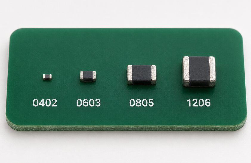
Larger resistor packages usually support more conventional continuous power because they provide a larger body and thermal path into the PCB.
| Package | Approx. Metric Size | Common General-Purpose Power |
|---|---|---|
| 0402 | 1.0 × 0.5 mm | Around 0.063 W |
| 0603 | 1.6 × 0.8 mm | Around 0.1 W |
| 0805 | 2.0 × 1.25 mm | Around 0.125 W |
| 1206 | 3.2 × 1.6 mm | Around 0.25 W |
These values are representative rather than guaranteed ratings. Specialized resistor families can differ substantially.
The package choice affects more than wattage:
- 0402: Useful where board density is critical and resistor dissipation is very low.
- 0603: Offers a practical balance of compact size, availability, assembly handling, and moderate power.
- 0805: Provides more thermal headroom with only a moderate increase in board area.
- 1206: Offers significantly more physical area where higher dissipation is required and space is available.
The 0603 vs 0805 power rating decision becomes particularly relevant when a standard 0603 is already close to its usable thermal limit. In that situation, moving to an 0805 may be simpler and more robust than operating a specialized 0603 near its maximum 0603 resistor power rating.
Working voltage and pulse ratings should still be checked separately because package size alone does not define every electrical limit.
When Should You Replace a 0603 Resistor with a Larger Package or Multiple Resistors?
A 0603 resistor deserves reconsideration when its electrical and thermal margins become narrow under worst-case conditions.
Moving to 0805 or 1206 is often the simplest option when:
- Continuous dissipation approaches the derated 0603 limit.
- The PCB remains hot during normal operation.
- Long service life favors a lower component temperature.
- Available 0603 products do not provide enough working-voltage capability.
- Pulse conditions exceed the capability of suitable 0603 resistor families.
- Several limits are being approached at the same time.
A resistor network is another option.
Series resistors are useful when voltage is the primary constraint. They divide the total resistance, voltage, and power across several components.
Parallel resistors can distribute current and thermal dissipation when one component would otherwise carry too much load.
That approach introduces its own design considerations:
- Resistance tolerance: Electrical stress may not divide exactly as expected.
- TCR variation: Sharing can change as individual resistors heat.
- Unequal PCB temperature: Two nominally identical parts can operate differently when one sits closer to a heat source.
- Copper geometry: Layout affects both current distribution and temperature.
- Additional solder joints: More parts mean more placements and interconnections.
The best solution may be a high-power 0603, an 0805 or 1206 resistor, a series network, or a parallel network. The choice should follow the actual limiting parameter and the required 0603 resistor power rating margin rather than package preference alone.
What Causes a 0603 Resistor to Overheat, Drift or Fail on a PCB?
An overloaded resistor does not always burn or go open-circuit immediately. Prolonged electrical or thermal stress may first appear as resistance drift, unstable readings, discoloration, localized heating, or intermittent operation.
Common causes include:
- Excess continuous power: Higher-than-expected voltage or current can push dissipation above the allowable 0603 resistor power rating. Measure the real voltage across the component and calculate its actual load.
- Insufficient temperature derating: A resistor that works at room temperature may become overstressed once the PCB heats up. Check the local operating temperature, not only ambient room temperature.
- Excess working voltage: High-value resistors can exceed their voltage limit while still dissipating relatively little power.
- Pulse or surge overload: Switching circuits may expose the resistor to short but severe electrical stress. Examine pulse width, peak voltage, peak current, energy, and repetition rate.
- Thermal accumulation: Several loaded resistors or nearby power components can raise the temperature of the same PCB area.
- Incorrect resistor value: A BOM error or incorrect substitute can change circuit current enough to raise dissipation dramatically.
- Poor solder joints or excessive rework: Damaged terminations or weak joints can affect both electrical reliability and heat transfer.
- PCB flexure: Mechanical bending can crack the ceramic body, damage terminations, or weaken solder joints.
- Unsuitable environmental rating: Moisture, corrosive gases, sulfur compounds, contamination, and thermal cycling can gradually affect a resistor that was not selected for those conditions.
When a 0603 resistor repeatedly runs hot or fails, replacing it with the same part is not a root-cause fix. Measure the real electrical load and local temperature first, then compare those values with the resistor’s voltage, pulse, and derated power limits.
FAQs About 0603 Resistor Power Rating
Q1: Is a 0603 resistor the same as a 1608 resistor?
A1: Yes. Imperial 0603 corresponds approximately to metric 1608, which represents a body size near 1.6 × 0.8 mm. The two naming systems use different numbering conventions, so package codes should not be interpreted in the same way. Confirm the actual dimensions when selecting a footprint or substitute.
Q2: Are 0603 resistors polarized?
A2: No. A conventional 0603 chip resistor is non-polarized, so either electrical orientation provides the same basic resistance function. Production may still standardize orientation for inspection consistency or documentation, but reversing the component does not reverse its electrical behavior.
Q3: Can a 0603 resistor be used in an AC circuit?
A3: Yes, provided the resistor remains within its RMS power, peak-voltage, and frequency-related limits. For a sinusoidal waveform, heating is normally evaluated using RMS voltage or current. Higher-frequency circuits may require additional consideration of parasitic impedance.
Q4: Does frequency affect the resistance of a 0603 resistor?
A4: At low frequencies, a chip resistor behaves close to its nominal resistance. At higher frequencies, parasitic inductance and capacitance affect impedance. RF, microwave, and high-speed applications may therefore require resistor families with specified high-frequency performance.
Q5: Can a 0603 resistor be used as a fuse?
A5: A standard 0603 resistor should not be assumed to provide controlled fuse behavior. Its failure mode, opening time, and overload response are not defined like those of a purpose-designed fuse or fusible resistor. If predictable circuit protection is required, use a component specifically rated for that function.
Q6: What resistance values are available in the 0603 package?
A6: The available range depends on resistor technology and product family. General-purpose 0603 products cover a very broad resistance range, while precision, current-sense, high-value, or specialized parts may cover narrower ranges. The exact range should be confirmed for the selected series.
Q7: Do 0603 resistors have printed resistance codes?
A7: Many modern 0603 resistors have no readable top marking because the package is very small. Some product families may use abbreviated markings, but these are not enough to identify every electrical specification. The manufacturer part number and BOM remain the reliable references.
Q8: Can a multimeter measure a 0603 resistor while it is still on the PCB?
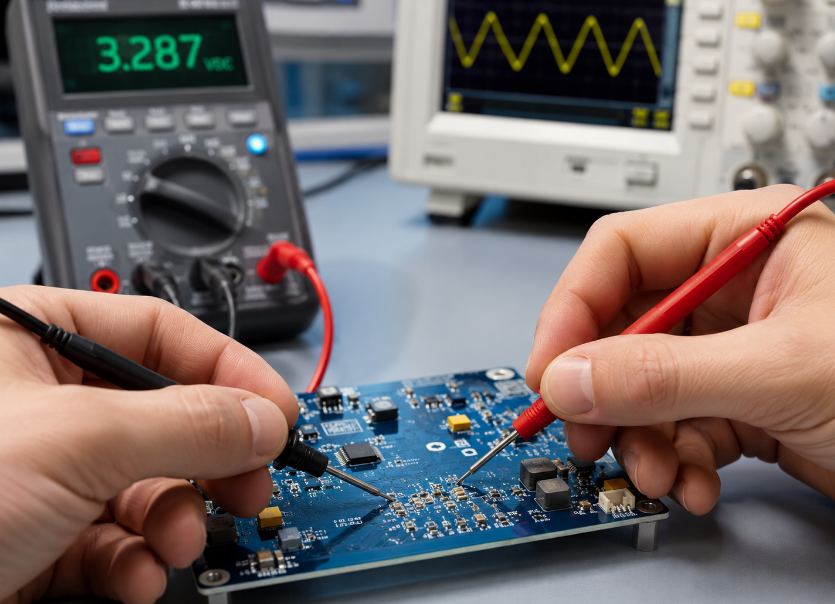
A8: It can, but an in-circuit reading may be influenced by parallel resistive paths, semiconductor junctions, capacitors, or other connected components. If the measured value does not match expectations, lifting one terminal or removing the resistor may be required for an accurate standalone measurement.
Q9: Can 0603 resistors be mounted on either side of a PCB?
A9: Yes. They can be assembled on the top or bottom side provided the PCB assembly process supports the selected placement and reflow sequence. Placement should still consider clearance, inspection access, nearby components, and the board’s mechanical environment.
Q10: Are 0603 resistors suitable for automated SMT assembly?
A10: Yes. The 0603 package is widely used in automated pick-and-place and reflow assembly. Proper land patterns, solder paste deposition, placement accuracy, and reflow control help maintain consistent solder joints and reduce defects such as tombstoning.
Q11: Can a 0603 resistor be used as a pull-up or pull-down resistor?
A11: Yes. Pull-up and pull-down functions generally dissipate relatively little power, making the 0603 package suitable for many digital circuits. The resistance value should be selected according to logic level, leakage current, switching speed, and required bias current rather than wattage alone.
Q12: What resistor tolerances are commonly available in 0603 packages?
A12: Common 0603 resistor families are available in tolerances such as 5%, 1%, 0.5%, 0.1%, and tighter values depending on the technology. Tighter tolerance does not automatically mean a higher 0603 resistor power rating; precision and power capability are separate specifications.
Q13: Is a 0603 resistor electrically different from a 0603 capacitor?
A13: Yes. The shared “0603” designation refers only to the approximate package dimensions. A resistor provides resistance, while a capacitor stores electrical charge and has capacitance, voltage, dielectric, and frequency characteristics. Identical package codes do not indicate equivalent electrical functions.
The 0603 resistor power rating is commonly around 0.1 W, but reliable component selection requires more than matching a resistor to that single number. The finished design must keep the component within its continuous power, working-voltage, temperature-derating, and pulse limits under the actual PCB operating conditions.
Calculate worst-case dissipation first, then check the result against the resistor’s usable power at the expected temperature. When the available 0603 resistor power rating margin becomes narrow, a high-power 0603, larger 0805 or 1206 package, or properly designed resistor network can provide a more robust solution than running a standard part close to its limit.
If your project involves power-sensitive resistor networks, high-voltage sensing, compact PCB layouts, prototype development, or PCB assembly, we can support PCB fabrication and PCBA production from prototype through volume manufacturing.
Send your Gerber files, BOM, assembly requirements, and order quantity to EBest Circuit sales@bestpcbs.com to request a technical review and PCB/PCBA quotation.
You may also like




Tags: 0603 Resistor, 0603 resistor derating, 0603 resistor power dissipation, 0603 Resistor Power Rating