MFD capacitor markings are not always consistent. One capacitor may be labeled 10 MFD, another 10 µF, while a bill of materials may specify 10 uF. Do these markings represent three different capacitance values?
In most capacitor-related contexts, 10 MFD, 10 µF, and 10 uF all refer to 10 microfarads. MFD is an older, non-SI abbreviation, µF is the modern unit symbol for microfarad, and uF is its keyboard-friendly alternative. Knowing the difference helps engineers correctly interpret legacy schematics, select replacement capacitors, prepare accurate BOMs, and avoid errors during full turnkey PCB assembly.
This MFD capacitor guide explains what MFD means on a capacitor, the differences between MFD, µF, and uF, how to convert capacitance units, how to choose a suitable replacement, and what engineers should verify before a capacitor enters PCBA production.
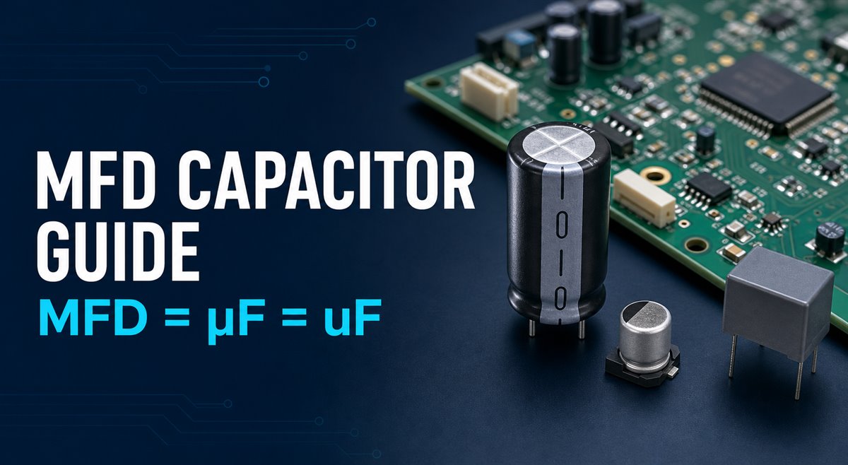
What Is an MFD Capacitor?
An MFD capacitor is usually a capacitor whose value is marked in microfarads using the older abbreviation MFD.
It may be:
- an aluminum electrolytic capacitor
- a film capacitor
- a motor start capacitor
- a motor run capacitor
- a power supply filtering capacitor
- a through-hole capacitor on a PCB
- an SMD capacitor listed in a BOM as a uF value
So, “MFD capacitor” describes the capacitance marking, not one single construction type.
For example, a 10 MFD capacitor and a 10 uF capacitor may have the same capacitance value, but they may still be completely different parts if their voltage, dielectric, polarity, ESR, package, or application is different.
What Does MFD Mean on a Capacitor?
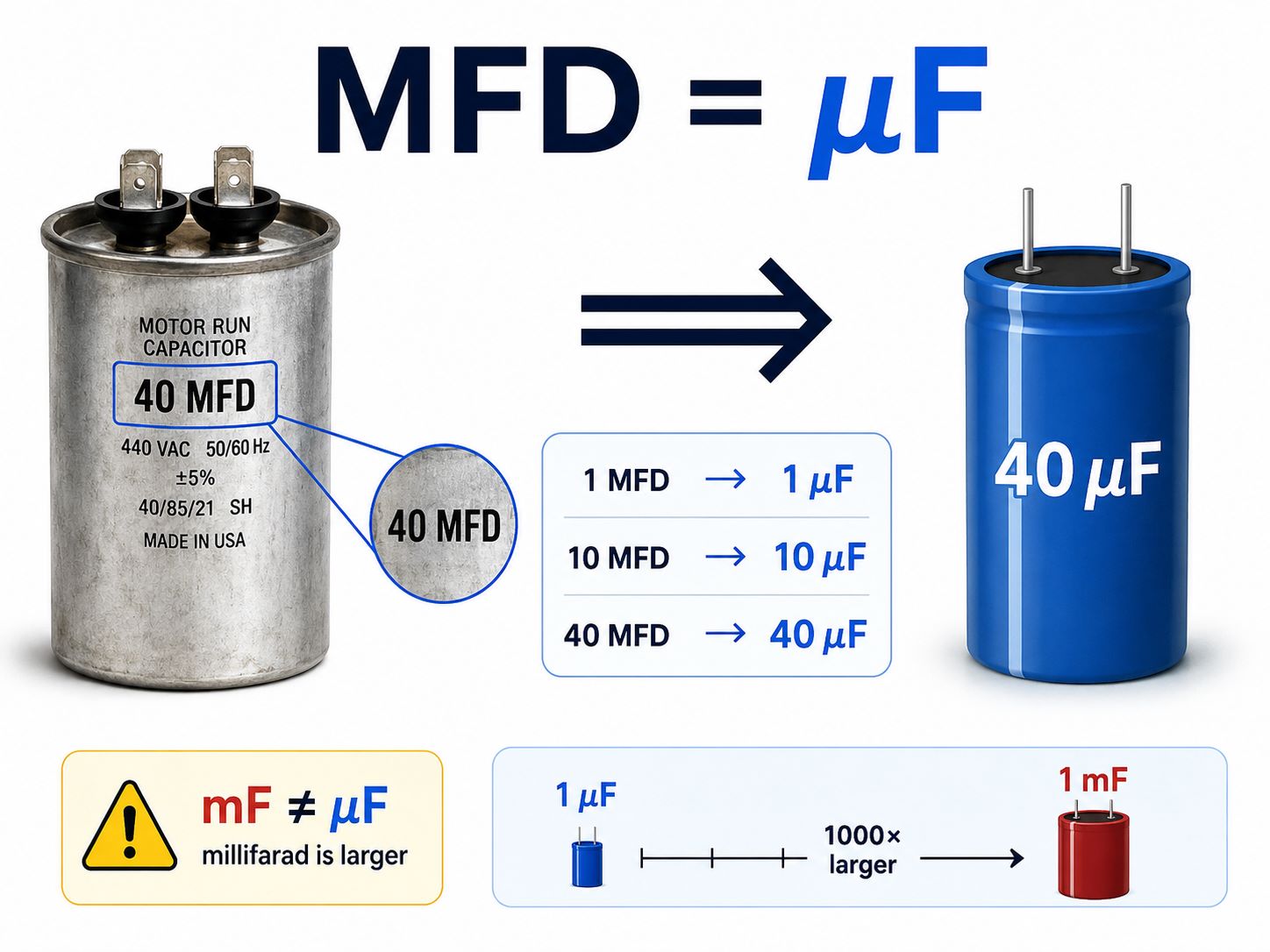
On many older capacitors, motor capacitors, appliance parts, and legacy schematics, MFD means microfarad. A microfarad is one-millionth of a farad:
1 microfarad = 1 µF = 1 uF = 0.000001 F = 10⁻⁶ F
For example:
- 1 MFD normally means 1 µF
- 10 MFD normally means 10 µF
- 40 MFD normally means 40 µF
- 100 MFD normally means 100 µF
The farad, symbolized by F, is the SI unit of capacitance. The prefix micro, symbolized by the Greek letter µ, means 10⁻⁶. Therefore, the preferred modern notation is µF.
The abbreviation MFD remains common because older documents and component markings often used “MF,” “MFD,” or “mfd” when the µ character was difficult to print or type.
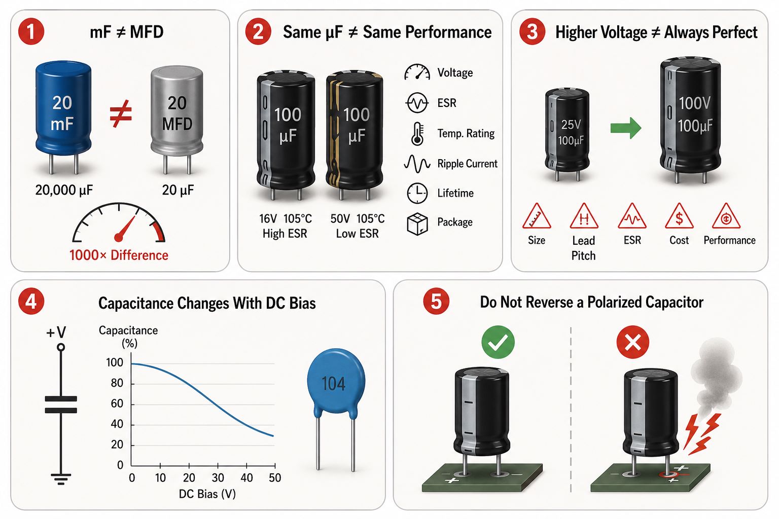
Important: In legacy capacitor markings, MFD usually means microfarad. In modern SI notation, however, mF means millifarad, which is 1,000 times larger than a microfarad. Always check the component, schematic, and manufacturer datasheet before making a replacement.
MFD vs µF vs uF: Are They the Same?
For the capacitor values normally seen in maintenance manuals and electronic component listings:
| Marking | Typical meaning | Status |
|---|---|---|
| MFD or mfd | Microfarad in legacy capacitor notation | Older, non-SI notation |
| µF | Microfarad | Correct modern SI-style symbol |
| uF | Microfarad | Plain-text substitute for µF |
| mF | Millifarad | Different unit; 1 mF = 1,000 µF |
Thus:
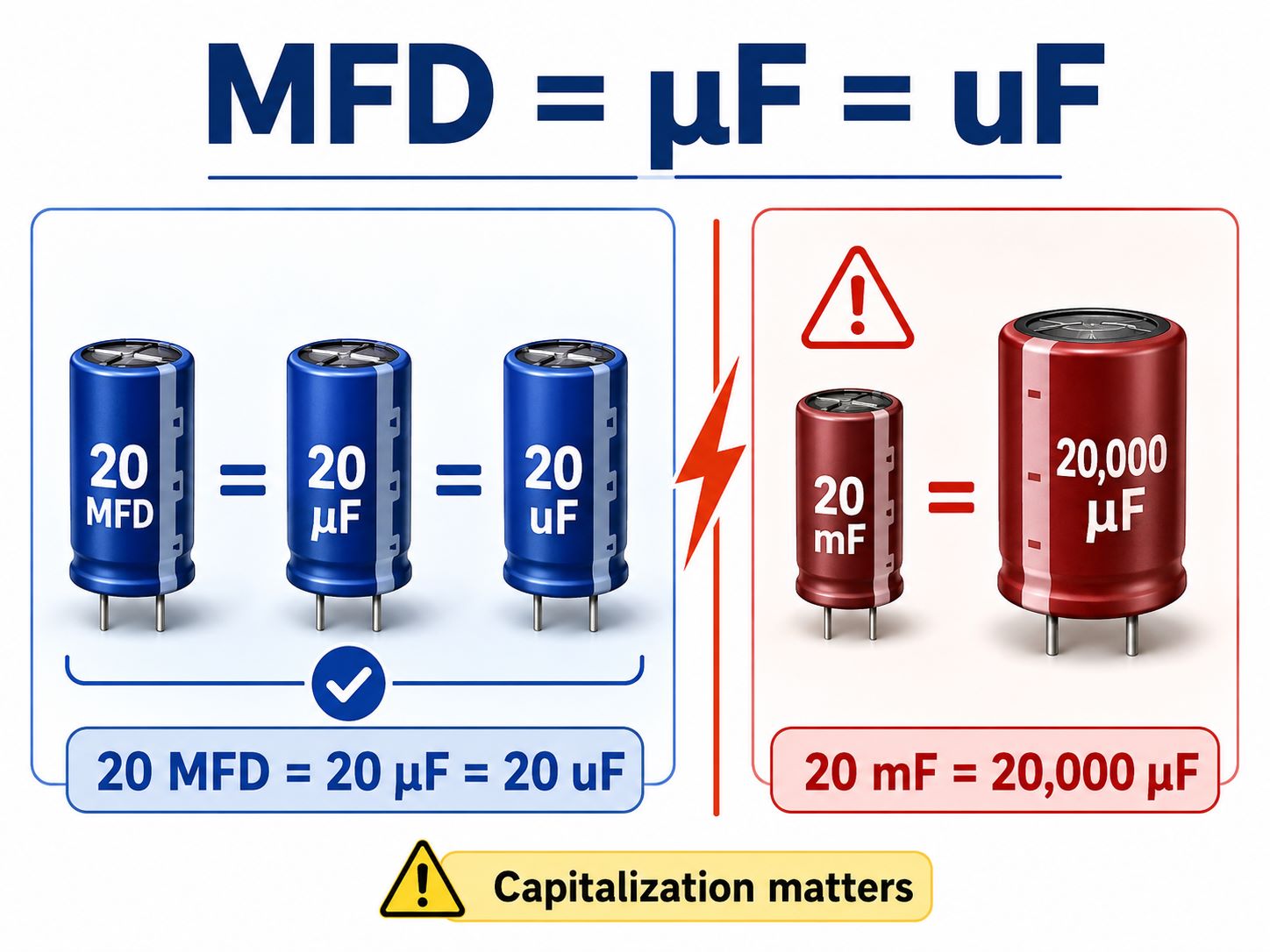
20 MFD = 20 µF = 20 uF
But:
20 mF = 20,000 µF
Capitalization matters. Confusing MFD with mF can result in selecting a capacitor with a drastically different value. In a professional BOM, drawing, or component database, using µF or uF is clearer than using MFD.
What Is a Microfarad?
A microfarad is a unit used to express capacitance. Capacitance describes how much electric charge a capacitor can store for a given voltage.
In simplified form:
C = Q / V
where:
- C is capacitance in farads
- Q is electric charge in coulombs
- V is voltage in volts
Capacitors with microfarad values are widely used for:
- power-supply filtering
- bulk energy storage
- voltage smoothing
- signal coupling
- timing circuits
- motor starting and running
- audio crossover networks
- local power decoupling
The required value depends on the circuit. A 0.1 µF ceramic capacitor may suppress high-frequency noise near an IC, while a 100 µF electrolytic capacitor may handle lower-frequency ripple on a power rail. Capacitance alone does not define whether two capacitors are interchangeable.
Microfarad Conversion Chart
Capacitance may be shown in farads, millifarads, microfarads, nanofarads, or picofarads.
| Unit | Symbol | Equivalent value |
|---|---|---|
| Farad | F | 1 F |
| Millifarad | mF | 10⁻³ F |
| Microfarad | µF or uF | 10⁻⁶ F |
| Nanofarad | nF | 10⁻⁹ F |
| Picofarad | pF | 10⁻¹² F |
Useful conversions include:
- 1 F = 1,000,000 µF
- 1 mF = 1,000 µF
- 1 µF = 1,000 nF
- 1 µF = 1,000,000 pF
- 1 nF = 1,000 pF
Common capacitor value conversions
| Microfarads | Nanofarads | Picofarads |
|---|---|---|
| 0.001 µF | 1 nF | 1,000 pF |
| 0.01 µF | 10 nF | 10,000 pF |
| 0.1 µF | 100 nF | 100,000 pF |
| 1 µF | 1,000 nF | 1,000,000 pF |
| 10 µF | 10,000 nF | 10,000,000 pF |
For example, a component marked 104 usually represents 100,000 pF, which equals 100 nF or 0.1 µF. The first two digits are significant figures, and the third digit indicates the number of zeros in picofarads.
How to Read an MFD Capacitor
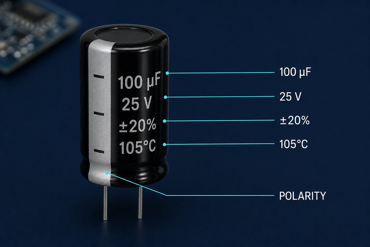
A capacitor label may include more than its capacitance. Depending on the capacitor type, look for:
- Capacitance: such as 10 MFD, 10 µF, or 10 uF
- Rated voltage: such as 16 VDC, 50 VDC, or 450 VAC
- Tolerance: such as ±5%, ±10%, or ±20%
- Polarity: a stripe, plus sign, or minus sign on polarized capacitors
- Temperature rating: such as 85°C or 105°C
- Series or manufacturer code
- Safety or approval markings
Consider a capacitor marked:
100 µF 25 V ±20% 105°C
This indicates a nominal capacitance of 100 microfarads, a maximum rated DC voltage of 25 volts under specified conditions, a capacitance tolerance of ±20%, and a maximum category temperature of 105°C.
The voltage rating is not the capacitor’s operating voltage or a value that the capacitor forces into the circuit. It is a limit that must not be exceeded.
Common MFD Capacitor Values and Applications
Some MFD values appear frequently in electronics, power supplies, motors, appliances, and PCB assemblies.
| Value | Common Use |
|---|---|
| 0.1 uF / 0.1 MFD | Noise filtering, local decoupling |
| 1 uF / 1 MFD | Signal coupling, timing, filtering |
| 10 uF / 10 MFD | Power rail filtering, small bulk storage |
| 47 uF / 47 MFD | Power smoothing, DC circuits |
| 100 uF / 100 MFD | Bulk capacitance, ripple reduction |
| 470 uF / 470 MFD | Power input filtering |
| 35 MFD or 45 MFD | Often seen in motor capacitor applications |
| 45/5 MFD | Dual-value motor run capacitor marking |
In PCB and PCBA projects, EBest Circuit does not decide the circuit value for the customer. The capacitance value should come from the customer’s schematic, BOM, approved AVL, or engineering specification. Our role is to help check whether the selected part matches the manufacturing and assembly files.
Can You Replace an MFD Capacitor With a uF Capacitor?
Yes—if MFD is being used to mean microfarad, a capacitor marked in uF can replace it. However, matching the capacitance notation is only the beginning.
Before replacing a capacitor, verify the following parameters.
1. Capacitance
- Use the capacitance specified by the circuit designer or equipment manufacturer. A replacement should normally have the same nominal µF value unless the manufacturer explicitly allows a range.
- Changing capacitance may affect ripple, timing, resonance, motor torque, cutoff frequency, or control-loop stability. Do not assume that “close enough” is safe in every application.
2. Voltage rating
- The replacement capacitor’s voltage rating must be equal to or higher than the original requirement. Never substitute a lower voltage rating.
- A higher voltage rating may be electrically acceptable, but it can increase component size, cost, and lead spacing. Confirm that it fits the PCB and suits the application.
3. Capacitor type and dielectric
An aluminum electrolytic, polymer, film, tantalum, and multilayer ceramic capacitor can have the same nominal capacitance while behaving differently.
Check characteristics such as:
- equivalent series resistance (ESR)
- ripple-current rating
- leakage current
- dielectric behavior
- frequency response
- temperature range
- expected service life
- failure mode
For example, replacing an electrolytic capacitor with an MLCC purely because both are labeled 10 µF may not provide the same effective capacitance under DC bias.
4. Polarity
- Many aluminum electrolytic and tantalum capacitors are polarized. Reversing polarity can cause excessive leakage, heating, venting, or failure.
- Non-polarized film and ceramic capacitors do not have the same orientation requirement. Never infer polarity from capacitance value alone.
5. Package and dimensions
Confirm:
- SMD or through-hole construction
- case size
- height limit
- lead pitch
- terminal style
- PCB footprint
- polarity-mark orientation
- clearance from nearby parts
A part may be electrically suitable but mechanically incompatible with the board.
6. Operating environment
- Review temperature, vibration, humidity, expected lifetime, surge conditions, and applicable safety requirements. Motor-run, motor-start, EMI suppression, and general-purpose PCB capacitors are not automatically interchangeable.
How to Test an MFD Capacitor With a Multimeter?
Many digital multimeters include a capacitance test function. If the meter supports capacitance measurement, it can help check whether a capacitor is close to its rated MFD value.
A basic test process may include:
- Turn off power and discharge the capacitor safely.
- Remove the capacitor from the circuit if the surrounding circuit affects measurement.
- Set the multimeter to capacitance mode.
- Connect the probes to the capacitor terminals.
- Read the measured value.
- Compare the result with the rated MFD/uF value and tolerance.
For example, a 100 uF ±20% capacitor may be acceptable within a broad range, depending on its specification and application.
Testing limitations:
- In-circuit measurement may be inaccurate.
- ESR problems may not appear in a simple capacitance test.
- Leakage current may require other test equipment.
- A capacitor can measure close to the rated value but still fail under voltage, heat, or ripple current.
- Motor capacitors and high-voltage capacitors require proper safety handling.
For PCBA projects, capacitor testing may be part of incoming inspection, functional testing, troubleshooting, or failure analysis, depending on customer requirements.
MFD Capacitor Polarity, Voltage, and Installation Checks
Capacitance does not determine polarity. Some capacitors are polarized; others are not.
Common polarized capacitors:
- aluminum electrolytic capacitors
- tantalum capacitors
- some polymer capacitors
Common non-polarized capacitors:
- ceramic capacitors
- many film capacitors
- some motor capacitors
Polarity errors can cause leakage, overheating, venting, poor function, or board failure. During PCBA assembly, capacitor polarity should be checked across several files:
- schematic
- BOM
- PCB footprint
- silkscreen
- centroid file
- assembly drawing
- component datasheet
- actual component marking
One common risk is that different capacitor types mark polarity differently. Many aluminum electrolytic capacitors mark the negative side, while some tantalum capacitors mark the positive side. The exact datasheet should be used as the final reference.
Voltage rating also needs attention. A replacement capacitor should not have a lower voltage rating than required. A higher voltage rating may be acceptable, but the part may become larger, more expensive, or incompatible with the PCB footprint.
MFD Capacitors in PCB and PCBA Manufacturing
The term “MFD capacitor” is most often a marking convention, not a special capacitor construction. In a PCBA project, engineers should translate legacy notation into a precise, orderable component specification.
Instead of entering only 10 MFD in the BOM, define the actual requirements, for example:
- 10 µF, ±20%, 25 V, aluminum electrolytic, SMD, 105°C, specified ESR and ripple current, defined case size
- This reduces ambiguity during component sourcing, engineering review, and assembly.
BOM normalization
Use one capacitance format consistently. For a modern BOM, µF is preferred, while uF is acceptable when the software cannot display the µ character.
Avoid mixing:
- MFD and µF for the same unit
- mF and MFD
- decimal values and three-digit codes without explanation
- generic descriptions and manufacturer part numbers that disagree
Automated BOM checks should compare the normalized capacitance, voltage, tolerance, package, and polarity—not only the text in the value field.
Footprint and polarity checks
- For polarized capacitors, confirm that the schematic symbol, PCB footprint, silkscreen, centroid data, assembly drawing, and component marking all agree.
- Polarity conventions can be especially confusing because an aluminum electrolytic capacitor commonly marks its negative terminal, while some tantalum capacitors mark the positive terminal. The safest process is to verify the datasheet for the exact manufacturer part number.
Reflow compatibility
Not every capacitor is compatible with every soldering process. Surface-mount aluminum electrolytic capacitors require a qualified reflow profile within the manufacturer’s limits. Radial leaded parts may require wave soldering, selective soldering, or hand-soldering conditions instead.
The PCBA manufacturer should check:
- peak package temperature
- time above liquidus
- preheat and temperature-rise limits
- number of permitted reflow cycles
- moisture or storage requirements
- component-specific soldering instructions
Using a generic oven profile without checking the capacitor datasheet can shorten component life or damage the seal.
Inspection and quality control
During PCBA inspection, capacitor-related checks may include:
- correct part number and capacitance
- correct polarity and orientation
- solder-joint quality
- lifted or skewed components
- case swelling, leakage, or physical damage
- adequate clearance around vents
- compliance with the approved BOM and AVL
Automated optical inspection can verify presence, position, and visible polarity marks, but the inspection program must be built around the actual package and marking style.
Common Mistakes With MFD and Microfarad Values
Mistake 1: Treating mF and MFD as identical
- In formal SI notation, lowercase m means milli, or 10⁻³. The legacy abbreviation MFD usually means microfarad, or 10⁻⁶. These values differ by a factor of 1,000.
Mistake 2: Selecting by capacitance alone
- Two capacitors with the same µF value may have different voltage ratings, ESR, ripple-current capability, temperature ratings, polarity, packages, and lifetimes.
Mistake 3: Assuming a higher voltage rating always makes a perfect replacement
- A higher voltage rating may be acceptable, but physical size, lead pitch, ESR, cost, and application-specific performance still need review.
Mistake 4: Ignoring effective capacitance
- Some ceramic capacitors lose a significant portion of their nominal capacitance under DC bias. Evaluate the manufacturer’s performance curves at the actual operating voltage.
Mistake 5: Reversing a polarized capacitor
- Footprint and component marking conventions must be verified during design, assembly, and inspection. Do not rely on appearance alone.
How to Specify a Capacitor for PCBA Manufacturing
For PCBA manufacturing, a BOM entry such as 10 MFD capacitor is not enough. The supplier needs to know the exact electrical, mechanical, sourcing, and assembly requirements before production starts.
A useful capacitor specification should answer these questions:
- What nominal capacitance is required?
- What tolerance is acceptable?
- What voltage rating and voltage margin are needed?
- Is the capacitor polarized?
- Which capacitor type or dielectric is required?
- What ESR and ripple-current limits apply, if important?
- What temperature and lifetime ratings are needed?
- What package, case size, and footprint are approved?
- Is the part compatible with the planned soldering process?
- Are approved alternates allowed, and under what rules?
A clearer BOM entry would look like this:
10 uF, +/-20%, 25 V, aluminum electrolytic, SMD, 105 C, case size 6.3 x 5.4 mm, specified MPN
This is much safer than writing only 10 MFD. It gives the purchasing, engineering, and SMT teams enough information to check the component before production.
For capacitor-heavy assemblies, the review should also include:
- tall capacitor clearance
- polarity visibility after placement
- reflow temperature limits
- wave soldering or hand soldering notes
- vibration or adhesive requirements
- spacing from heat sources
- packing protection after assembly
Providing this information helps the PCBA supplier identify BOM conflicts before production and prevents an ambiguous MFD entry from becoming a sourcing, footprint, or assembly error.
Why EBest Circuit Checks Capacitor Details Before PCBA
Capacitor issues often look small in a BOM, but they can become expensive after SMT assembly. A wrong value, wrong polarity, wrong package, or unavailable part can delay production, cause rework, or stop the first build from working.
Before PCBA production, EBest Circuit can help review:
- MFD vs uF value consistency
- capacitor voltage and package information
- approved part numbers and alternates
- PCB footprint and lead spacing
- polarity marks in silkscreen and assembly files
- SMT placement orientation
- soldering compatibility
- inspection and packing notes
For customers using legacy capacitor markings, mixed BOM formats, or replacement parts, this review helps find capacitor-related issues before the board enters production.
FAQs About MFD Capacitor
What does MFD stand for on a capacitor?
On older capacitor labels and schematics, MFD usually stands for microfarad. The modern symbol for microfarad is µF.
Is MFD the same as uF?
In legacy capacitor notation, yes. A value of 10 MFD normally means the same capacitance as 10 uF or 10 µF. Confirm the original documentation because MFD is not a formal SI symbol.
What is the difference between MFD and µF?
They usually describe the same capacitance unit in capacitor-related contexts. MFD is an older abbreviation, while µF is the modern symbol for microfarad.
Is uF the same as µF?
Yes. The letter “u” is commonly used as a plain-text replacement for the Greek letter µ. Therefore, 1 uF equals 1 µF.
Is mF the same as MFD?
No. In modern SI notation, mF means millifarad. One millifarad equals 1,000 microfarads. Legacy MFD markings usually mean microfarad, so the two notations should not be treated as equivalent.
Can I replace a 40 MFD capacitor with a 40 uF capacitor?
The capacitance values are normally equivalent. The replacement must also meet the required voltage rating, tolerance, capacitor type, polarity, ESR, ripple current, temperature rating, dimensions, and application requirements.
Can I use a higher-MFD capacitor?
Only when the circuit or equipment manufacturer allows it. Increasing capacitance can change timing, inrush current, motor behavior, ripple, resonance, or power-supply performance.
How do I convert MFD to nF?
When MFD means microfarad, multiply the value by 1,000. For example, 0.1 MFD equals 0.1 µF, which equals 100 nF.
Does a microfarad capacitor have polarity?
The unit does not determine polarity. Aluminum electrolytic and tantalum capacitors are commonly polarized, while many ceramic and film capacitors are non-polarized. Check the exact component datasheet.
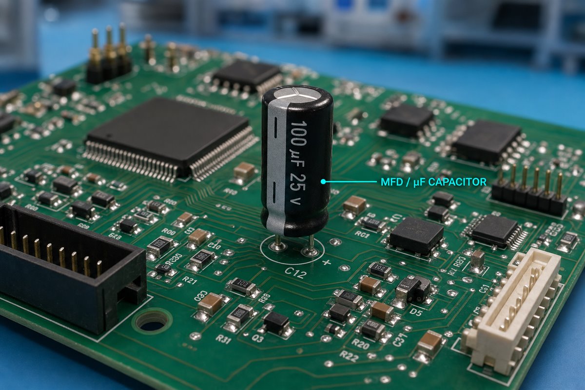
In conclusion, for most legacy capacitor markings, MFD means microfarad, so MFD, µF, and uF normally describe the same capacitance value. However, lowercase mF means millifarad and is 1,000 times larger than µF. In PCBA manufacturing, accurate capacitance, voltage, polarity, footprint, and soldering information is essential for preventing incorrect component substitutions and assembly failures.
For PCB and PCBA projects, the real risk is not only understanding the unit. A capacitor must also match the required voltage rating, tolerance, polarity, package, footprint, temperature rating, ESR, ripple current, and soldering process. EBest Circuit (Best Technology) helps customers review capacitor information during BOM sourcing, PCB fabrication, SMT assembly, inspection, and production preparation.
If your project includes capacitor value questions, legacy MFD markings, BOM substitutions, polarity concerns, or PCBA assembly requirements, you can send your Gerber files, BOM, CPL, assembly drawing, or project notes to sales@bestpcbs.com. EBest Circuit’s engineering team can review the manufacturing and assembly details before production, so capacitor-related issues are found earlier instead of after SMT.