
A rigid-flex PCB manufacturer builds circuit boards that combine rigid FR4 sections and flexible polyimide sections into one laminated structure. For buyers, the real selection problem is not only whether a supplier can quote rigid-flex boards. It is whether the supplier can review stackup, bend area, coverlay, stiffener, copper weight, via placement, testing access, and assembly risk before fabrication starts.
This guide is written for engineers and sourcing teams comparing rigid-flex PCB manufacturers for prototype, pilot, and production projects. It uses verified Best Technology / bestpcbs process-capability records where specific values are stated, and it avoids unsupported claims about guaranteed yield, lead time, certifications, or one-size-fits-all pricing.
Rigid-Flex PCB Manufacturer at a Glance
A strong rigid-flex PCB manufacturer should understand the mechanical and electrical behavior of both rigid and flexible areas. The supplier must treat the board as one connected structure, not as a normal rigid PCB with a flexible tail added late in the process.
| Decision area | What the manufacturer should review | Why it affects the order |
|---|---|---|
| Stackup | Rigid layers, flex layers, adhesive or adhesiveless core, coverlay, PP and rigid material | Controls thickness, impedance, bend reliability and cost. |
| Bend zone | Flex width, bend direction, copper pattern, via-free area and stiffener edge | Prevents cracking, delamination and installation failure. |
| Fabrication limits | Line/space, drilling, annular ring, pad size, impedance tolerance and test pad spacing | Determines whether the design can be built repeatably. |
| Assembly and test | Panel support, component placement, E-test, inspection access and functional test plan | Reduces handling damage and late rework. |
Is Your Rigid-Flex PCB Project Being Delayed by Bend and Stackup Risks?
Rigid-flex buyers often run into trouble when bend areas, stiffeners, coverlay, vias and assembly handling are not reviewed early.
| Customer Pain Point | Project Risk | How bestpcbs Helps |
|---|---|---|
| Bend radius or dynamic flex area is not clearly defined | Copper fatigue, cracked traces or short flex life can appear after installation | bestpcbs reviews bend areas, layer structure and mechanical notes before quoting so the project is not treated like a rigid PCB. |
| Vias or components are too close to flex transition zones | The board can fail during bending, handling or assembly | bestpcbs checks layout risk around transition zones, stiffeners and connector areas during DFM review. |
| Material and copper choices are not matched to flex use | The design may become too stiff or unreliable in the flex region | bestpcbs asks for application, bend type and stackup expectations before confirming material and process direction. |
| Assembly handling is not considered | Rigid-flex boards can be damaged by fixture, soldering or connector stress | bestpcbs reviews BOM, CPL, assembly drawings and handling notes together with the fabrication data. |
Buyer Priorities When Choosing a Rigid-Flex PCB Manufacturer
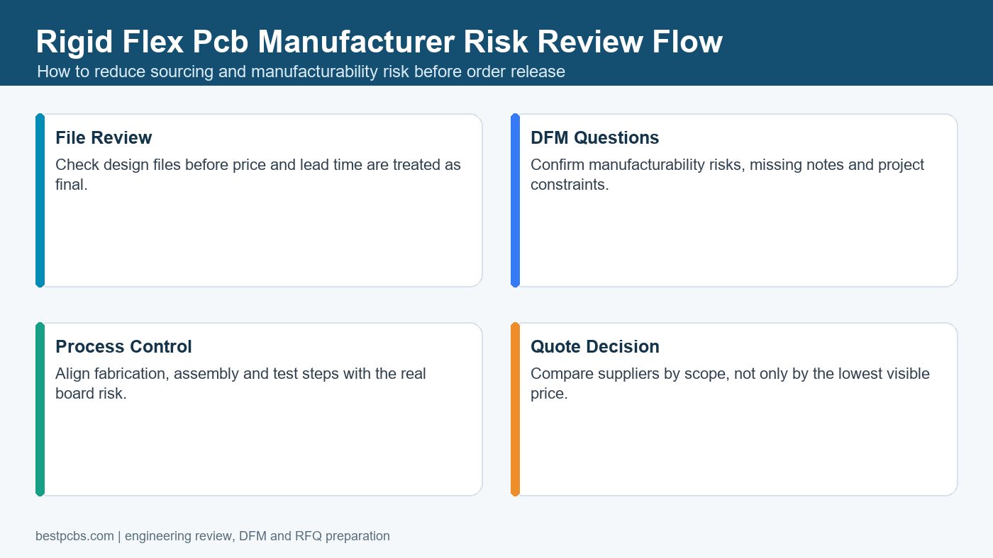
Rigid-flex PCB buyers need more than a supplier name; they need proof that the manufacturer can review stackup, bend areas, materials, drilling, lamination and assembly constraints before quoting. A weak review can lead to cracked flex zones, unclear transition areas, poor connector placement or late rework.
Before sending an RFQ, confirm whether the supplier can check bend radius, coverlay openings, stiffener requirements, via placement near flex areas, assembly handling and test expectations. This keeps the conversation focused on manufacturability rather than a generic board price.
Rigid-Flex PCB Capabilities to Confirm First
Before selecting a rigid-flex PCB manufacturer, confirm the layer range, flex position, board thickness, flex width, panel size, material system, impedance control and test access. These are the areas most likely to change feasibility, price or schedule.
| Capability item | Verified bestpcbs capability reference | RFQ note |
|---|---|---|
| Rigid-flex layer count | 2-20 layers for rigid-flex boards; HDI rigid-flex is project-dependent. | Send the full stackup and note buried/blind via needs. |
| Flex layer position | Outer or middle flex layer positions are listed in the capability record. | Mark bend areas clearly in the mechanical drawing. |
| Finished board thickness | 0.3-3.0 mm is listed for rigid-flex boards. | State rigid area thickness and flex area constraints separately. |
| Minimum flex width | 2.0 mm is listed for flex width and flex width between rigid sections. | Narrower or unusual geometry needs engineering review. |
| Panel size | Typical rigid-flex max panel sizes are listed around 210 x 1000 mm, with special cases needing review. | Send final outline and panelization expectations. |
| Impedance tolerance | +/-10% is listed in the rigid-flex capability sheet. | Provide controlled-impedance nets and target values. |
Rigid-Flex Stackup Review Before Quote
Rigid-flex stackup review should happen before a quote is finalized because material choices, flex location, copper weight and HDI structure change both manufacturability and cost. A quote based only on Gerbers may miss important mechanical assumptions.
Bestpcbs capability records include adhesive and adhesiveless flexible cores, PI thickness ranges, copper weights, coverlay, thermosetting adhesive, PI stiffener, 3M tape, low-flow PP, normal FR4 materials and special rigid materials that require procurement confirmation. In practice, the RFQ should state whether the flex area is designed for dynamic bending, limited bending during installation, or only space-saving interconnection.
Materials a Rigid-Flex PCB Manufacturer May Need to Source
Rigid-flex material choice affects bend reliability, thickness, copper adhesion, impedance and procurement risk. Buyers should not assume every PI core, coverlay, stiffener or high-frequency laminate is immediately available.
| Material group | Examples confirmed in capability records | Buyer action |
|---|---|---|
| Flexible core | Shengyi adhesive and adhesiveless PI core options; selected Panasonic, DuPont and Thinflex options are also listed. | Ask whether special materials have MOQ or longer purchasing time. |
| Coverlay | Shengyi SF305C series and TaiFlex / DuPont coverlay options are listed. | Define openings, bend zones and solderable pads clearly. |
| Stiffener and adhesive | PI stiffener options and 3M tape examples are listed. | Mark stiffener material, thickness and location in drawings. |
| Rigid materials | Normal FR4 options are listed, with selected high-frequency materials noted as special cases. | Do not substitute high-frequency laminate without impedance review. |
Bend Area and Mechanical Design Checks
The bend area is where many rigid-flex PCB failures begin, so the manufacturer should review copper routing, via placement, stiffener edges and rigid-flex transition clearance. A design that passes electrical CAD checks can still fail mechanically.
- Keep vias, plated holes and sharp copper transitions away from active bend areas.
- Use rounded traces and avoid abrupt width changes in the flex section.
- Mark whether bending is repeated in use or only occurs during installation.
- Separate rigid-section thickness requirements from flex-section requirements.
- Confirm clearances around the rigid-flex connection area before release.
Line Width, Spacing, Pads and Drilling Limits
Fine-line rigid-flex fabrication is possible, but line width, spacing, copper thickness and drilling requirements must be checked against the exact stackup. A single minimum number is not enough because 18 um, 35 um and 70 um copper do not behave the same way.
The rigid-flex capability record lists examples such as 3/3 mil inner line/space before compensation for 18 um finished copper under normal conditions, with tighter special cases requiring confirmation. It also lists 4-5 mil minimum E-test pad spacing under normal conditions and 4 mil for special cases. Use these as RFQ discussion points, not as a substitute for engineering review of the final data.
HDI and Controlled-Impedance Rigid-Flex Projects
HDI rigid-flex and controlled-impedance rigid-flex projects need more evidence than a simple capability claim. They require stackup control, laser drilling review, buried or blind via assumptions, reference-plane continuity and test strategy.
Bestpcbs records include HDI-related rigid-flex capability notes and +/-10% impedance tolerance. If the design includes high-speed signals, antennas, camera modules, medical electronics, compact connectors or dense BGAs, send impedance targets, allowed tolerance, reference layers, via structures and expected test coupons with the RFQ.
Cost Drivers in Rigid-Flex PCB Manufacturing
Rigid-flex PCB cost is driven by layer count, material system, panel utilization, HDI features, flex complexity, testing, special procurement and assembly handling risk. It is rarely comparable to a standard rigid PCB quote.
| Cost driver | Why it matters | How to control it |
|---|---|---|
| Layer and stackup complexity | More lamination and registration control are needed. | Use only the flex and HDI complexity the product really needs. |
| Special materials | MOQ and procurement time can change price. | Ask for approved alternates early. |
| Bend-zone risk | Mechanical failures cause scrap and rework. | Give bend radius, use condition and enclosure constraints. |
| Testing scope | E-test, impedance and functional checks require setup. | Define acceptance criteria in the RFQ. |
Prototype vs Production Rigid-Flex Orders
Prototype rigid-flex orders should focus on proving stackup, bend behavior, assembly fit and test access before scaling to production. Production orders need repeatability, material control and clear change management.
For prototype projects, send the mechanical installation context and mark what must be tested. For production, include revision control, approved material alternates, packaging requirements, inspection records and whether assembly will be handled by the same supplier. If assembly is part of the scope, the PCBA and PCB assembly service page is a relevant internal reference.
How to Compare Rigid-Flex PCB Manufacturers
Compare rigid-flex PCB manufacturers by their review process, material transparency, engineering questions and test planning, not only by the lowest quote. A supplier that asks better questions early may prevent a more expensive failure later.
- Do they ask for bend area, stackup and mechanical installation details?
- Do they explain which materials are standard and which require procurement confirmation?
- Can they review rigid-flex transition clearance and via placement?
- Can they support controlled impedance or HDI when the design requires it?
- Do they provide a clear RFQ assumption list before production?
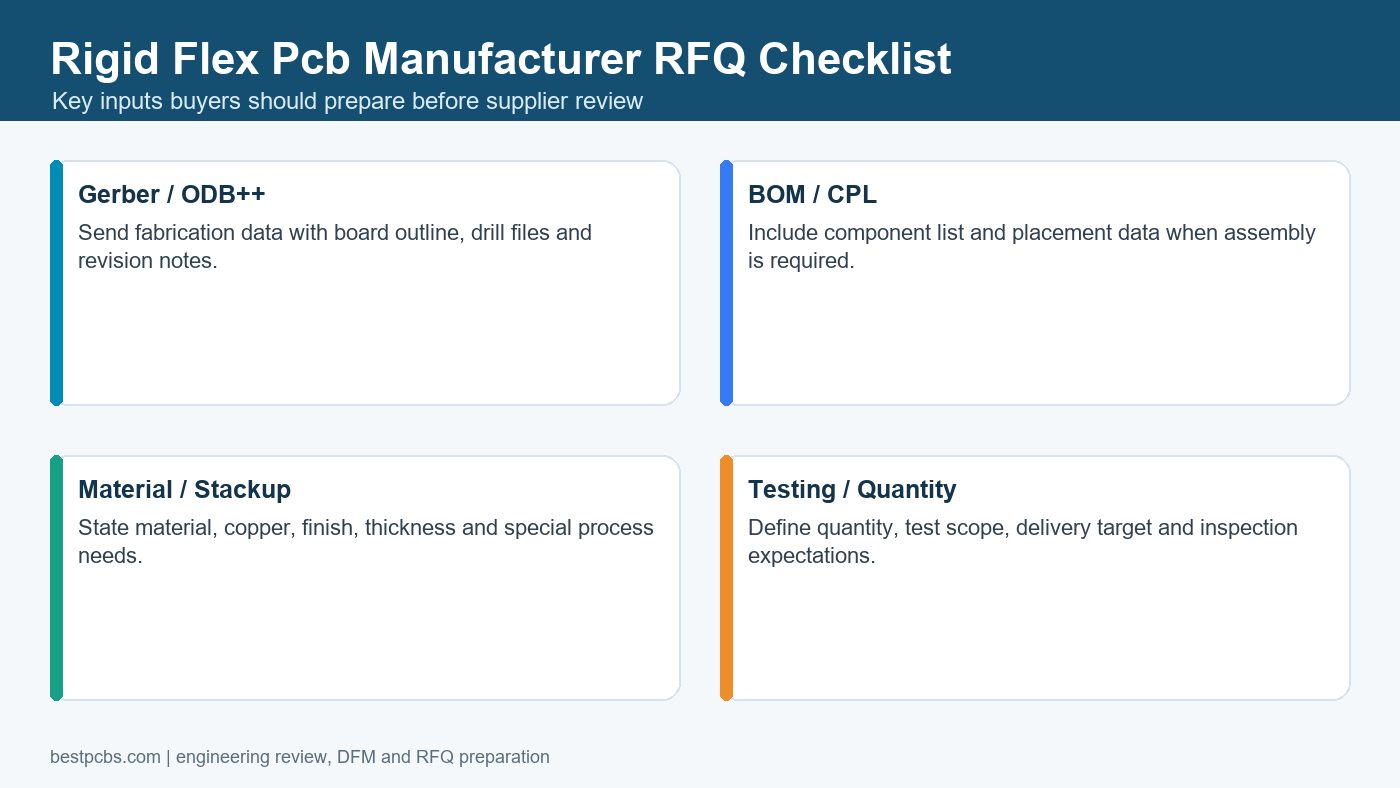
RFQ File Checklist for Rigid-Flex PCB Projects
A complete RFQ package helps a rigid-flex PCB manufacturer quote the real project instead of guessing at mechanical and material assumptions. Missing files usually lead to slower quoting or later price changes.
| RFQ item | Why it is needed |
|---|---|
| Gerber or ODB++ | Defines copper, mask, coverlay openings, outline and fabrication data. |
| Stackup drawing | Shows rigid layers, flex layers, PI core, adhesive, PP and rigid material. |
| Mechanical drawing | Defines bend area, stiffeners, thickness zones, slots and outline tolerance. |
| Drill and via files | Clarifies PTH, blind vias, buried vias, slots and plated features. |
| Impedance requirements | Defines target impedance, tolerance and controlled nets. |
| BOM, CPL and assembly notes | Needed if the quote includes assembly or turnkey PCBA. |
Internal Resources for Rigid-Flex Buyers
Buyers can reduce RFQ uncertainty by reviewing related rigid-flex, flex material and design resources before sending files. The most useful internal references are the Rigid Flex Circuit capability page, the newer flex PCB manufacturer guide, the rigid-flex PCB materials guide, and the custom flex PCB design checklist.
These pages support different parts of the decision: capability overview, supplier selection, material planning and bend-zone design checks. Use them together instead of treating rigid-flex sourcing as a one-page quote request.
Common Rigid-Flex Sourcing Mistakes
Common mistakes include treating rigid-flex as a standard rigid PCB, hiding bend requirements, omitting stackup data, using unsupported material assumptions and comparing quotes with different test scopes. These issues can make a cheap quote more expensive after engineering review.
- Do not send only Gerbers when the board has controlled bend zones.
- Do not assume every supplier uses the same PI, coverlay, adhesive or stiffener material.
- Do not place vias or plated holes near the rigid-flex transition without review.
- Do not ignore assembly handling if components are close to the flex area.
- Do not publish aggressive lead-time or price expectations until materials are confirmed.
Frequently Asked Questions About Rigid-Flex PCB Manufacturers
What does a rigid-flex PCB manufacturer do?
A rigid-flex PCB manufacturer fabricates boards that combine rigid PCB sections and flexible circuit sections in one interconnected structure. The supplier should review both electrical and mechanical requirements.
Is rigid-flex PCB more expensive than normal rigid PCB?
Usually yes, because rigid-flex boards require more stackup planning, material control, lamination accuracy, bend-zone review and testing. The exact cost depends on the design and RFQ data.
What files are needed for a rigid-flex PCB quote?
Send Gerber or ODB++, drill data, stackup, mechanical drawing, bend area notes, material requirements, impedance targets, quantity and any assembly files such as BOM and CPL.
Can rigid-flex PCB use HDI features?
Yes, but HDI rigid-flex must be reviewed against stackup, laser drilling, buried or blind via structure, impedance and test requirements. It should not be quoted from a simple keyword claim alone.
Final RFQ Recommendation
Choose a rigid-flex PCB manufacturer that reviews the stackup, bend zone, materials, via placement, testing and assembly scope before quoting. A careful review at the RFQ stage is usually cheaper than discovering a bend, material or registration problem after fabrication starts.
For a rigid-flex PCB quotation, send your Gerber or ODB++ files, stackup, mechanical drawing, bend area notes, material preferences, impedance requirements, quantity, surface finish, assembly files if needed, testing requirements and target lead time to sales@bestpcbs.com. The Best Technology / bestpcbs team can review the package and identify which manufacturing assumptions need confirmation before prototype, pilot or production release.