

The difference between inverter and converter is a common question in power electronics. People often search for it when they compare solar systems, RV power setups, UPS units, EV systems, battery storage, chargers, and industrial power products.
At first, the two words sound similar. Both devices handle electrical power. Also, both are used in modern electronic systems. However, they do not do the same job.
An inverter usually converts DC power into AC power. A converter is a broader device. It can change power from one form to another. For example, it may convert AC to DC, DC to DC, AC to AC, or DC to AC.
In simple terms, an inverter has a more specific role. A converter covers a wider group of power circuits.
This difference is useful to know. It affects product design, PCB layout, heat control, component choice, and PCBA testing. Therefore, engineers, buyers, and product teams should understand the basics before they choose or build a power device.
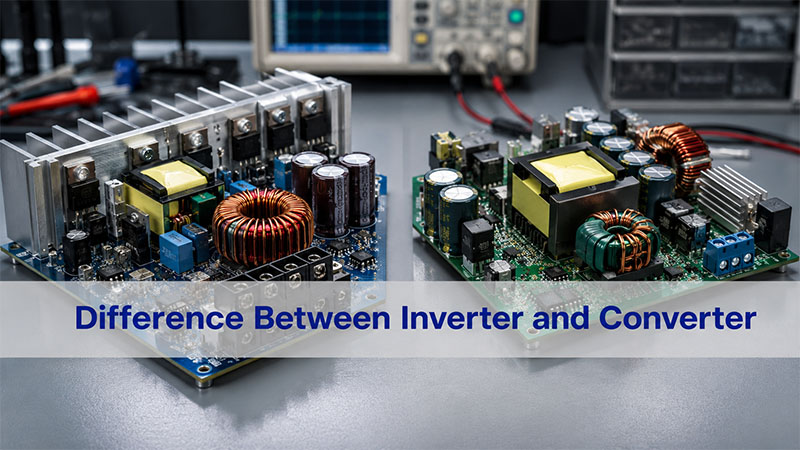
What Is the Difference Between Inverter and Converter?
The main difference between an inverter and a converter is the type of power change they perform.
An inverter converts DC power into AC power. DC means direct current. In DC power, the current flows in one direction. Batteries, solar panels, and many energy storage systems provide DC power.
AC means alternating current. In AC power, the current changes direction again and again. Homes, factories, grid systems, and many machines use AC power.
A converter changes electrical power from one form to another. It may change voltage level, current type, frequency, or waveform. Because of this, converter is a wider term.
Simple Explanation
Here is the easiest way to remember it:
An inverter usually changes DC to AC. A converter can change power in several ways.
For example, a solar panel produces DC power. However, most home appliances need AC power. Therefore, a solar system needs an inverter to run those appliances.
By comparison, a phone charger works in another way. It takes AC power from a wall outlet. Then, it converts that power into low-voltage DC power for the phone battery. So, the charger is a converter.
In short, the two devices are related. However, they are not the same in everyday use.
Inverter vs Converter: Quick Comparison Table
A table can make the difference easier to understand.
| Item | Inverter | Converter |
|---|---|---|
| Basic Function | Converts DC power to AC power | Changes power from one form to another |
| Common Power Direction | DC to AC | AC to DC, DC to DC, AC to AC, or DC to AC |
| Typical Input | Battery, solar panel, or DC bus | AC mains, battery, DC source, or another power stage |
| Typical Output | AC voltage | AC or DC voltage |
| Common Applications | Solar inverter, UPS, RV inverter, EV inverter, motor drive | Charger, adapter, power supply, DC-DC module, voltage converter |
| Key Components | MOSFET, IGBT, gate driver, transformer, capacitor, filter | Diode, rectifier, regulator, transformer, inductor, capacitor, IC |
| PCB Design Focus | Heat, high current, EMI, switching loops | Voltage stability, ripple control, isolation, efficiency |
| Common User Question | “How do I turn battery power into AC power?” | “How do I change voltage or current type?” |
In short, an inverter has a clear DC-to-AC function. A converter, however, can describe many kinds of power conversion circuits.
What Is an Inverter?
An inverter is an electrical device that converts DC power into AC power.
This is important because many power sources provide DC power. Batteries, solar panels, fuel cells, and DC bus systems are common examples. However, many appliances and machines need AC power. Therefore, an inverter connects a DC source to an AC load.
Common Inverter Applications
Inverters are used in many products, such as:
- Solar inverters
- RV inverters
- UPS inverters
- EV traction inverters
- Motor drive inverters
- Battery energy storage inverters
- Industrial frequency inverters
- Portable power station inverters
For example, a battery energy storage system stores DC power. When the user needs AC output, the inverter changes that stored energy into usable AC power.
Main Inverter Components
Inside an inverter, power components switch very fast. These parts may include MOSFETs or IGBTs. The right choice depends on voltage, current, power level, and switching speed.
A control circuit sends signals to the switching parts. Then, filters help shape the output. As a result, the final AC output becomes suitable for the connected load.
From a PCB point of view, this fast switching needs careful design. The board must carry current safely. Also, it must move heat away from key components. In addition, it must reduce noise from high-speed switching.
What Is a Converter?
A converter is a power device that changes electrical power from one form to another.
The word “converter” is broad. In consumer products, it often means an adapter or charger. In power electronics, it may mean an AC-DC converter, DC-DC converter, AC-AC converter, or DC-AC converter.
Common Converter Types
| Converter Type | Function | Example |
|---|---|---|
| AC-DC Converter | Converts AC to DC | Phone charger, power adapter, LED driver |
| DC-DC Converter | Converts one DC voltage to another | Battery electronics, automotive modules |
| AC-AC Converter | Changes AC voltage or frequency | Voltage regulator, frequency control system |
| DC-AC Converter | Converts DC to AC | Inverter, solar inverter, UPS inverter |
Because the term is broad, an inverter can technically be one type of converter. However, people usually use the two words differently.
In daily use, “inverter” often means DC-to-AC conversion. Meanwhile, “converter” often means AC-to-DC or DC-to-DC conversion.
Why Converters Matter
Converters are used almost everywhere in electronics. For instance, laptops, medical devices, communication systems, LED lighting, industrial controllers, and automotive modules all need power conversion.
A converter board may look small. Still, it can be complex. It needs stable output, low ripple, good feedback routing, and proper heat flow. Therefore, both circuit design and PCB layout matter.
How Does an Inverter Work?
An inverter works by switching DC power very quickly. Through this switching process, it creates an AC output waveform.
Most modern inverters use PWM, or pulse width modulation. PWM controls the width of electrical pulses. As a result, the circuit can shape the output waveform more accurately.
Basic Working Steps
A simple inverter process includes five steps:
- DC input enters the circuit
The input may come from a battery, solar panel, DC bus, or energy storage system. - Switching parts create pulses
MOSFETs or IGBTs turn on and off at high speed. - The control circuit manages timing
A driver and controller set the switching pattern, output frequency, and protection logic. - Filters improve the waveform
Inductors, capacitors, and sometimes transformers reduce noise. - AC output powers the load
Finally, the inverter supplies AC power to appliances, motors, or other equipment.
Why PCB Layout Is Important
Inverter circuits often handle high current. They also switch very fast. Therefore, the PCB layout must be clean and compact.
For example, long switching loops can increase noise. Poor heat paths can raise component temperature. In addition, weak grounding can affect waveform quality.
Because of this, inverter PCB design should consider current path, thermal relief, EMI control, creepage, clearance, and component placement from the beginning.
How Does a Converter Work?
A converter works by changing voltage level, current type, or power form. The exact method depends on the converter type.
Some converters use rectification. Others use switching, regulation, filtering, or transformers. In many power products, several methods work together.
AC-DC Converter
An AC-DC converter takes AC input and turns it into DC output.
First, a rectifier changes AC into pulsating DC. Then, capacitors and regulators smooth and control the output. As a result, the circuit provides a more stable DC voltage.
This type of converter is common in chargers, adapters, LED drivers, and power supplies.
DC-DC Converter
A DC-DC converter changes one DC voltage into another DC voltage. It may step voltage down. It may also step voltage up. In some designs, it can also provide isolation.
Common DC-DC converter types include:
- Buck converter
- Boost converter
- Buck-boost converter
- Flyback converter
- Forward converter
- LLC resonant converter
For example, an EV may use a DC-DC converter. It can reduce high battery voltage to a lower voltage for control electronics.
Converter PCB Design Needs
Converter PCB design often focuses on stable output. Therefore, engineers must check feedback routing, ripple control, grounding, magnetic component placement, and heat flow.
Even a small layout issue can affect output quality. So, early PCB review is helpful before production.
Power Inverter vs Power Converter: What Is the Difference?
A power inverter converts DC power into AC power. A power converter changes power form, voltage level, or current type.
The difference becomes clearer in real systems.
For example, a battery system may use both devices. The battery stores DC power. If the product needs AC output, it needs a power inverter. However, if the product needs a lower DC voltage for control circuits, it may need a DC-DC power converter.
Power Flow Matters
Instead of looking only at the product name, engineers should check the power flow.
Ask these questions:
- What is the input voltage?
- Is the input AC or DC?
- What output voltage is needed?
- Is the output AC or DC?
- How much current is required?
- Does the circuit need isolation?
- How much heat will it produce?
- What safety standards apply?
Once these points are clear, the right design choice becomes much easier.
RV Inverter vs Converter: What Is the Difference?
In RV power systems, an inverter and a converter usually do opposite jobs.
An RV inverter converts battery DC power into AC power. This allows users to run AC appliances when shore power is not available. For example, it may power a TV, laptop charger, coffee maker, or microwave, depending on its rating.
An RV converter usually converts AC shore power into DC power. It can charge the RV battery. It can also supply 12V DC loads. These loads may include lights, fans, control panels, and small DC devices.
Easy RV Explanation
The simple rule is:
An RV inverter helps the battery power AC devices. An RV converter helps AC power charge the battery and support DC loads.
Some RV systems use inverter-chargers. These units combine both functions. Therefore, they can convert DC to AC and also convert AC to DC for battery charging.
This is why many users feel confused. The product name may include inverter, converter, charger, or inverter-charger. However, the real difference depends on the power direction.
Converter vs Inverter vs Rectifier vs Transformer
Converter, inverter, rectifier, and transformer are related terms. However, they do different jobs.
| Term | Basic Meaning | Common Function |
|---|---|---|
| Converter | Broad power conversion device | Changes voltage, current type, or power form |
| Inverter | DC-to-AC device | Converts battery or DC bus power into AC |
| Rectifier | AC-to-DC circuit | Converts AC into DC |
| Transformer | Magnetic energy transfer device | Steps AC voltage up or down and may provide isolation |
Rectifier
A rectifier converts AC into DC. It is often used inside an AC-DC converter. After rectification, the circuit usually needs filtering and regulation.
Transformer
A transformer transfers energy through magnetic coupling. It can step AC voltage up or down. Also, it can provide isolation between circuits.
However, a transformer does not convert AC into DC by itself.
Converter
A converter may contain rectifiers, transformers, regulators, switching parts, control ICs, and filters. Therefore, it is the broadest term in this group.
A practical way to remember the difference is:
- Rectifier: AC to DC
- Inverter: DC to AC
- Transformer: AC voltage change and isolation
- Converter: broader power conversion system
Where Are Inverters and Converters Used?
Inverters and converters are used in many industries. Any product that needs charging, voltage matching, motor control, or stable power may use one or both.
Solar Energy Systems
Solar panels generate DC power. Therefore, solar systems use inverters to convert DC into AC for homes, businesses, or grid connection.
In addition, DC-DC converters may help with battery charging or power optimization.
Battery Energy Storage
Battery systems store DC power. However, many loads need AC power. As a result, energy storage systems often use both inverters and converters.
Electric Vehicles
EVs use traction inverters to drive motors. Also, they use DC-DC converters to power low-voltage electronics from the high-voltage battery pack.
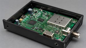
UPS Systems
A UPS may include rectification, battery charging, DC storage, and inversion. Therefore, both converter and inverter functions may appear in one system.
Industrial Motor Control
Motor drives use inverter stages to control speed and torque. These systems require stable switching, strong heat control, and good EMI performance.
Medical and Communication Equipment
Medical devices need stable and low-noise power. Communication systems also need efficient DC-DC conversion. In both cases, reliability is very important.
How Do Inverter and Converter Differences Affect PCB and PCBA Design?
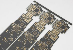
The function of an inverter or converter directly affects PCB design. It also affects material choice, copper thickness, component placement, heat control, and testing.
Inverter PCB Design Focus
For inverter PCB design, engineers often check:
- High-current paths
- Switching loops
- MOSFET or IGBT placement
- Gate driver routing
- DC bus capacitor layout
- EMI control
- Creepage and clearance
- Heat dissipation
- Output filtering
- Protection circuits
Because inverters switch high current at high speed, layout quality is very important. For example, poor routing can increase noise. Also, weak heat paths can shorten product life.
Converter PCB Design Focus
For converter PCB design, engineers usually focus on:
- Voltage regulation
- Feedback loop routing
- Ripple reduction
- Transformer or inductor placement
- Isolation spacing
- Grounding strategy
- Component derating
- Thermal vias
- Output filtering
- Efficiency
Although converter boards may be compact, they still need careful design. A noisy feedback trace can affect stability. Poor grounding can also reduce output quality. Therefore, layout review is useful before mass production.
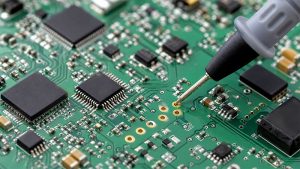
PCBA Manufacturing Considerations
Both inverter and converter PCBAs need controlled manufacturing. For example, solder quality, component polarity, insulation spacing, copper thickness, and test coverage all matter.
In high-power products, the PCB is more than a base for parts. It is also part of the electrical and thermal system.
What Should Engineers Check Before Manufacturing Inverter or Converter PCBAs?
Before manufacturing an inverter or converter PCBA, engineers should review the full design. This includes electrical, thermal, mechanical, and process details.
Electrical Ratings
First, confirm the input voltage, output voltage, current, power level, surge condition, and load range. These ratings affect trace width, component choice, insulation spacing, and test method.
Copper Thickness and Current Path
High-current boards may need wider traces, heavy copper, copper pours, bus bar structures, or special thermal paths. Therefore, current path review should happen early.
PCB Material
Many control boards use FR4. However, high-power applications may need high-Tg FR4, heavy copper PCB, metal core PCB, or ceramic PCB.
The right choice depends on voltage, current, temperature, and product life requirements.
Creepage and Clearance
Power circuits need safe spacing between high-voltage areas. This is especially important for isolated designs, primary and secondary sides, and user-accessible products.
Thermal Management
MOSFETs, IGBTs, diodes, transformers, inductors, and resistors may generate heat. Therefore, the design may need thermal vias, copper planes, heat sinks, or enclosure contact areas.
EMI Control
Fast switching can create electromagnetic noise. To reduce EMI, engineers should use short loops, proper grounding, filtering, shielding, and careful component placement.
BOM and Component Supply
Power semiconductors, capacitors, magnetic parts, and control ICs should be checked for availability. In addition, approved alternatives can help reduce supply risk.
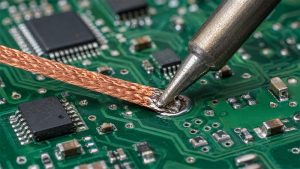
Assembly and Testing
Power boards may need AOI, X-ray, ICT, functional testing, burn-in testing, hipot testing, load testing, and thermal testing. As a result, the test plan should be confirmed before production.
For inverter PCBAs and converter PCBAs, EBest Circuit can support PCB fabrication, PCBA assembly, DFM review, BOM sourcing, component procurement, functional testing, and production-quality control. Our team supports power electronics projects for industrial control, energy systems, automotive electronics, medical devices, communication equipment, and other high-reliability applications.
In conclusion, the difference between inverter and converter becomes clear when you look at the power direction. An inverter usually converts DC to AC. A converter is a broader device. It can change electrical power in many ways, such as AC to DC, DC to DC, AC to AC, or DC to AC.
In practical systems, both may appear together. For example, solar energy systems, RV power systems, EVs, UPS units, industrial drives, and battery storage products may use both inverter and converter circuits. For engineers, this difference affects much more than product naming. It influences circuit design, PCB layout, material selection, heat control, component sourcing, assembly process, and testing strategy.
If your project involves inverter PCBAs, converter PCBAs, power supply boards, high-current control boards, or power electronics manufacturing, EBest Circuit can support the process from DFM review and PCB fabrication to BOM sourcing, SMT assembly, functional testing, and production delivery. For technical support or project evaluation, pls feel free to contact us via sales@bestpcbs.com.
FAQs About the Difference Between Inverter and Converter
What Is the Main Difference Between an Inverter and a Converter?
The main difference is the power direction. An inverter usually converts DC power into AC power. A converter changes electrical power from one form to another, such as AC to DC, DC to DC, AC to AC, or DC to AC.
Is an Inverter a Type of Converter?
Yes. Technically, an inverter can be seen as a type of converter because it changes DC power into AC power. However, in common use, “inverter” usually means DC-to-AC conversion, while “converter” often means AC-to-DC or DC-to-DC conversion.
What Is the Difference Between a Power Inverter and a Power Converter?
A power inverter converts DC input into AC output. A power converter may change voltage level, current type, or power form. For example, chargers, adapters, power supplies, and DC-DC modules are power converters.
What Is the Difference Between an RV Inverter and Converter?
An RV inverter uses battery DC power to supply AC appliances. An RV converter takes AC shore power and changes it into DC power for battery charging and 12V DC loads.
What Is the Difference Between Converter and Inverter and Rectifier?
A converter is a broad power conversion device. An inverter converts DC to AC. A rectifier converts AC to DC. In many power systems, rectifiers and inverters can both be parts of a larger converter system.
What Is the Difference Between Inverter and Frequency Converter?
An inverter converts DC power into AC power. A frequency converter changes the frequency of AC power, often for motor control. Many frequency converters include both rectifier and inverter stages inside the system.
Do Inverters and Converters Use the Same PCB Components?
They may share some parts. For example, both may use MOSFETs, capacitors, inductors, transformers, diodes, sensors, and control ICs. However, their PCB layout, heat design, feedback routing, and test needs may be different.
Can One Device Work as Both an Inverter and a Converter?
Yes. Some systems combine both functions. For example, an inverter-charger can convert DC battery power into AC output. It can also convert AC input into DC power for battery charging.
You may also like

Tags: Difference Between Inverter and Converter, Inverter Converter PCBA, Inverter vs Converter, Power Electronics PCB