





If a thicker PCB busbar does not fix voltage drop, measure the straight copper and each connection separately. A larger cross section lowers the bar’s bulk resistance, but it does not remove contact resistance at bolts, press-fit transitions or board terminals. Fix the segment that consumes the budget, then repeat the hot test.

Busbar Joint Resistance
Busbar joint resistance is the electrical resistance of a connection between current-carrying parts, as observed over a defined measurement span. A reading across a joint often includes some adjoining copper. Put the sense points in the drawing so another engineer can reproduce what the number represents.
Consider a hypothetical low-voltage power board that misses an 8 mV path budget at 40 A. The route includes a short copper bar and two connections. The next revision should not add more copper until the test identifies where the drop occurs.
Copper Busbar PCB
A copper busbar can carry current separately from an etched board trace. The feed, contact and exit still need to carry the same current. A press-fit, bolted or soldered connection has its own construction and verification requirements. Do not generalize current or torque limits across connection types.
Draw the path from supply to load and mark the intended measurement spans. If the board uses an embedded busbar, check the transitions into and out of it as well as the main copper. The Best Technology embedded busbar design guide covers related construction choices.
Heavy Copper PCB
Compare a heavy copper PCB path and a busbar by their complete current paths. Heavy copper can avoid a separate mechanical interface over part of the route, but narrow necks, vias and terminals can still dominate. A bar offers a separate copper cross section while adding transitions that need qualification.
| Option | Check first |
| Heavy copper PCB | Narrowest trace, via bank and terminal |
| Board-mounted busbar | Straight bar and every attachment |
| Embedded busbar | Copper insert and board transitions |
Choose by drop, temperature, assembly and service requirements, not the nominal copper area alone.
Copper Busbar Resistance Calculator
Estimate only the uniform copper section with R = resistivity × length ÷ area. Use matching units. For an illustrative room-temperature copper resistivity of 0.0172 Ω·mm²/m, 0.050 m length and 20 mm² area, the bar is about 0.000043 Ω, or 43 µΩ. The estimate excludes both joints and nearby constrictions.
Use actual material, dimensions and operating temperature when the budget is tight. The calculated 43 µΩ is not a current rating or a measured property of the hypothetical assembly.
Busbar Voltage Drop Calculation
Convert each resistance to voltage drop with V = I × R. In the example, assume two measured-span resistances of 100 µΩ each, excluding the straight segment. At 40 A they account for 8.00 mV together. The 43 µΩ straight section adds 1.72 mV, so the full path is 9.72 mV and exceeds the illustrative 8 mV budget.
| Path segment | Resistance used | Drop at 40 A |
| Straight bar | 43 µΩ | 1.72 mV |
| Joint span A | 100 µΩ | 4.00 mV |
| Joint span B | 100 µΩ | 4.00 mV |
| Full path | 243 µΩ | 9.72 mV |
These are teaching inputs, not field results. Even doubling the bar area would leave about 8.86 mV if the two connections were unchanged.
Four Wire Resistance Measurement
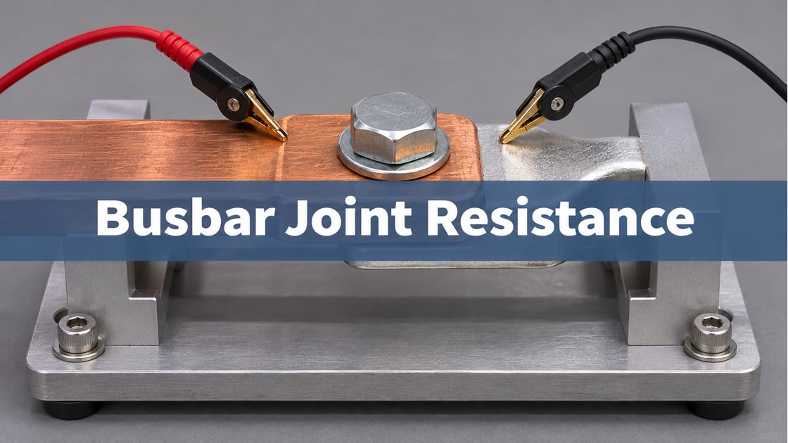
Use separate current and sense connections to reduce the influence of lead resistance. In a qualified low-energy resistance setup, place the sense contacts at the named points and use the instrument’s appropriate method. A two-wire reading can be dominated by test leads and contacts at this resistance scale.
At very small voltages, thermoelectric offsets can matter. Use a suitable measurement method, such as current reversal when the equipment and test procedure support it. Document what copper is inside each span and do not sum overlapping spans as separate resistances.
Busbar Temperature Rise Test
Repeat the temperature and voltage checks in the approved operating setup. At 40 A and 100 µΩ, each illustrative joint span dissipates I²R = 0.16 W. Whether that creates a hot spot depends on the local heat path, contact area, airflow and enclosure. A room-temperature resistance pass does not establish operating temperature.
Measure at consistent points after the agreed dwell or steady-state condition. Use only a rated, guarded setup under the approved procedure. If the joint heats more than the bar, inspect its construction and nearby constrictions before adding copper to the straight section.
Busbar Joint Resistance Test
Release the design when the assembled path meets the specified voltage and temperature limits and the connection can be built repeatably. Record joint type, materials, assembly instructions, sense locations, current and thermal conditions. For bolted joints, follow the approved hardware and torque specification rather than a general table.
After a correction, rerun the same segment and full-path checks. If voltage drop is still above target, confirm whether the remaining loss moved to a different transition before selecting another design change.
Frequently Asked Questions
Does a thicker copper busbar fix every voltage-drop problem?
No. It lowers the resistance of the uniform copper segment, but contacts, vias and terminal transitions may account for most of the loss. Measure the sections separately and compare them with the path budget. Increase copper only when the measured or modeled bottleneck justifies it.
Where should voltage sense points go?
Place them at repeatable points that bracket the segment you intend to measure. Include the positions on a drawing and note any adjoining copper inside the span. Changing the points can change the apparent joint resistance even when the physical connection has not changed.
Can I use a standard two-wire multimeter for a micro-ohm joint?
A two-wire reading includes lead and contact resistance, which may be larger than the joint itself. Use a suitable four-wire method and instrument for the expected range. Verify the setup and its offset before interpreting small differences between two joints or two assembly revisions.
Can a good cold measurement rule out a hot joint?
No. Temperature, contact condition and the operating environment can change the result. Use the cold measurement to locate and compare segments, then perform the required operating-current thermal test in an approved setup. Check both voltage drop and temperature against their separate limits.
Why can two identical-looking joints read differently?
Contact preparation, hardware, fit, plating and assembly variation can change the interface. First verify that the sense spans and test conditions match. If the difference remains, compare the controlled build records and examine the actual joint rather than assuming the bar dimensions are wrong.
Should I increase bolt torque to lower resistance?
Use only the approved joint specification for that hardware and construction. Extra torque is not a general fix and may damage parts or change the interface. Review the contact surfaces, assembly method and approved limits with the process owner, then verify the corrected build.
Can I compare a press-fit joint directly with a bolted joint?
Compare them against the same product requirements and use equivalent measurement boundaries. The assembly controls and local geometry differ, so document what each reading includes. Check resistance, temperature and mechanical reliability for the actual connection rather than ranking the joining methods by name.
What evidence is useful for a PCB busbar review?
Send the bar and terminal drawings, current and drop limits, stackup, connection method and intended operating conditions. Include a marked sense-point map and any measured segment voltages. That lets the reviewer distinguish copper cross section, board transitions and joint behavior before recommending a change.
References
Discuss Your PCB Requirements
For a Best Technology fabrication review, send the current path drawing, busbar and terminal geometry, and your voltage and temperature limits to sales@bestpcbs.com. If you have measured drop, mark the actual sense points.
You may also like


Tags: Busbar Joint Resistance, Copper Busbar Drop, Four-Wire Joint Test, High Current PCB Connections