





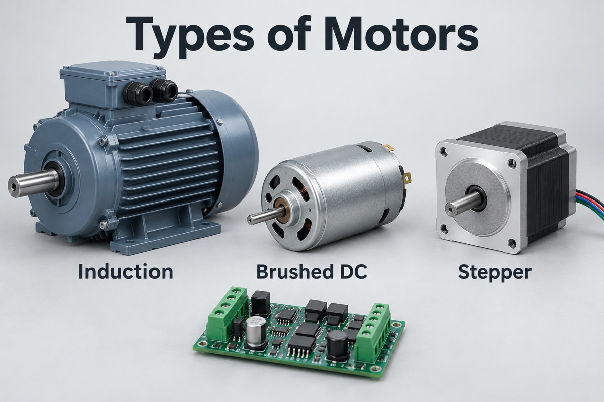
The main types of motors used in electrical equipment include brushed DC, brushless DC (BLDC), AC induction, synchronous, stepper and universal motors. Servo motors are also common, but “servo” describes a feedback-controlled motion system rather than one electromagnetic construction. Choosing between them starts with the required torque, speed, positioning accuracy and power supply—not simply whether a product runs from a battery or the mains.
This guide focuses on electric motors and the electronics that drive them. Hydraulic and pneumatic motors use different energy sources and fall outside this comparison.
Key Takeaways
- Electric motors convert electrical energy into motion; their construction, supply and control method are separate ways to classify them.
- Brushed DC motors use mechanical commutation. BLDC motors need electronic commutation and a compatible driver.
- Induction motors develop torque with slip; synchronous motors follow the rotating magnetic field at synchronous speed in steady operation.
- Servo is a control-system description, not an alternative to every AC or DC motor category.
- Steppers offer incremental positioning, but microstepping resolution does not guarantee equal positioning accuracy.
- Selection requires the torque–speed curve, acceleration, duty cycle and thermal conditions—not rated power alone.
- Motor driver PCB design must account for current paths, switching loops, heat, sensing and protection; assembly inspection does not replace loaded functional testing.
What Are the Main Types of Electric Motors?
The main electric motor types are brushed DC, BLDC, induction, synchronous, stepper and universal motors. Servo systems add feedback-controlled motion and can use several motor constructions, so they are listed separately below.
| Motor or system | Operating principle | Typical applications |
| Brushed DC | Brushes and a commutator switch rotor current | Small actuators, simple pumps, low-cost drives |
| BLDC | Electronic switching energizes stator windings around a permanent-magnet rotor | Fans, battery tools, compact pumps |
| AC induction | A rotating stator field induces rotor current | Conveyors, industrial pumps, ventilation |
| Synchronous | Rotor rotation stays synchronized with the stator field | Controlled industrial drives, traction, compressors |
| Stepper | Sequenced winding currents produce incremental rotation | Printers, dosing mechanisms, positioning stages |
| Universal | A series-wound commutator design operates on suitable AC or DC | Some corded tools and household appliances |
| Servo system | Feedback corrects motion against a command | Robot joints, CNC axes, packaging machines |
A gearmotor adds a gearbox to a motor; it is not a separate electromagnetic principle. Likewise, “linear” describes motion along a line rather than rotation. An AC synchronous motor can therefore also be part of a geared servo axis.
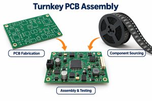
At EBest Circuit, we support the electronics behind these systems through PCB fabrication, component sourcing and PCB assembly services. For a motor controller, the manufacturing review starts with its power stage, board construction and assembly requirements—not with a claim that one PCB suits every motor.
How Do AC and DC Motor Classifications Differ?
AC and DC usually describe the electrical supply or the way a motor is driven, but modern electronic drives make that distinction less straightforward. A battery supplies DC, while an inverter can convert it into alternating phase currents for a synchronous motor.
Induction and synchronous machines are familiar AC categories. Brushed motors can connect to a suitable DC source, whereas BLDC motors require a commutating controller. Check the motor terminals, drive documentation and winding ratings rather than classifying a motor from the equipment’s input plug alone.
How Do Brushed DC and BLDC Motors Differ?
Brushed DC motors switch current mechanically; BLDC motors switch it electronically. Brushes simplify the external drive but introduce contact wear and electrical noise, while BLDC designs move the switching task into the controller.
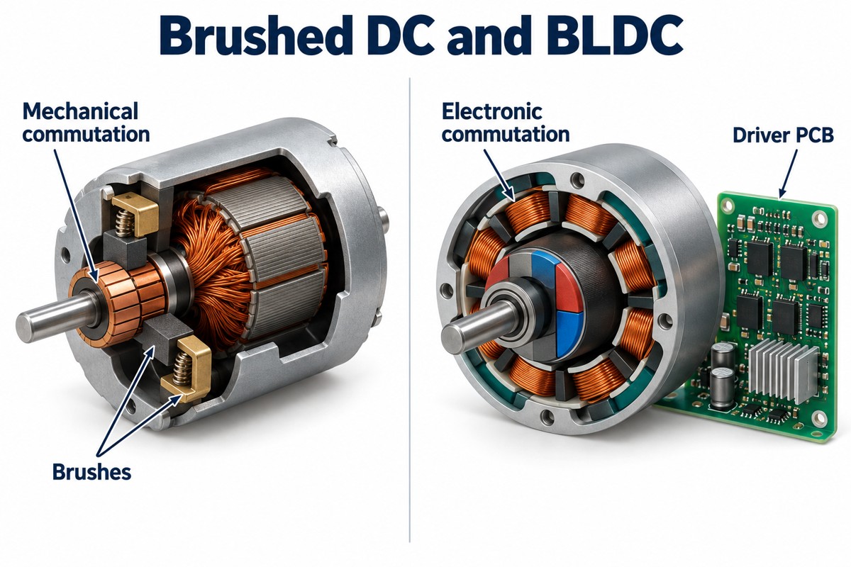
- Brushed DC: a single switching stage can provide one-direction speed control; an H-bridge supports reversal and controlled braking.
- BLDC: a typical three-phase drive uses three half-bridges. Rotor position can come from sensors or estimation, depending on the controller.
- Maintenance: eliminating brushes removes brush wear, but bearings, insulation and electronics still have operating limits.
BLDC and permanent-magnet synchronous motor (PMSM) terminology overlaps. BLDC commonly refers to trapezoidal back-EMF and block commutation, while PMSM often refers to sinusoidal operation. The actual motor and control algorithm matter more than the label on a product listing.
What Is the Difference Between Induction and Synchronous Motors?
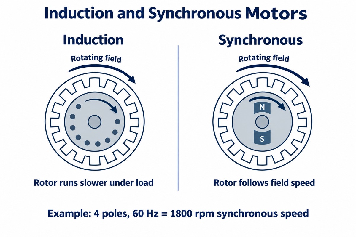
An induction motor’s rotor normally runs below the rotating field speed when producing motoring torque; a synchronous motor’s rotor follows that field speed in steady operation. The speed difference in an induction machine is called slip.
Synchronous speed is n = 120f/P, where n is rpm, f is electrical frequency in hertz and P is the number of poles. A four-pole motor at 60 Hz has a synchronous speed of 1,800 rpm. If an induction motor runs at 1,750 rpm under the stated load, its slip is approximately 2.8%; that is an illustrative operating point, not a universal rating.
Induction motors are practical for continuous industrial rotation. Permanent-magnet synchronous drives can offer efficient, compact controlled motion, but need a suitable starting and control arrangement. A variable-frequency drive changes electrical frequency; neither category is inherently limited to one shaft speed.
When Should You Choose a Stepper or Servo System?
Choose a stepper for incremental positioning within a known torque–speed envelope; choose a servo system when feedback-based error correction and dynamic response justify the additional control hardware. Load changes, acceleration and required settling time determine the better fit.
A common 1.8° stepper makes 200 full steps per revolution. With 16 microsteps per full step, the driver receives 3,200 step commands per revolution, but that does not establish 3,200 equally accurate mechanical positions. Friction, load torque and motor construction affect the result.
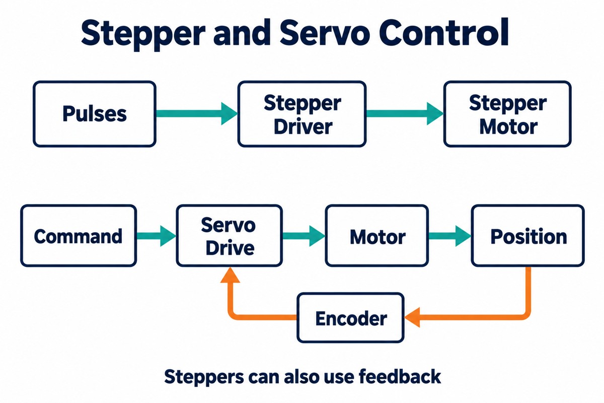
An open-loop stepper can lose position if the commanded motion exceeds available torque. A servo measures motion and adjusts its output, although it still needs tuning and suitable mechanical sizing. Closed-loop stepper products also exist, so “stepper means no feedback” is not a reliable rule.
Which Types of Motors Are Used in Common Applications?
Fans and pumps usually need sustained rotation, while robots and positioning equipment need controlled motion. Those different loads explain why equipment in the same industry may use several motor technologies.
- Types of motors used in robotics: geared brushed DC motors can drive simple mobile platforms; BLDC/PMSM servo systems suit controlled joints; steppers suit indexing and smaller positioning mechanisms.
- Types of motors in HVAC: induction motors appear in fans and pumps, while electronically commutated permanent-magnet motors support variable-speed blowers. Compressor motor selection depends on the compressor and drive architecture.
- Types of motors in cars: brushed and brushless motors serve auxiliary actuators, fans and pumps. Electric traction can use permanent-magnet synchronous or induction machines, among other architectures.
A motor suitable for a small robot wheel is not automatically suitable for a vertical lifting axis. Holding requirements, a mechanical brake and the consequences of losing power must be considered separately from normal running torque.
How Do You Select the Right Motor for a Load?
Select a motor whose continuous and peak torque cover the required speed, acceleration and duty cycle without exceeding its thermal limits. Rated wattage alone cannot show whether it will start the load or survive repeated stops.
- Define motion: required shaft speed, travel, acceleration and positioning accuracy.
- Calculate load torque: include friction, gravity, inertia and gearbox losses where applicable.
- Check the torque–speed curve: confirm both the continuous operating point and short-duration peaks.
- Match the drive: verify supply voltage, phase current, feedback interface and braking requirements.
- Check temperature and duty: use the manufacturer’s specified cooling and ambient conditions.
For a calculated example, a shaft delivering 2 N·m at 1,500 rpm produces about 314 W of mechanical power, using P = T × 2πn/60. Electrical input must be higher because the motor and drive have losses. Starting torque can still exceed this steady operating requirement.
How Does Motor Type Affect the Driver PCB?
Motor type determines the power-stage arrangement, current regulation and feedback interfaces on the driver PCB. A reversible brushed motor typically needs one H-bridge; a bipolar two-phase stepper needs two; a typical three-phase BLDC drive needs three half-bridges.
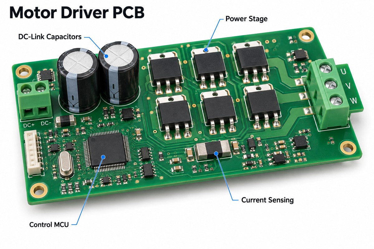
- Power routing: size copper paths and vias for RMS current, permissible heating and the actual stackup.
- Switching loops: place local decoupling near the switching stage and keep high-current loops compact.
- Sensing: route current-sense connections to avoid power-path voltage drops corrupting measurements.
- Protection: account for overcurrent, stalled operation, reverse supply and regenerated energy as the application requires.
A heavy copper PCB can support demanding current paths, but thicker copper is not a universal fix. Trace width, layer connections, component pads and cooling still govern performance. Fine-pitch control components also need manufacturable clearances alongside the power copper.
What Should Be Checked Before a Motor Controller Enters Production?
Check assembly quality and loaded electrical behavior separately: a board can have acceptable solder joints yet fail during startup, reversal or braking. The production test plan should define operating conditions and pass/fail limits before the build.
- Assembly: inspect power-device orientation, exposed-pad soldering, shunts and high-current connectors. Use X-ray where hidden joints require it.
- Startup: verify current limits and successful starting with the specified load and supply range.
- Thermal operation: measure power-stage and connection temperatures at the required duty cycle.
- Fault response: validate the specified stall, overcurrent and sensor-fault behavior using controlled test conditions.
For PCB prototyping, provide the motor model, schematic, expected load and test procedure alongside the fabrication files. This makes it possible to distinguish a manufacturing defect from incorrect drive settings or an undersized motor.
FAQ About Types of Motors
Which types of motors for Arduino projects are easiest to start with?
A small brushed DC motor with a suitable driver, a stepper with a current-regulated module, or a hobby servo with its own control electronics are common starting points. The Arduino provides commands, not motor power. Match the separate supply and driver ratings to the motor, and follow the module’s grounding instructions.
Can every AC motor run from a variable-frequency drive?
No. The drive must match the motor type, voltage, phase arrangement and control method. Many three-phase induction motors work with appropriately selected VFDs, but single-phase capacitor motors and special-purpose motors need separate evaluation. Consult both motor and drive documentation before connecting them.
Is a higher-voltage motor always more powerful?
No. Voltage alone does not determine mechanical output. Torque, speed, current, winding design and thermal limits also matter. Two motors with the same voltage rating can have very different power ratings, while a lower-voltage system may carry more current to deliver comparable power.
Does a gearbox increase motor power?
No. A reduction gearbox trades output speed for torque and introduces losses. It can let a motor operate in a more useful speed range, but it does not create power. Check gearbox torque capacity, efficiency, backlash and permissible input speed as well as the motor rating.
Why can a motor overheat while turning slowly?
Low speed does not necessarily mean low current. A heavily loaded motor may draw substantial current while shaft-driven cooling is reduced. A stepper may also consume current while holding position. Check winding current, the duty cycle and the manufacturer’s cooling requirements rather than judging temperature from speed alone.
Need a PCB for Your Motor Control Project?
The right motor meets the load’s torque, speed and control requirements; the right driver board delivers that performance without exceeding its electrical or thermal limits. At EBest Circuit, we provide PCB fabrication, component sourcing and PCBA support for the control electronics, with inspection and functional testing agreed to the project requirements.
Send your Gerber files, BOM, quantity, motor specification and test requirements to sales@bestpcbs.com. We can review the board’s manufacturing and assembly needs and prepare a quotation for your prototype or production build.
You may also like



Tags: types of motors, types of motors for arduino, types of motors in cars, types of motors in hvac, types of motors used in robotics