





A COB LED aluminum PCB combines electrical routing with an efficient thermal path for high-power LED modules. Its performance depends on the dielectric layer, copper layout, LED interface and metal base working together. EBest Circuit supports metal core PCB projects from PCB design and prototyping to component sourcing, PCB assembly and mass production.
Are you worried about these COB LED aluminum PCB problems?
- The COB LED still runs too hot after changing from FR4 to an aluminum PCB.
- You are unsure which thermal conductivity, dielectric thickness or copper weight is actually needed.
- The prototype works, but material or assembly consistency becomes difficult in production.
As a professional metal core PCB manufacturer, EBest Circuit can solve these issues by matching the PCB construction to the LED package, electrical load and thermal requirements. Below are our solutions:
- Improve the Thermal Path
Review the dielectric, copper spreading area and metal-base construction to reduce unnecessary thermal resistance. - Select the Right PCB Specifications
Define thermal conductivity, dielectric thickness, copper weight and aluminum thickness from the actual LED power and current. - Keep Production Consistent
Confirm the construction during prototyping and maintain the approved materials and assembly requirements in volume production.
Developing a high-power COB LED aluminum PCB? Send your PCB files, LED datasheet and project requirements to sales@bestpcbs.com for a quotation.
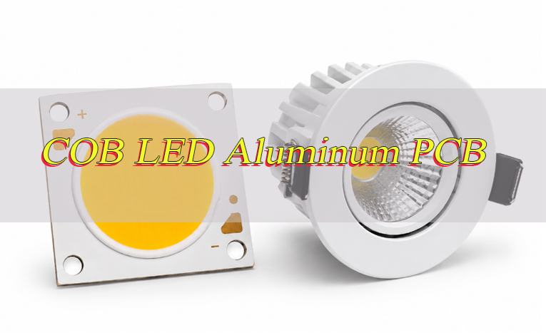
What Is a COB LED Aluminum PCB and Why Is It Used for High-Power LEDs?
A COB LED aluminum PCB is a metal-based PCB designed to carry current and move heat away from a COB LED module. It is widely used in high-power lighting because the aluminum base can spread concentrated heat more effectively than a conventional FR4 structure.
A common single-layer construction is:
Copper circuit → thermal dielectric → aluminum base
In the finished LED module, heat typically travels through:
LED junction → LED package → solder or thermal interface → copper → dielectric → aluminum base → heat sink
The copper carries current and spreads heat around the LED area. The dielectric provides electrical isolation while transferring heat into the aluminum base, which distributes it across a larger surface.
The PCB should be designed around the actual COB LED package. Confirm the pad layout, thermal-contact area, optical center, package dimensions and mounting method from the LED datasheet before finalizing the footprint.
How Does a COB LED Aluminum PCB Improve Heat Dissipation?
A COB LED aluminum PCB spreads heat from the small COB LED area into a much larger metal surface. Heat moves through the copper and dielectric before reaching the aluminum base, so these intermediate layers directly affect thermal performance.
Three parameters matter most:
- Dielectric Thermal Conductivity
Higher conductivity improves heat transfer through the insulating layer. It should be evaluated together with dielectric thickness rather than used as a stand-alone specification. - Dielectric Thickness
A thinner dielectric generally lowers thermal resistance, but it still needs enough dielectric strength and electrical isolation for the application. - Effective Heat-Transfer Area
Adequate copper and thermal-contact area helps spread heat before it crosses the dielectric. This is especially important when a high-power COB concentrates heat into a small footprint.
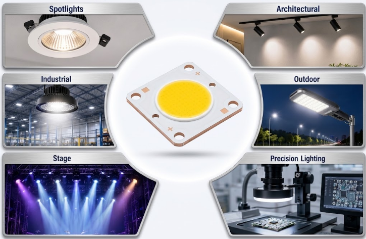
Which Applications Use COB LED Aluminum PCBs and COB Light Engines?
COB LED aluminum boards are mainly used where high light output and concentrated heat occur in the same compact assembly.
Typical applications include:
- Spotlights and Downlights: Compact products with limited space for the PCB and cooling structure.
- Track and Architectural Lighting: Modules requiring stable output and accurate LED positioning.
- High-Bay and Industrial Lighting: Higher-power products designed for long operating periods.
- Streetlights and Floodlights: Outdoor lighting exposed to high power and elevated enclosure temperatures.
- Stage Lighting: High-output sources operating at relatively high current.
- Machine-Vision Lighting: Applications where stable illumination affects imaging and inspection quality.
- Optical Inspection Equipment: Systems requiring precise LED positioning relative to optics.
- Medical Illumination: Compact lighting modules requiring stable operation and repeatable assembly.
- Projector and Imaging Light Sources: High-brightness systems with concentrated thermal loads.
- COB Light Engines: Integrated modules combining the LED, PCB, optics and cooling structure.
For a COB LED module aluminum PCB, total LED power, operating time, ambient temperature and available cooling area matter more than the number of LEDs alone.
How Should Thermal Conductivity, Dielectric Thickness and Copper Weight Be Selected?
For a COB LED aluminum PCB, these values should follow the LED power, operating current, thermal target and electrical-isolation requirement.
- Select Thermal Conductivity From Heat Density
Higher thermal conductivity is useful when the COB LED produces concentrated heat or when PCB area is limited. Moderate-power designs may not require the highest thermal class. - Keep the Dielectric Thin Without Sacrificing Isolation
A thinner dielectric lowers thermal resistance, but it still needs to meet operating-voltage, dielectric-strength and manufacturing requirements. - Match Copper Weight to Current and Geometry
Higher current may require heavier copper, but trace width and available copper area are equally important. Heavy copper does not correct an undersized current path. - Provide Enough Copper Around the Heat Source
Larger copper areas around the COB LED improve lateral heat spreading before heat passes through the dielectric. - Avoid Increasing Specifications Without Finding the Limitation
A higher W/m·K material or heavier copper provides little benefit if another part of the PCB construction limits thermal performance. - Validate the Construction During Prototyping
Test the selected copper and dielectric construction at the intended LED power before freezing the design for production.
How Should the COB LED Footprint and Thermal Pad Match the Aluminum PCB?
Use the actual COB LED package drawing rather than a generic footprint. Similar-sized COB LEDs can have different electrical pads, thermal regions and mounting structures.
Check the following before release:
- Electrical Pads: Match pad dimensions, spacing and polarity to the datasheet.
- Thermal-Contact Area: Align the PCB thermal region with the package structure.
- Optical Center: Position the emitting area correctly relative to the lens or reflector.
- Solder Mask Clearance: Keep solderable areas fully exposed.
- Package Outline: Leave enough clearance around the LED body.
- Mounting Holes: Align the PCB with the LED module and heat sink.
- Keep-Out Areas: Keep components and hardware away from optical or mounting areas.
- Heat-Sink Interface: Maintain a flat and consistent backside contact area where required.
For soldered packages, solder volume also matters. Too much solder can increase stand-off or tilt the LED, while large voids under the thermal region reduce effective heat transfer.
Stencil openings, paste volume and reflow conditions should therefore be matched to the thermal-pad geometry.
When Should You Choose an Aluminum-Core PCB Instead of a Copper-Core PCB for COB LEDs?
Use an aluminum-core PCB when the required LED temperature can be achieved with the correct dielectric and cooling structure. Move to copper only when the thermal demand exceeds what an optimized aluminum MCPCB can support.
Choose an aluminum-core PCB when:
- The Heat Density Is Within the Range of a Conventional MCPCB
Aluminum works well for many spotlights, downlights, industrial lights, streetlights and other high-power LED modules. - The Dielectric Can Meet the Thermal Target
If the correct dielectric conductivity and thickness provide enough thermal performance, a copper base adds limited value. - PCB Weight Matters
Aluminum is lighter than copper and is suitable for larger lighting assemblies. - A Standard MCPCB Structure Is Preferred
Aluminum-core PCB is widely used for both prototypes and volume LED production. - The External Cooling System Is Adequate
If heat can move effectively from the PCB into the final cooling structure, aluminum is usually sufficient.
Consider a copper-core PCB when:
- The COB LED Produces Very High Local Heat Flux
A highly concentrated thermal load may benefit from stronger lateral heat spreading. - An Optimized Aluminum PCB Still Runs Too Hot
Copper becomes more relevant after the dielectric and other major thermal limitations have already been addressed. - The Design Requires a Very Low-Resistance or Direct Thermal Path
Some specialized LED constructions use copper-based structures to shorten the path between the heat source and metal substrate. - Thermal Performance Matters More Than Weight
Copper provides higher bulk thermal conductivity but also increases PCB weight.
Use aluminum when it meets the thermal target. Move to copper only when the optimized aluminum structure is no longer sufficient.
What Steps Are Used to Manufacture and Assemble a High-Power COB LED Aluminum PCB?
A high-power COB LED aluminum PCB needs a controlled manufacturing process so the approved material, circuit and mechanical structure remain consistent through assembly.
Step 1: Review the Design and Material Requirements
Confirm the COB LED footprint, copper weight, dielectric, aluminum thickness, board dimensions, mounting holes, surface finish and required thermal interface.
Step 2: Prepare the Aluminum-Based Laminate
Use the approved copper, dielectric and aluminum construction. Material substitutions should be reviewed before production because they can change thermal and mechanical performance.
Step 3: Form and Etch the Copper Circuit
Image and etch the LED pads, power paths and supporting circuitry. Trace width and spacing must be compatible with the selected copper thickness.
Step 4: Drill and Profile the PCB
Produce mounting holes, slots and the finished outline according to the mechanical drawing. These features may align directly with the heat sink, lens holder or enclosure.
Step 5: Apply Solder Mask and Surface Finish
Keep COB LED pads and other solderable areas correctly exposed. The surface finish should match the intended assembly process.
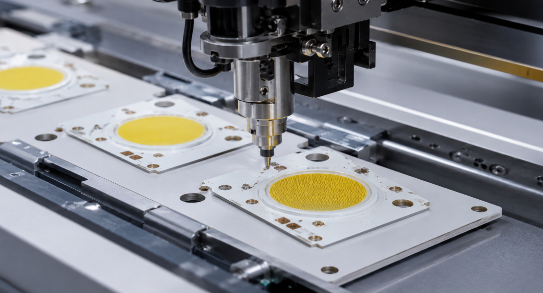
Step 6: Print Solder Paste and Place Components
Control paste volume around the LED pads and place the COB LED accurately. Positioning may affect both electrical connection and optical alignment.
Step 7: Complete Reflow and Assembly Inspection
Use an appropriate reflow profile and check solder wetting, component orientation, stand-off and visible defects after soldering.
Step 8: Mount the PCB to the Cooling Structure
Install the assembled PCB using the specified TIM, screws or clamping arrangement. Avoid uneven contact or mechanical stress on the LED package.
Step 9: Verify Electrical and Thermal Performance
Operate the assembled module at the specified load and confirm current, LED function and operating temperature before volume production.
What Steps Are Used to Inspect and Test a COB LED Aluminum PCB Before Shipment?
Inspection should cover the characteristics that can affect electrical operation, assembly fit and heat transfer.
Step 1: Verify Material and PCB Construction
Check the aluminum base, dielectric, copper thickness and finished PCB thickness against the approved specification.
Step 2: Check Dimensions and Mounting Features
Inspect the PCB outline, slots, mounting holes and critical dimensions to confirm fit with the mechanical assembly.
Step 3: Inspect Circuit and Surface Quality
Use visual inspection and AOI where applicable to identify opens, shorts, damaged pads, contamination, scratches or solder-mask registration defects.
Step 4: Perform Electrical and Insulation Testing
Verify circuit continuity and electrical isolation between the copper circuit and aluminum base.
Step 5: Check PCB Flatness
Inspect flatness when the PCB backside forms part of the thermal interface. Excessive warpage can reduce contact with the cooling surface.
Step 6: Inspect COB LED Placement and Soldering
Verify polarity, orientation, LED position, solder wetting and the condition of the main thermal-contact area.
Step 7: Perform Functional Testing
Operate the assembled module under the specified electrical conditions. Check for abnormal brightness, flicker, current behavior or other functional problems.
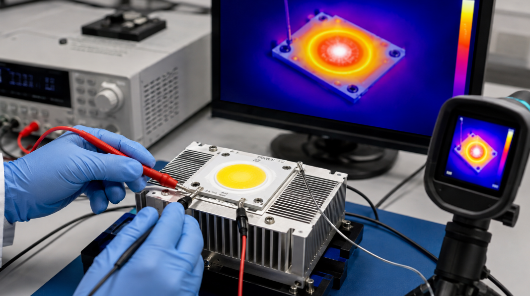
Step 8: Complete Thermal Validation
Test the module with the intended or representative cooling structure until temperature approaches a stable condition. Use thermocouples, thermal imaging or the LED manufacturer’s recommended method where appropriate.
Step 9: Confirm Production Consistency
Check that production boards use the approved materials, PCB construction and assembly requirements established during prototype validation.
What COB LED Aluminum PCB Manufacturing Capabilities Can We Provide?
Manufacturing capability determines whether the required COB LED aluminum PCB construction can be produced consistently from prototype to volume production. The table below summarizes our main MCPCB process capabilities for design and manufacturing reference.
| Item | Capabilities |
|---|---|
| Maximum Layer Count | Up to 10 layers |
| PCB Thickness | 0.3–4.0 mm |
| Maximum Board Size | Up to 610 × 1220 mm (24 × 48 in.) |
| Copper Weight | 0.5–10 oz |
| Minimum Trace / Space | 0.15 / 0.15 mm (6 / 6 mil) |
| Minimum Hole Diameter | 0.30 mm (12 mil) |
| Minimum Punch Hole Diameter | 3.0 mm (0.12 in.) |
| Minimum Hole Spacing | 0.40 mm (16 mil) |
| Maximum Aspect Ratio | 12:1 |
| Minimum Solder Pad Diameter | 0.40 mm (16 mil) |
| Thermal Conductivity | 0.8–1.5 W/m·K standard; 2.0–6.0 W/m·K high thermal conductivity |
| Warp and Twist | < 0.75% |
| Flammability | UL 94V-0 |
| Thermal Stress | 6 × 10 sec at 288°C |
| Surface Finish | ENIG, Flash Gold, Hard Gold, Selective Gold Plating, HASL, Lead-Free HASL, OSP, Immersion Silver, Immersion Tin |
Case Study: High-Power COB LED Aluminum PCB From Prototype to Production
Project Background
A high-power COB LED module required an aluminum PCB connected to an external heat sink. The board had to provide a reliable thermal path while maintaining the correct LED position, mounting-hole alignment and mechanical fit.
Project Requirements
The PCB needed to:
- Carry the required COB LED current
- Transfer heat effectively to the cooling structure
- Use an appropriate dielectric, copper weight and aluminum base
- Match the LED footprint and thermal-contact area
- Maintain PCB flatness and mounting accuracy
- Support prototype assembly and later production
Our Solution
EBest Circuit reviewed the COB LED datasheet, PCB layout and mechanical drawing before prototype fabrication.
The main actions included:
- Matching the COB LED footprint and thermal area to the package
- Reviewing dielectric thickness, copper weight and aluminum construction
- Providing sufficient copper around the main heat source
- Controlling PCB flatness and mounting-hole alignment
- Checking soldering, TIM contact and mechanical fit during prototype assembly
- Maintaining the approved construction for production
Results
Prototype validation confirmed:
- Stable COB LED mounting and alignment
- Consistent PCB-to-heat-sink contact
- A controlled thermal path
- Reliable electrical and assembly performance
- A repeatable construction for volume production
The approved PCB construction and assembly requirements were then carried forward into production.
What Specifications and Files Are Required for a COB LED Aluminum PCB Quote?
For a COB LED aluminum PCB quote, provide:
Bare PCB:
- Gerber files
- NC drill files
- Board dimensions
- Mechanical drawing
- Finished PCB thickness
- Copper weight
- Aluminum thickness
- Thermal conductivity requirement
- Dielectric thickness or material requirement
- Surface finish
- Solder mask requirement
- Quantity
- Special tolerance or testing requirements
PCB Assembly:
- BOM
- Pick-and-place file
- Assembly drawing
- COB LED part number and datasheet
- Polarity information
- Functional-test requirements
For Thermal Review:
- LED operating power and current
- Heat-sink drawing
- TIM specification
- Mounting method
- Expected ambient temperature
- Maximum allowable operating temperature
If some specifications are still open, send the available project files first for review.
Why Choose EBest Circuit for COB LED Aluminum PCB Manufacturing?
With more than 20 years of PCB manufacturing experience, EBest Circuit supports COB LED aluminum PCB projects from prototypes through mass production.
- One Supplier From Prototype to Production
PCB prototyping, Metal Core PCB manufacturing, component sourcing and PCB assembly can be coordinated through EBest Circuit, reducing supplier handoffs. - Metal Core PCB Manufacturing
Our PCB range includes Metal Core PCB / MCPCB, supporting COB LED modules and other thermal-management applications. - Capacity for Volume Production
EBest Circuit has approximately 260,000 sq. ft. (28,900 m²) of monthly PCB manufacturing capability. - Support for Urgent Projects
Expedited service is available for eligible projects, with qualifying urgent boards capable of shipment within 24 hours after requirements are confirmed. - Quality and Compliance
EBest Circuit holds ISO 9001:2015, IATF 16949, ISO 13485:2016, AS9100D, UL, RoHS and REACH credentials.
Welcome to contact us if you have any request for COB LED aluminum PCB.
FAQs About COB LED Aluminum PCBs
Q1: Does a COB LED need a constant-current driver?
A1: Usually yes. A high-power COB LED is normally driven by a constant-current driver so current remains controlled as forward voltage changes. If the module already includes current regulation, follow its datasheet.
Q2: Should multiple COB LEDs be connected in series or parallel?
A2: Series connection is generally easier to control because each COB receives the same current. Parallel branches need current balancing because forward-voltage differences can produce unequal current sharing.
Q3: How should the LED driver voltage range match a COB LED?
A3: The driver’s output-voltage range must cover the forward voltage of the COB LED or complete LED string. Add the forward voltages of series-connected COB LEDs before selecting the driver.
Q4: Can a high-power COB LED be dimmed with PWM?
A4: Yes, when the driver supports it. Use the dimming method specified by the driver manufacturer rather than switching LED power directly.
Q5: Is it better to run a COB LED below its maximum rated current?
A5: Often yes. Lower current reduces thermal load and provides more operating margin. Select the working current from the LED manufacturer’s current, temperature and light-output data.
Q6: Can a COB LED be connected or disconnected while the driver is powered?
A6: It is better to avoid it. Hot-plugging can expose the COB LED to electrical transients. Turn the driver off unless the system is specifically designed for hot swapping.
Q7: Can a reflector or lens touch the COB LED?
A7: Optical parts should not press directly against the emitting surface or electrical contacts. Use a suitable holder to maintain alignment and prevent damage.
Q8: Can a failed COB LED be replaced on the MCPCB?
A8: In many designs, yes. Replaceability depends on the attachment method and thermal mass of the MCPCB. Rework temperature and heating time need careful control.
Q9: Should a high-power COB LED system include overtemperature protection?
A9: It is useful when cooling conditions can vary. Temperature sensing can reduce LED current or shut the system down if temperature exceeds the defined limit.
Q10: What happens if one parallel COB LED branch fails open?
A10: The remaining branches may carry more current when they share one constant-current source. Parallel designs should consider current balancing or independent current regulation.
Conclusion
A reliable COB LED aluminum PCB depends on the dielectric, copper layout, LED interface and metal substrate being matched to the actual electrical and thermal load.
EBest Circuit supports metal core PCB manufacturing, prototyping, component sourcing, PCB assembly and mass production. For a high-power COB LED aluminum PCB, COB LED module or light engine project, send your files and requirements to sales@bestpcbs.com for a quotation.
You may also like
Tags: aluminum PCB for COB LED, COB aluminum PCB, COB LED Aluminum PCB, COB LED MCPCB, COB LED module aluminum PCB