

Heavy copper PCB for thermal management is used when high-current circuits must reduce resistance, control heat and maintain reliable operation. It improves heat spreading through thicker copper, wider current paths, thermal vias, copper planes and suitable materials.
For power electronics, thermal design should be confirmed before PCB fabrication. Copper thickness, trace width, spacing, stackup, materials, surface finish and testing all affect current capacity, temperature rise and product life.

Why Is Heavy Copper PCB for Thermal Management Important in High-Current Applications?
Heavy copper PCB for thermal management is important because high current creates heat inside copper conductors. If the copper area is too small, resistance rises, voltage drops and local hotspots appear around power devices, connectors and output terminals.
The main goal is lower temperature rise under continuous load. In power electronics, high temperature can damage solder joints, weaken insulation, shorten component life and cause unstable output.
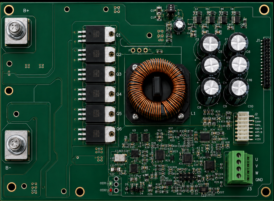
Typical high-current applications include:
- EV chargers and battery systems
- Motor drives and industrial controllers
- Power supplies and DC-DC converters
- Solar inverters and energy storage systems
- High-power LED drivers
- Welding equipment and power distribution modules
A well-designed heavy copper PCB works as both an electrical conductor and a heat spreading structure. It helps reduce external wiring, improve compactness and increase power reliability.
How Does Heavy Copper PCB for Thermal Management Improve Heat Dissipation?
Heavy copper PCB for thermal management improves heat dissipation by increasing copper cross-sectional area. Thicker copper lowers conductor resistance, reduces I²R loss and spreads heat across a wider area.
Heat usually moves from power components into pads, traces, copper pours, planes, thermal vias and then to air, heatsinks or metal housings. The key is a continuous heat path from heat source to cooling area.
Main heat-control functions include:
- Lower resistance: reduces self-heating in current paths.
- Wider heat spreading: moves heat away from MOSFETs, relays and connectors.
- Copper planes: distribute heat across larger board areas.
- Thermal vias: transfer heat between layers.
- Balanced current paths: prevent one area from carrying too much current.
Heavy copper alone is not enough. The PCB must also use proper trace width, spacing, via arrays and cooling structure.
What Copper Thickness Is Suitable for Heavy Copper PCB for Thermal Management?
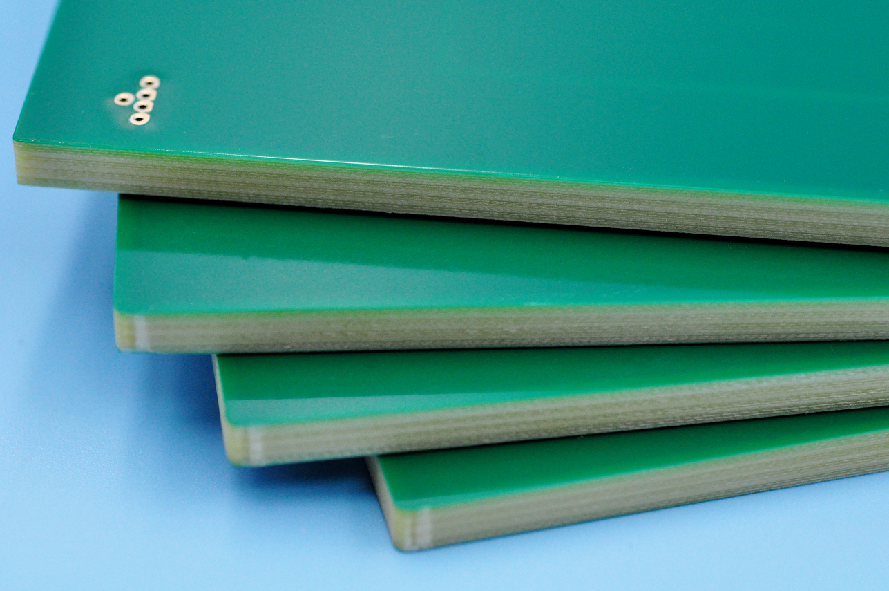
Copper thickness should be selected by current, temperature rise, trace width, board size, cooling condition and manufacturing capability. In many projects, 3 oz copper or above is considered heavy copper. For stronger power paths, 4 oz to 6 oz is common.
Higher copper weight can reduce resistance, but it also increases etching difficulty, minimum spacing, solder mask risk, lead time and cost. The best choice is not the thickest copper, but the copper weight that meets the electrical and thermal target with safe margin.
| Copper Weight | Thickness | Typical Use | Design Note |
|---|---|---|---|
| 2 oz | 70 μm | Medium power PCB | Easier to fabricate |
| 3 oz | 105 μm | Basic heavy copper PCB | Common high-current option |
| 4 oz | 140 μm | Power control PCB | Wider spacing advised |
| 6 oz | 210 μm | Motor drive, converter | Strong DFM review needed |
| 8 oz+ | 280 μm+ | Extreme current design | Higher cost and tighter process |
Selection rule: choose copper thickness based on current load, allowable temperature rise and manufacturable spacing.
How Should Trace Width Be Designed for High-Current Heavy Copper PCB?
Trace width should be designed by current load, copper thickness, temperature rise, trace length and layer position. The goal is lower resistance, lower voltage drop and stable temperature under continuous load.
Key design rules include:
- Calculate trace width by working current and peak current. Continuous current affects long-term heating, while peak current affects short-time overload safety.
- Set an allowable temperature rise before routing. Many power designs use temperature rise limits such as 10°C, 20°C or 30°C, depending on product environment and reliability target.
- Check voltage drop on long current paths. A trace may pass current, but excessive voltage drop can still cause unstable output or lower power efficiency.
- Use wider traces near heat-sensitive areas. Connectors, MOSFETs, relays, fuses and output terminals should avoid narrow neck-down routing.
- Avoid sharp corners and sudden width changes. Smooth transitions reduce current crowding and local heating.
- Use copper pours when board space allows. Large copper areas spread current better than narrow single traces.
- Use parallel layers for higher current. When one layer cannot carry the load safely, connect multiple copper layers with enough vias.
- Separate power traces from signal traces. High-current paths can generate heat and noise, which may affect control signals or sensing circuits.
Before production, buyers should provide working current, peak current, ambient temperature and allowed temperature rise for DFM review.
How Should Spacing Be Controlled to Prevent Heat and Voltage Risks?
Spacing should be controlled by copper thickness, voltage level, etching tolerance, solder mask capability and insulation requirement. The main goal is preventing shorts, leakage, arcing and solder mask failure.
Key spacing rules include:
- Increase spacing as copper thickness increases. Thick copper is harder to etch, so tight spacing can leave copper residue or cause short circuits.
- Check creepage and clearance in high-voltage areas. Power supplies, inverters, chargers and battery systems should leave enough insulation distance between different potentials.
- Keep high-current copper away from sensitive signals. This reduces heat transfer, electromagnetic noise and unstable signal behavior.
- Avoid dense routing between heavy copper traces. Dense spacing increases etching difficulty and reduces manufacturing yield.
- Reserve enough solder mask dam width. Thick copper creates higher edges, so narrow solder mask dams may break, bridge or expose copper.
- Add more clearance around connectors and terminals. These areas often carry high current and mechanical stress, so they need stronger insulation margin.
- Consider coating or insulation treatment for harsh environments. Humidity, dust, salt spray and pollution can increase leakage risk.
- Confirm spacing rules with the PCB factory before layout release. Heavy copper spacing depends on actual copper weight and process capability.
Good spacing improves electrical safety, manufacturing yield and long-term reliability under heat, voltage and humidity stress.
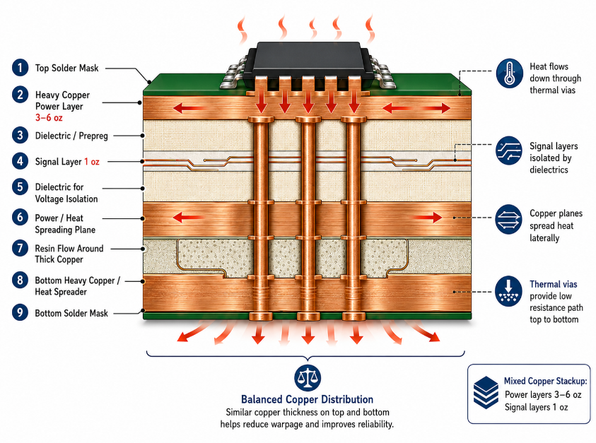
How Should Stackup Be Planned for Heavy Copper PCB for Thermal Management?
Stackup should be planned around current path, heat path, insulation and copper balance. For heavy copper PCB for thermal management, the stackup must support stable current flow, effective heat spreading and reliable lamination.
Key stackup rules include:
- Place heavy copper on power layers. Use thick copper where current actually flows, instead of applying heavy copper to every layer.
- Keep copper distribution balanced. Large heavy copper areas on only one side can cause warpage, bow and twist during lamination.
- Use continuous copper planes for heat spreading. Power planes and copper pours help distribute heat away from hot components.
- Plan dielectric thickness for voltage isolation. High-voltage circuits require enough insulation between copper layers to reduce breakdown risk.
- Separate power layers from sensitive signal layers. High-current switching loops should not be placed close to low-level control or sensing traces.
- Use thermal vias to connect heat paths. Vias should connect top copper, inner planes and bottom copper when heat must move through the PCB.
- Allow enough resin flow around thick copper. Poor resin fill can cause voids, delamination or weak insulation.
- Use mixed copper stackup for cost control. For example, power layers can use 3 oz to 6 oz copper, while signal layers use thinner copper for easier routing.
A good stackup is not only thick. It must be thermally useful, electrically safe, mechanically balanced and manufacturable in batch production.
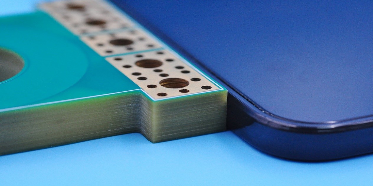
How Do Thermal Vias Improve Heat Transfer in Heavy Copper PCB?
Thermal vias improve heat transfer by moving heat from surface pads to inner or bottom copper layers. They are often placed near MOSFETs, regulators, power LEDs, connectors and copper pours.
One via has limited thermal capacity. For high-current and high-heat designs, via arrays are more effective because they reduce thermal resistance and share current when connected to the same net.
Good thermal via design includes:
- Place vias close to heat sources.
- Use via arrays instead of isolated vias.
- Connect vias to copper planes or heat spreading areas.
- Check finished hole size and plating thickness.
- Use filled or plugged vias under assembly-sensitive pads.
- Avoid solder wicking through open vias.
- Keep via distribution symmetrical around hot components.
Thermal vias must follow both thermal and electrical rules. If they carry current, via wall thickness and current sharing must be checked carefully.
What Materials Improve Heavy Copper PCB Heat Dissipation?
Materials affect heat transfer, insulation strength and board stability. For heavy copper PCB, material selection should match current load, heat path, operating temperature and product environment.
Common material options include:
| Material | Strength | Suitable Use |
|---|---|---|
| High-Tg FR-4 | Better heat resistance and dimensional stability | Power control PCB, industrial PCB |
| Aluminum Base | Transfers heat quickly to metal base | LED drivers, power modules |
| Copper Base | Higher thermal conductivity than aluminum | High-power converters, compact power boards |
| Ceramic Substrate | High temperature resistance and good insulation | Special power devices, high-reliability electronics |
| High-Thermal Laminate | Better heat flow than standard FR-4 | Compact power PCB with limited space |
Key selection rules include:
- Use High-Tg FR-4 for general heavy copper power boards. It improves thermal stability and reduces deformation during soldering or long-term operation.
- Use aluminum base when heat must move downward quickly. This is common in LED, lighting and power module designs.
- Use copper base for higher power density. Copper base costs more, but it provides stronger heat transfer for compact high-current products.
- Use ceramic for special high-temperature applications. It is suitable when the design requires strong insulation, high heat resistance and stable electrical performance.
- Check dielectric thermal conductivity. Copper spreads heat well, but poor dielectric material can block heat transfer between copper and the base layer.
- Match material with assembly temperature. Reflow soldering, selective soldering and component heat exposure should not damage laminate stability.
The best material is not always the most expensive one. It should support the real heat path and meet electrical, thermal and cost requirements.
What Surface Finish Works Best for Heavy Copper PCB for Thermal Management?
Surface finish affects solderability, pad flatness, oxidation resistance, storage life and assembly quality. For heavy copper PCB for thermal management, the finish should match component type, soldering process, RoHS requirement and cost target.
Common surface finishes include:
| Finish | Strength | Limitation |
|---|---|---|
| ENIG | Flat surface, good shelf life, fine-pitch compatible | Higher cost |
| HASL | Strong solderability and lower cost | Less flat surface |
| Lead-Free HASL | RoHS-compatible and good solderability | Higher thermal exposure |
| OSP | Flat surface and low cost | Shorter shelf life |
| Immersion Silver | Good conductivity and solderability | Sensitive to handling and storage |
Selection rules include:
- Choose ENIG for fine-pitch components or flat pad requirements. It is suitable for mixed power and signal designs where assembly accuracy matters.
- Choose HASL for larger power pads and cost-sensitive boards. It works well when pad flatness is not critical.
- Choose lead-free HASL when RoHS compliance is required. It is common for industrial and export products, but process heat must be considered.
- Choose OSP for simple assembly and short storage cycles. It is cost-effective, but handling and storage control must be strict.
- Choose immersion silver when conductivity and solderability are priorities. It requires careful packaging to avoid oxidation or contamination.
- Review solder mask coverage before production. Thick copper creates raised edges, so solder mask adhesion, dam width and exposed copper risk must be checked.
For most heavy copper power boards, ENIG and lead-free HASL are common choices. The final decision should depend on assembly difficulty, storage time and reliability requirements.
What Manufacturing Challenges Affect Heavy Copper PCB Thermal Performance?
Heavy copper PCB manufacturing is more difficult than standard PCB production. Thick copper affects etching, plating, lamination, drilling, solder mask and final inspection. Each problem can reduce thermal performance if not controlled.
Key challenges and solutions include:
- Etching undercutThick copper needs longer etching time, which can narrow the final trace width. This may increase resistance and heat rise.Solution: enlarge trace width and spacing during design, confirm etching tolerance with the factory and avoid overly dense heavy copper routing.
- Insufficient spacingTight spacing between thick copper traces can cause copper residue, short circuits or solder mask bridging.Solution: use wider spacing for high copper weight, especially around high-voltage and high-current areas. Confirm minimum spacing before layout release.
- Uneven copper platingPoor plating can weaken vias, reduce current capacity and create unreliable heat paths between layers.Solution: check finished copper thickness, via wall plating and microsection results for critical current-carrying vias.
- Resin voids around thick copperThick copper patterns require enough resin flow during lamination. Poor filling can cause voids, weak insulation or delamination.Solution: balance copper distribution, avoid extreme copper density differences and review lamination structure before production.
- Board warpageHeavy copper on only one side can create stress during lamination and soldering, causing bow or twist.Solution: keep copper distribution symmetrical, use balanced stackup and avoid large unbalanced copper areas.
- Solder mask thinningRaised copper edges make solder mask coverage more difficult. Thin solder mask may expose copper or reduce insulation reliability.Solution: increase solder mask clearance, check dam width and inspect solder mask adhesion on thick copper edges.
- Drilling and via reliability issuesHigh-current vias must have enough hole size and plating thickness. Weak vias may crack during thermal cycling.Solution: use via arrays, larger finished holes when possible and microsection inspection for critical vias.
- Higher scrap risk and longer lead timeHeavy copper boards require tighter process control, more inspection and more conservative design rules.Solution: complete DFM review before fabrication, validate prototypes before batch orders and avoid pushing minimum design limits.
A reliable heavy copper PCB should be designed with manufacturing limits in mind. Good thermal performance depends on both layout design and stable factory process control.
What Failures Happen Without Proper Heavy Copper PCB Thermal Design?
Without proper heavy copper PCB thermal design, failures often appear during load testing, thermal cycling or long-term operation. Basic continuity testing may not reveal these risks.
The root cause is usually an incomplete heat path or weak current path. A board may use thick copper but still fail if traces are narrow, vias are insufficient, spacing is unsafe or stackup is unbalanced.
Common failure modes include:
- Hotspots near MOSFETs, connectors or relays
- Burned traces caused by current concentration
- Voltage drop along long power paths
- Cracked via barrels after thermal cycling
- Delamination caused by trapped heat
- Solder joint fatigue from repeated expansion
- Insulation breakdown in high-voltage areas
- Unstable output under continuous load
Project example: A power control PCB overheated near the output connector during load testing. The design was improved by widening the copper pour, adding thermal via arrays, balancing inner copper planes and increasing solder mask clearance. After prototype validation, the hotspot was reduced and the design was ready for batch production.
FAQs About Heavy Copper PCB for Thermal Management
Q1: What copper thickness should I choose for a high-current PCB?
A1: For many high-current projects, heavy copper usually starts from 3 oz copper. Common options are 3 oz, 4 oz and 6 oz, depending on current load, trace width, temperature rise and cooling condition. Very high-current boards may use 8 oz or higher, but cost and manufacturing difficulty increase.
Q2: How much current can a heavy copper PCB carry?
A2: Current capacity depends on copper thickness, trace width, layer position, temperature rise and airflow. A 3 oz copper trace can carry more current than 1 oz copper at the same width, but there is no fixed number for all designs. The safe value should be calculated by current, allowed temperature rise and actual layout.
Q3: Is 3 oz copper enough for thermal management?
A3: 3 oz copper is enough for many medium to high-current PCB designs when trace width, copper pour and thermal vias are properly planned. If the board has continuous high current, limited airflow or compact space, 4 oz to 6 oz copper may provide better thermal margin.
Q4: When should I use 6 oz copper instead of 3 oz copper?
A4: Use 6 oz copper when the design has higher current, longer power paths, stricter temperature rise limits or limited board space. It is common in motor drives, converters, battery systems and industrial power boards. However, 6 oz copper needs larger spacing, stronger DFM review and tighter process control.
Q5: Does heavy copper PCB reduce the need for a heatsink?
A5: Heavy copper PCB can reduce hotspot temperature and improve heat spreading, but it does not always replace a heatsink. If power devices generate high heat continuously, a heatsink, metal housing or forced airflow may still be required. Heavy copper mainly improves the PCB heat path and current path.
Q6: What files should I send for a heavy copper PCB quote?
A6: Buyers should send Gerber files, drill files, stackup, copper weight, board thickness, material, surface finish, solder mask color, quantity and IPC class. For thermal review, also provide working current, peak current, ambient temperature and allowed temperature rise.
Q7: Why is spacing larger on heavy copper PCB?
A7: Thick copper is harder to etch than standard copper. If spacing is too small, copper residue, short circuits or solder mask bridging may happen. As copper weight increases from 3 oz to 6 oz, spacing usually must be enlarged to improve yield and insulation reliability.
Q8: Can heavy copper PCB be used with fine-pitch components?
A8: Yes, but the design should separate power areas from fine-pitch signal areas. Fine-pitch pads need flatness and tight tolerance, while heavy copper areas need wider spacing and stronger solder mask control. A mixed design using heavy copper for power paths and thinner copper for signal areas is often better.
Q9: What surface finish is better for heavy copper PCB?
A9: ENIG is often suitable when flatness, shelf life and fine-pitch assembly are important. Lead-free HASL is common for larger power pads and RoHS projects. OSP can reduce cost but requires shorter storage control. The choice should match component type, soldering process and reliability target.
Q10: What tests are important for heavy copper PCB reliability?
A10: Important tests include electrical testing, AOI, copper thickness measurement, solder mask inspection, microsection and thermal stress testing. For high-current vias, microsection can confirm plated hole wall quality. For critical projects, buyers should confirm inspection requirements before mass production.
Q11: What causes heavy copper PCB overheating?
A11: Overheating is usually caused by narrow traces, insufficient copper area, weak thermal vias, poor airflow, unbalanced current paths or wrong copper thickness. Even a 6 oz board can overheat if the current path has a narrow bottleneck or poor heat transfer to the cooling area.
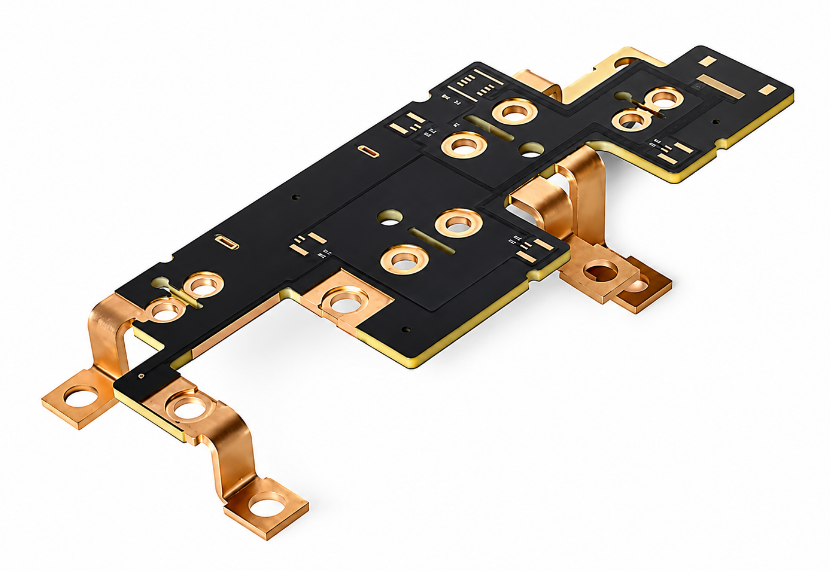
Q12: Can heavy copper PCB replace a busbar?
A12: Heavy copper PCB can replace a busbar in some compact power designs when current, temperature rise and mechanical stress are within PCB limits. For very high-current systems, a busbar or PCB-busbar hybrid structure may still be safer. The decision should be based on current level and thermal test results.
Q13: How can I reduce heavy copper PCB cost?
A13: Cost can be reduced by using heavy copper only on power layers, avoiding unnecessary layer count, keeping spacing manufacturable and choosing a practical surface finish. For example, power layers may use 3 oz to 6 oz copper while signal layers use thinner copper to control cost.
Q14: What industries commonly use heavy copper PCB for thermal management?
A14: Heavy copper PCB for thermal management is widely used in EV chargers, battery management systems, motor drives, solar inverters, power supplies, LED drivers, welding equipment and industrial controllers. These applications usually require high current capacity, lower temperature rise and long service life.
A reliable heavy copper PCB must combine suitable copper thickness, safe trace width, controlled spacing, balanced stackup, effective thermal vias, proper materials, suitable surface finish and strict inspection. The strongest design is not simply the thickest copper board, but the board with a complete and manufacturable thermal path.
For selection, engineers should confirm current load, temperature rise, voltage drop, material grade and assembly conditions before production. For procurement, buyers should choose a source factory that provides DFM review, stable process control, inspection reports and repeatable batch quality. To discuss a custom heavy copper PCB project or request a quotation, contact EBest Circuit at sales@bestpcbs.com.
You may also like


Tags: heavy copper pcb, Heavy Copper PCB for Thermal Management, Heavy Copper PCB Thermal Management