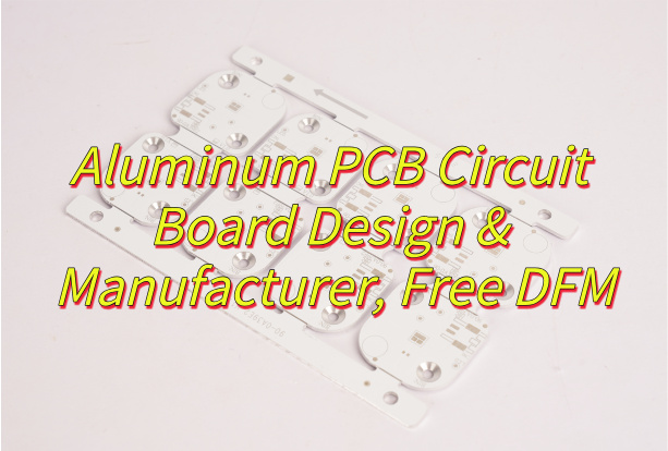
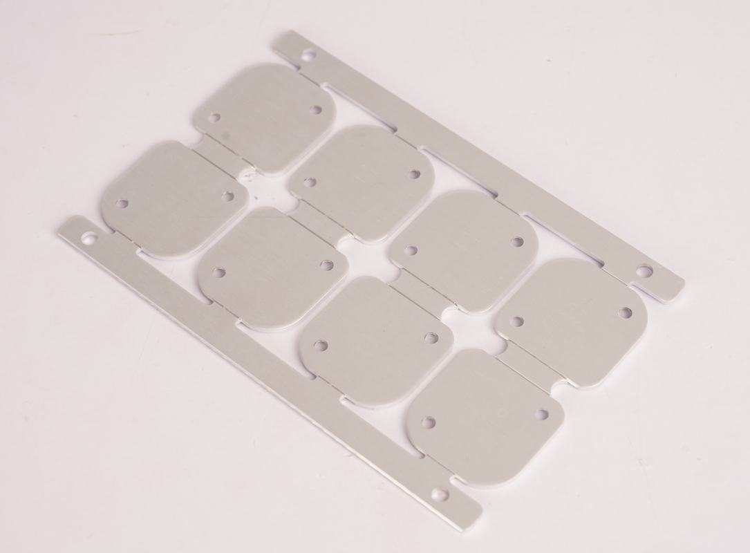
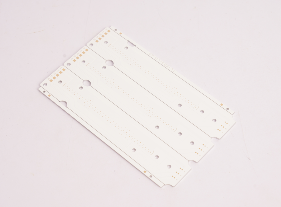
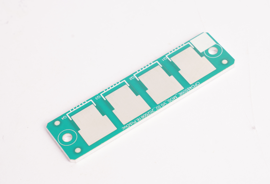
Why choose aluminum PCB circuit board for your project? These high-performance boards combine superior thermal management with structural durability, making them ideal for LED, automotive, and power electronics. This guide covers their structure, benefits, design tips, and manufacturing process to help you make informed decisions.
- Does heat dissipation design drag down product life?
- Is it difficult to get professional support for small batches?
- Does batch stability affect the pace of mass production?
EBest Circuit (Best Technology) Can Provide:
- Accurate heat dissipation solution: Patented aluminum substrate (5.2W/m·K) with thermal simulation optimization reduces temperature rise by 35%.
- Flexible cooperation model: 10 pieces minimum order, providing full technical support from design to mass production.
- Reliable Batch Quality Inspection: Provide material traceability report + reliability test data for each batch.
Welcome to contact EBest Circuit (Best Technology) if you’re interested in aluminum PCB board: sales@bestpcbs.com.
What Is An Aluminum PCB Circuit Board?
An aluminum PCB circuit board (printed circuit board) is a specialized circuit board type constructed using an aluminum alloy base material instead of conventional fiberglass substrates like FR-4. This metal-core foundation serves as a heat dissipation solution, redirecting warmth away from temperature-sensitive electronic components.
These boards are formally categorized as metal-core PCBs (MCPCBs), with aluminum being the most widely adopted base material. The essential purpose centers on thermal management, aluminum efficiently absorbs and spreads heat generated during circuit operation, preventing damage to parts like LED emitters, power transistors, or voltage regulators. This characteristic makes aluminum PCBs a practical choice in applications demanding real-world cooling performance beyond traditional boardsâ capabilities.

What Is the Structure of Aluminum PCB Board?
- Circuit Layer (Copper Foil): Composed of electrolytic copper foil, typically 1 oz to 3 oz thickness. Serves as the conductive pathway for electrical signals.
- Dielectric Layer (Thermal Insulation): A thermally conductive but electrically insulating material (e.g., epoxy resin with ceramic fillers). Transfers heat from the circuit layer to the metal substrate while preventing electrical shorts.
- Metal Substrate (Aluminum Base): A thick aluminum plate (usually 1mm to 3mm thickness). Provides mechanical rigidity, heat dissipation, and acts as a heat sink for high-power components.
- Adhesive Layer (Bonding Film): A thin adhesive film between the dielectric layer and aluminum substrate. Ensures strong adhesion and thermal conductivity between layers.
Aluminum PCB Circuit Board Specification
| Parameter | Specification Range |
| Base Material | 5052/6061 Aluminum Alloy |
| Copper Thickness | 1oz – 4oz (35ÎŒm – 140ÎŒm) |
| Dielectric Layer | 50ÎŒm – 150ÎŒm |
| Max Operating Temp | 130°C – 150°C |
| Thermal Resistance | 0.5°C/W – 3.0°C/W |
| Breakdown Voltage | 2kV – 5kV |
| Surface Finish | HASL, ENIG, OSP |
| Min Trace Width | 0.1mm – 0.3mm |
| Min Hole Size | 0.3mm – 0.5mm |
| Panel Size | 500mm x 600mm (max) |
What Are the Pros and Cons of Aluminum PCB Circuit Board?
Advantages of aluminum PCB circuit board:
- Superior Thermal Management: Conducts heat 8-10x faster than standard FR4, preventing overheating in high-power LEDs, motor drives, and power converters.
- Enhanced Durability: Resists vibration and mechanical stress better than fiberglass PCBs, ideal for automotive and aerospace applications.
- Longer Component Lifespan: Stable thermal performance minimizes thermal expansion stress, reducing failure rates in power electronics.
- Cost-Effective for High-Power Designs: Lower lifetime costs compared to FR4 + external cooling solutions in applications like LED lighting and industrial power supplies.
- Eco-Friendly Material: 100% recyclable, aligning with green manufacturing and RoHS compliance.
Disadvantages of aluminum PCB circuit board:
- Higher Upfront Cost: 20-30% more expensive than FR4 due to specialized dielectric layers and metal-core processing.
- Limited Complexity: Mostly 1-2 layers; multilayer designs are rare and costly (e.g., hybrid constructions with FR4 sections).
- Challenging Rework: Difficult to modify after productionâdrilling or cutting risks damaging the aluminum substrate.
- Electrical Isolation Risks: Dielectric layer defects (e.g., voids) may cause shorts in high-voltage applications (>1kV).
- Poor High-Frequency Performance: Higher parasitic capacitance distorts signals above 500MHz, making RF/microwave circuits impractical.

What Are Aluminum PCB Board Used for?
- High-Power LED Lighting – Commercial lighting, automotive headlamps, backlight units.
- Power Electronics – Switch-mode power supplies, motor controllers, solar inverters.
- Automotive Systems – Electric vehicle battery modules, engine control units, LED taillights.
- Audio Amplifiers – High-fidelity amplifiers, professional audio equipment, RF power modules.
- Renewable Energy – Solar panel junction boxes, wind turbine converters, energy storage systems.
- Medical Devices – Surgical lighting, diagnostic imaging equipment, laser therapy systems.
- Industrial Controls – Programmable logic controllers (PLCs), sensor modules, robotics.

How to Design Aluminum LED PCB for Better Heat Dissipation?
Methods about how to design aluminum LED PCB for better heat dissipation:
- Choose High-Thermal-Conductivity Dielectric Layersâ: Use ââ„2.0 W/mKâ dielectric materials (e.g., Bergquist HT-07000) to bridge heat from LEDs to the aluminum base.
- Maximize Copper Thickness for Power Tracesâ: Prioritize â2â4 oz copperâ to reduce resistive heating and improve thermal spreading.
- Implement Thermal Vias Under LED Padsâ: Place âarrays of vias (0.3â0.5mm diameter)â beneath LED footprints to direct heat to the aluminum core.
- Avoid Thermal Islands in Layoutsâ: Connect all high-power components to large copper pours, ensuring heat paths are âcontinuous and low-impedanceâ.
- Balance Copper Distributionâ: Symmetrical copper layers prevent warping and reduce âlocalized hotspotsâ during thermal cycling.
- Optimize LED Spacingâ: Maintain ââ„5mm spacingâ between high-power LEDs to minimize cross-heating effects.
- Use Thermal Simulation Earlyâ: Tools like âANSYS Icepakâ or âMentor FloTHERMâ can predict hotspots before prototyping.
How Are Aluminum PCBs Made?
Aluminum PCB Manufacturing Process:
1. Material Cutting: Cut aluminum alloy substrate (e.g., 1050, 6061) to specified dimensions.
2. Surface Cleaning: Clean aluminum and copper foil surfaces to remove oils, oxides, or contaminants.
3. Dielectric Layer Coating: Apply thermally conductive epoxy or prepreg to the aluminum substrate.
4. Copper Foil Lamination: Bond electrolytic copper foil (1â3 oz) to the dielectric layer under heat and pressure.
5. Circuit Etching: Print photoresist, expose to UV light, and etch excess copper with alkaline/acidic solutions.
6. Drilling: Machine-drill via holes using carbide bits, ensuring positional accuracy (±0.05mm).
7. Through-Hole Plating: Electroplate drilled holes to create conductive vias (copper thickness â„1.5 mils).
8. Surface Finish Application: Apply HASL, ENIG, or OSP to protect copper and enhance solderability.
9. Thermal Stress Testing: Subject boards to thermal cycling (-40°C to +125°C) to validate durability.
10. Final Inspection & Packing: Conduct 100% visual and dimensional checks before packaging.

Why Choose EBest Circuit (Best Technology) as Aluminum PCB Manufacturer?
Reasons why choose EBest Circuit (Best Technology) as aluminum PCB manufacturer:
- Certified Compliance (ISO 9001, UL, RoHS, ISO 9001, IATF 16949 ): Mitigates regulatory risks and ensures products meet global standards for safety and environmental compliance.
- Free DFM (Design for Manufacturability) Analysis: Optimizes PCB layouts to reduce material waste, lower production costs, and avoid late-stage design revisions.
- Turnkey Solutions â Full-service PCB manufacturing from design to delivery, accelerating your productâs time-to-market.
- Fast Turnaround â 24-hour rapid prototyping and industry-leading production lead times.
- Stable Supply Chain â Guaranteed material availability with minimal risk of delays.
- Responsive Support â Dedicated customer service with a 2-hour response guarantee for urgent requests.
- Competitive & Transparent Pricing â No hidden costs, offering the best value without compromising quality.
- Stringent Quality Control with 100% Inspection: Eliminates hidden defects, reduces rework costs, and ensures reliability in high-current/thermal applications.
If you have any request for aluminum PCB, welcome to contact us: sales@bestpcbs.com.


