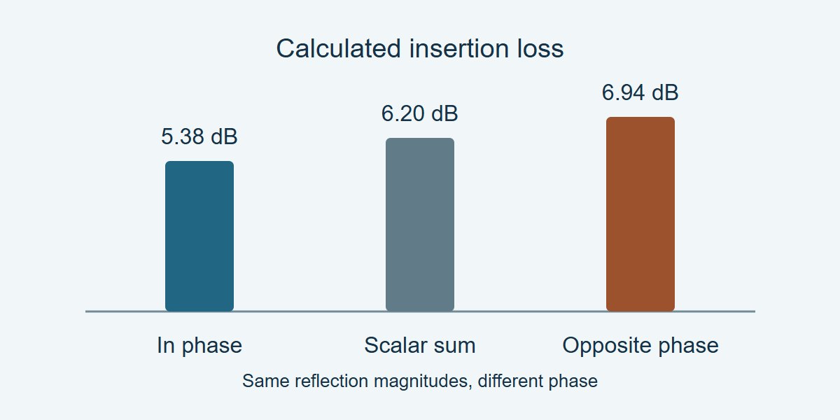
Do not add the insertion loss of two PCB blocks in dB unless the reflections at their joint are small enough for your error budget. Join the full complex two-port models first. In the example below, the same two forward-transmission magnitudes predict 6.20 dB of loss if you add them, but the complete model gives 5.38 dB or 6.94 dB depending on the reflection phase. None of those figures is measured board data.
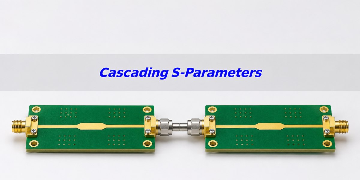
Cascading S-Parameters: What Are You Connecting?
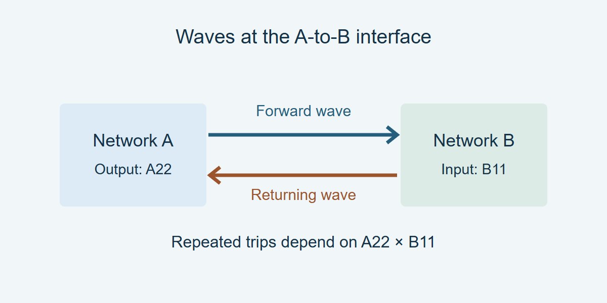
A cascade puts the output of network A into the input of network B. The wave transmitted by A travels toward B, and a wave reflected from B travels back toward A. If both internal ports reflect, some of that wave makes repeated trips across the interface. The combined transmission depends on both the loss through each network and the complex size and phase of those returning waves.
Draw the port order, joint and exterior reference planes before opening either S2P file. If A and B were measured with the same removable coax launch attached, their separate measurements might include duplicate hardware. Do not join those files as though the shared launch were a zero-length joint. Decide whether the physical connector or transition belongs inside A, inside B, or in a separate measured block.
S-Parameter Cascade Formula: Include the Interface Reflections
For two directly joined two-ports at the same frequency, with connected waves on compatible real reference impedances and consistent normalization, the total forward transmission is:
S21,total = A21B21 ÷ (1 − A22B11).
With no incident wave at the output of B, the wave coming back into A equals the wave entering B multiplied by B11. At A’s output, the forward wave is the direct contribution from A21 plus that returning wave multiplied by A22. Substituting one relation into the other gives the denominator. If one internal port is perfectly matched, the product A22B11 is zero and the simple S21 multiplication is exact under these assumptions.
Insertion Loss Calculation: How Much Can Adding dB Miss?
In a hypothetical calculation at one frequency, let both forward-transmission magnitudes be 0.70, and let the two internal reflection magnitudes be 0.30, or about 10.46 dB return loss each. The product estimate is 0.49, giving S21 = −6.20 dB in magnitude notation (positive insertion loss of 6.20 dB).
Now include phase. If A22B11 = +0.09, the magnitude is 0.49 ÷ 0.91 = 0.5385, giving 5.38 dB insertion loss. If the reflection product is −0.09, its magnitude is unchanged, but the result is 0.49 ÷ 1.09 = 0.4495, giving 6.94 dB insertion loss. The shortcut missed by about 0.82 dB in the first case and 0.75 dB in the second, using unrounded results. That is material in a 0.50 dB modeling budget but may be acceptable for a rough estimate with a looser budget.
If the phase is not known and the reflection-product magnitude is r < 1, the denominator magnitude lies between 1 − r and 1 + r. Bound the shortcut error across the whole band before using it. If that bound consumes your allowed margin, use the complex cascade and verify it.
S-Parameters to ABCD Conversion vs. Direct Network Connection
Do not multiply the raw S matrices as though they were transfer matrices. The variables sit on different sides of the network. Chain matrices such as ABCD can be multiplied in physical order when the input, output and current conventions match. Or use a library’s direct network connection with explicit ports, which avoids manually choosing a matrix convention.
| Approach | Use when | Check before trusting it |
|---|---|---|
| Add loss in dB | Getting a first estimate for well-matched stages | Bound reflection error against the modeling budget. No return-loss prediction. |
| ABCD or chain matrices | Cascading compatible two-ports in a documented convention | Confirm order and conversion, especially near very small S21, where common conversion formulas can be poorly conditioned. |
| Direct complex connection | Using a library with known port and impedance handling | Verify the connection map, normalization and frequency alignment. Compare with an independent assembly measurement. |
Touchstone File: Align Frequency, Port Order and Reference Impedance
Confirm the file’s frequency unit, port mapping, complex representation and reference impedance. Decide what reference planes the measured blocks include. A 50 Ω file and a 75 Ω file do not establish the geometry of a real transition; normalize or connect the full networks with a method that handles their reference impedances. Include a physical transition separately if it is part of the assembly you intend to predict.
Use the shared measured band and a documented frequency grid. Avoid extending a file outside its valid band to make the points line up. If a solver needs new points, apply the S-parameter interpolation checks before joining the models. Near a notch, a sweep that misses the feature cannot be repaired by adding more display points.
How to Verify a Cascaded S-Parameter Model on the Bench
Measure the physically joined chain with the same exterior planes, port directions and frequency band as the model. Plot the complex residuals for forward and reverse transmission and the relevant reflections. A close S21 magnitude at one frequency can hide a wrong phase slope, a flipped block or a fixture error. Save the independent assembly file with the model.
| Item | Example residual | Interpretation and next step |
|---|---|---|
| Insertion loss | Model 5.38 dB; assembly 5.56 dB; difference 0.18 dB | Within the 0.25 dB example limit if the agreed uncertainty rule is satisfied. |
| Transmission phase | Model −70°; assembly −61°; difference +9° | Outside the 5° example limit. Check the reference planes, connector delays and file orientation. |
| Reflection or reverse path | Compare relevant S11, S22 and S12 across the critical band | Not proven by the first two rows. Use the actual limits and retain the measured file. |
Where to Use a Two-Port Cascade in PCB Engineering
Cable plus RF board: Use the cable and board files to estimate loss and phase at the system interfaces. Include any adapter once. Verify total response at the intended cable position across the operating band; a changed cable route can invalidate the comparison.
Connector launch plus PCB trace: Place the join at defined geometry, not at a vague connector boundary. Check the return loss and phase as well as insertion loss. If adjacent structures couple directly across the supposed boundary, measure or simulate the combination instead of assuming independent two-ports.
Filter plus another RF stage: Check passband ripple and stopband rejection as separate tasks. A good two-port fit in the passband does not prove a deep stopband result near the instrument’s noise floor. Verify any notch that determines whether the design passes.
How to Release a Cascaded Network for Simulation
Record the original files, the model generator and version, frequency range, grid, port directions, reference impedances, joins and operations. Sanity-check with a known low-reflection case. If the assembled measurement differs, first check planes, order and repeated hardware, then compare at original sample points before blaming interpolation. For passive blocks check the resulting model as appropriate; for transient use review the required causality and bandwidth assumptions separately. If the cascade will drive a step or eye simulation, use the S-parameter DC extrapolation guide to check that the combined path has the correct low-frequency limit.
Cascading S-Parameters FAQs
Can I multiply the S21 magnitudes?
Only as an approximation unless the internal reflection product is zero. Bound the error before making a decision.
Can two lossy stages have less loss than a scalar estimate suggests?
Yes. Interface reflection phase can increase or decrease transmission relative to the scalar product. That does not imply a passive assembly creates gain.
Can I multiply the two raw S matrices?
No. Use an appropriate connection calculation or a compatible chain representation.
What if the port references are different?
Use a method that handles the reference impedances and wave conventions for both full matrices. Do not treat that as a model of unspecified physical hardware.
Can I cascade files with different frequency grids?
Only after aligning them with a justified method in their common band. Check independent points where sharp features matter.
Does agreement in dB prove the model is correct?
No. Compare the relevant complex transmission and reflection terms at matching planes.
What if there is a deep null near the conversion?
Common chain conversions can amplify numerical and measurement errors when forward transmission is tiny. Check the method’s conditioning and the measured floor.
When is a two-port model insufficient?
Use a wider model when coupling, common-mode paths, or additional ports matter and cannot be represented independently with the intended terminations.
Technical References
- Keysight ADS RF System Budget Analysis — cascade of two two-port components.
- Keysight ENA Equation Editor — network parameter representations.
- scikit-rf: Connecting Networks — explicit ports and impedance handling.
- IBIS Open Forum: Touchstone File Format Specification v2.1 — file representations and reference definitions.
Custom High-Speed PCBs With Stackup and Coupon Review
Need a custom RF or high-speed PCB? Ask EBest Circuit to review the proposed stackup and test coupon before fabrication. Send the layout or Gerbers, impedance targets, test interfaces, quantity and delivery needs to sales@bestpcbs.com for a project review and quotation.
You may also like

Tags: S Parameters, S-parameter renormalization, Touchstone file, VNA S21 Measurement