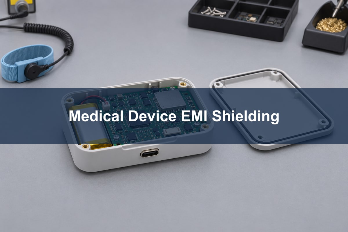
When EMI shielding fails in a compact medical device, first determine whether the disturbance bypasses the shield through a cable, leaks through a seam or enters the sensitive circuit by another path. A larger metal cover will not fix every mechanism. Compare one controlled change at a time and verify both the electromagnetic result and the device function.
Consider a hypothetical handheld monitor that behaves normally on its bench supply but occasionally produces a sensor error during immunity evaluation with its intended cable attached. The goal is to localize the coupling path, decide what to change and confirm the fix on the assembled device. This example is not a compliance procedure or a record of a tested product.
Board level shielding
Use a board shield to enclose a defined source or protect a defined victim. The can, its connection to the board reference and the return path underneath form one enclosure. A shield that covers a regulator while leaving the connector return outside the boundary may reduce a local field without changing the disturbance that reaches the sensor.
Mark three features on the layout: the suspected source, the sensitive circuit and each conductor crossing the shield boundary. Include flex tails and test leads. If the error occurs only with the external cable attached, investigate that path before changing the can. If a local source couples directly into the analog input, inspect where those circuits share geometry or return impedance.
PCB shield can
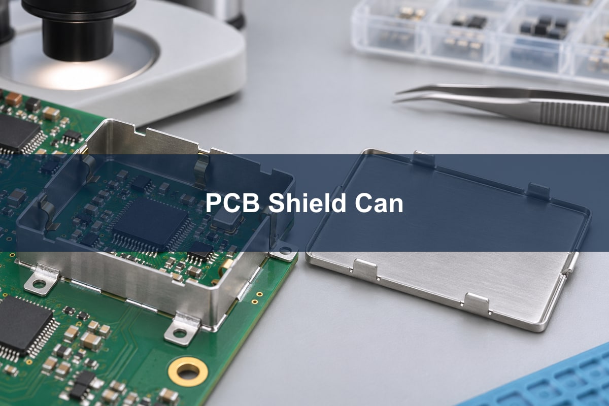
Choose a one-piece can or a removable lid according to the required RF continuity, assembly process and service access. A two-piece part can simplify inspection and rework, but the lid-to-frame interface becomes a separate contact to verify. A one-piece part still depends on how it is attached and on what passes underneath it.
| Option | Use when | Verify on the build |
| One-piece board shield | The region does not need routine access. | Attachment, coplanarity and inspection of required joints. |
| Frame with removable lid | Parts must remain accessible during build or service. | Lid seating and repeatability after approved reassembly. |
| Conductive enclosure and gasket | The coupling path crosses a case seam or port. | Mating surfaces, contact continuity and the approved boundary design. |
Use the chosen part’s drawing for footprint, flatness and height. After assembly, check that the lid does not contact tall components and that it seats with the actual board thickness and enclosure tolerances. Do not rely on a supplier shielding figure for the behavior of an assembled medical device.
EMI gasket
A conductive gasket is useful only when it provides a repeatable contact across the seam it is intended to close. Inspect the actual mating surfaces for paint, gaps, pressure variation and housing distortion. A gasket that touches at the screws but loses contact between them can leave an RF leakage path even if a continuity meter beeps.
On the monitor, compare the baseline with a reversible engineering change applied to one suspected seam. Keep cable position and operating mode unchanged. Use only changes approved for the test unit: a diagnostic bond must not bypass patient isolation, protective barriers or other safety features. If the improvement depends on hand pressure, treat that as a clue about contact repeatability rather than a production fix.
Common mode current
Look for cable common-mode current when a change in cable orientation, accessory or connector bond shifts the response more than a change to the can. A clamp around all conductors in a cable can help compare net current under repeatable conditions. The measurement is a diagnostic proxy; it does not by itself establish how much of the disturbance reaches a sensitive node.
Compare only configurations allowed by the test plan. For the example monitor, log whether the cable is attached, its routing and termination, and the operating mode. If the error follows a cable change, examine the port protection and return path. Do not copy a chassis-bonding recommendation from another product where it could change leakage current or isolation.
Near field probes
Use a probe to compare local RF activity at the shield edge, connector and nearby circuits. Keep probe orientation, distance and analyzer settings fixed. When the lid is installed, the geometry changes; use the same accessible comparison points and do not compare readings taken at different distances as if they were equivalent.
A quieter regulator region with no change at the cable entry suggests that the local shield changed one path but not necessarily the one responsible for the error. Check the cable-current trend and the device log under the same conditions. The near-field probe troubleshooting guide explains the bench comparison in more detail.
Shielding effectiveness measurement
State what was compared before reporting a shielding change in decibels. A material coupon, local probe and full assembly test measure different quantities. A local result can guide a design change but cannot be transferred directly to the installed device or to a different frequency band.
| Observation | Likely next check | What it does not prove |
| Local peak drops after lid installation. | Check cable behavior and device response. | That the final product meets emissions or immunity criteria. |
| Error changes with documented cable movement. | Investigate the connector and common-mode path. | That the shield lid is defective. |
| Result changes when the seam is pressed. | Check lid seating, gasket pressure and repeatability. | That an operator-dependent improvement is suitable for production. |
For example, a receiver reading that changes from 55 to 47 dBµV in an unchanged bench setup shows an 8 dB drop for that observation. These are hypothetical readings. Do not call the difference enclosure shielding effectiveness unless the measurement method and geometry support that claim.
EMC immunity testing
Judge immunity by how the device performs under the specified disturbance, not by how quiet its spectrum looks. Log the observable product function, disturbance and configuration together. A lower local RF reading does not prove that a sensor reading, alarm or recovery behavior stays within its approved criterion.
For the hypothetical monitor, engineering should identify the sensor error or degradation that matters, how it is logged and how normal operation is assessed after exposure. The qualified product team defines the acceptance criteria from the intended use and applicable requirements. The FDA’s EMC guidance discusses device functions, intended environments, accessories and test evidence; it does not provide a universal shield design.
EMC test plan
Freeze the released assembly and record exactly what is being verified. Include the board revision, shield and gasket parts, housing, harness, supported accessories, operating modes and approved criteria. Before the formal evaluation, repeat the baseline and the proposed change in representative configurations so a result can be traced to the actual design difference.
In the example, release the fix only after the error is absent under the agreed conditions, the change is repeatable across the planned units and assemblies, and applicable safety and performance checks remain satisfied. If the result depends on one prototype, one cable position or one lid, keep the investigation open. Formal evaluation belongs with the product team and qualified lab.
FAQ
Why can a board pass emissions but fail immunity?
Emissions and immunity ask different questions: what the device produces and how it behaves when disturbed. A shield or filter may improve one path without protecting every affected function.
Does DC continuity prove good shielding?
No. It can reveal an open bond, but it does not characterize RF impedance around the whole seam or connector. Check contact geometry and compare performance under repeatable conditions.
Can removing a shield reduce one measured peak?
Yes. Changing the cover can change coupling, resonance or current paths. Compare the complete band and required operating configurations before accepting the result.
Why does a replacement lid need its own review?
Contact geometry, coatings and fit may change even if the outer dimensions match. Compare the drawing and the assembled contact condition, then repeat the affected verification.
Should the device always be tested while charging?
Include charging or other connected modes when they are part of intended use and the applicable plan. Keep the charger and cable identification with the configuration record.
Can a clip-on ferrite prove the cable is the only problem?
No. An improvement indicates that modifying the cable path affected the outcome. Other paths can still be present. Retest the affected modes and confirm the production solution separately.
Does a shield require rechecking thermal behavior?
Consider it if the change affects ventilation, heat transfer or component clearance. Compare temperatures in the assembled unit under the specified operating conditions rather than assuming a metal cover always improves cooling.
What belongs in the supplier package?
Include the shield land pattern, part and revision, height envelope, assembly constraints and inspection points. Keep product-level immunity acceptance with the device verification plan.
References
- FDA: Electromagnetic Compatibility of Medical Devices
- Laird: Two-piece board-level shield examples
- LearnEMC: Practical electromagnetic shielding
Discuss shield and board integration
For a Best Technology fabrication or assembly review, send the PCB revision, shield drawing and inspection requirements to sales@bestpcbs.com. Keep the complete-device EMC verification plan with the product team.
You may also like

Tags: board level emi shielding, EMC, emc test, pcb design