The USB ID pin helps a legacy USB On-The-Go (OTG) device determine whether it should initially act as a host or a peripheral. Grounding the pin and leaving it floating signal different cable connections. This small difference explains why one adapter lets a compatible device control a USB accessory while an ordinary cable connects that same device to a computer.
For products using Mini-USB or Micro-USB, the connector contact, PCB connection and controller input must work together. EBest Circuit supports PCB fabrication, component sourcing and assembly for customer-designed USB interface boards, including connector inspection and agreed functional testing. Discuss your board’s manufacturing needs with sales@bestpcbs.com.
What Does the USB ID Pin Do?
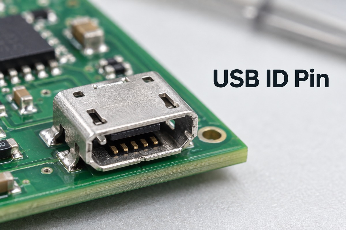
The USB ID pin function is to identify the cable end connected to a legacy OTG port. It gives a dual-role controller information about its initial role before normal USB communication begins.
A USB host initiates transfers and manages connected peripherals. A peripheral responds to the host. A portable instrument, for example, might operate as a peripheral when connected to a PC but act as a host when reading a USB flash drive, provided its hardware and software support both functions.
The ID signal helps distinguish those connections. It does not carry the measurement data, files or USB commands exchanged between the devices; those travel over the data connection.
In this context, OTG support belongs to the complete device, not simply to its five-contact connector. Adding an ID connection cannot turn a device-only controller into a USB host.
Where Is the Micro USB ID Pin in the 5-Pin Connector?
In the standard five-contact USB 2.0 Micro-USB pin assignment, ID is pin 4 and GND is pin 5. The same signal numbering applies to the five-contact Mini-USB interface.
| Pin number | Signal |
|---|---|
| 1 | VBUS |
| 2 | D− |
| 3 | D+ |
| 4 | ID |
| 5 | GND |
Descriptions sometimes call ID the “fifth pin” because it is the additional contact beyond the four signals used by a USB 2.0 Type-A connection. That does not mean its assigned pin number is 5.
The physical view also matters. A connector’s mating face and its PCB footprint are viewed from different directions, so a left-to-right sketch can be misleading without a stated viewing direction. Use the selected connector’s numbered drawing to locate pad 4 rather than assuming it is always the second pad from one particular side.
The metal shell and mounting tabs are separate from these five signal contacts. They should not be counted as extra positions in the USB pinout.
What Happens When the USB ID Pin Is Grounded or Floating?
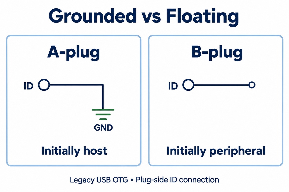
A grounded ID identifies the A end of a legacy OTG connection; a floating ID identifies the B end. The A-device starts as the host, while the B-device starts as the peripheral.
| Cable end at the OTG port | ID connection in the plug | Initial role |
|---|---|---|
| Mini-A or Micro-A | Connected to GND | A-device, initially host |
| Mini-B or Micro-B | Left unconnected | B-device, initially peripheral |
Grounded means there is an electrical path from ID to ground. The detector reads a low state.
Floating means the plug leaves ID unconnected. It does not necessarily mean the powered controller sees an unstable or zero-voltage signal. Its detection circuit may pull the input high internally.
This is why an OTG adapter and a normal peripheral cable can produce different behavior even when both provide power and data contacts. Their ID termination tells the compatible port how to begin the connection.
The word initial is important. Legacy OTG devices that support Host Negotiation Protocol can exchange host and peripheral roles later. The A/B cable identity does not change with that exchange, and the A-device remains responsible for supplying VBUS. Data role and power source are therefore not interchangeable terms.
How Is the USB ID Pin Connection Made on a PCB?
For a legacy dual-role port using ID detection, the connector’s ID contact connects to the USB controller or PHY input responsible for sensing it. The plug supplies the grounded or open condition; the board carries that condition to the detector.
The signal path is short:
- The inserted plug grounds ID or leaves it open.
- The receptacle’s ID contact carries that state onto the PCB.
- The controller or PHY detects the state and makes it available to the USB software.
A PHY is the physical-layer transceiver between the USB electrical connection and the controller. Some devices integrate both functions, so there may be no separate PHY IC on the board.
The pull-up arrangement depends on that silicon. An integrated detector may already provide the bias needed to distinguish an open plug contact from a grounded one. An external pull-up should therefore follow the controller’s reference circuit, not a generic USB wiring diagram.
For a fixed peripheral-only product, the controller documentation may permit ID to remain unused. A dual-role design normally needs to preserve the detection path. Permanently grounding the board’s ID net removes its ability to distinguish a floating plug through that signal.
ID is not part of the D+/D− differential pair and is not a power input. Connecting it to VBUS is not a substitute for implementing role detection.
What Determines the USB ID Pin Voltage?
The USB ID pin voltage depends on the detector’s bias circuit and whether the plug grounds the contact. There is no single high-state voltage that should be imposed on every USB controller.
The USB3300 PHY provides a useful example. Its internal pull-up biases an open ID input toward its 3.3 V supply, while an A-plug grounds the signal.
| USB3300 example | Expected ID condition |
|---|---|
| A-plug connected | Near 0 V |
| B-plug connected, ID pull-up active | Near 3.3 V |
These values describe that device’s circuit, not a universal instruction to add a 3.3 V connection. Another implementation can use different thresholds, biasing or detection behavior.
A high reading with the plug’s ID contact open can therefore be normal. “Floating at the plug” and “pulled high inside the controller” can both be true at the same time.
Conversely, a low voltage alone does not prove that host operation is working. It establishes the electrical state at the measured point. VBUS control, controller configuration and USB communication still have separate roles in the connection.
Does USB-C Have an ID Pin?
USB-C connectors do not have the legacy Mini/Micro-USB ID contact. They use Configuration Channel signals, CC1 and CC2, for attachment and orientation detection and the initial source/sink relationship.
| Interface | Connection-detection signals |
|---|---|
| Legacy Mini/Micro-USB OTG | ID contact grounded or left open |
| USB-C | CC1 and CC2 with the appropriate CC circuitry |
However, a USB-C controller IC can still have a pin named ID. This is a board-level logic signal, not an extra contact on the USB-C receptacle.
For example, the TUSB320 detects attachment through CC and can provide an active-low, open-drain ID output to an OTG controller. Here, the chip translates the Type-C connection state into a signal that the existing controller can use.
This distinction matters when reading a schematic: a net labeled USB_ID beside a Type-C controller does not mean the connector itself contains a legacy ID pin. It also does not mean a Micro-USB ID wire can simply be moved to CC1 or CC2. Type-C requires its own attachment and role-detection circuitry.
Why Does OTG Fail Even When the ID Pin Is Grounded?
Grounding ID supplies a role-detection signal. Successful host operation also requires compatible hardware, a working power path and software that supports the connected peripheral.
A detected host role is only the beginning. The controller must support host operation, and the USB software must enable it. A device-only controller cannot acquire that capability through an adapter.
The peripheral also needs usable VBUS power. If the host-side power switch is not enabled, or the supply cannot support the load, a flash drive or other bus-powered accessory may never start correctly.
Power does not prove a working data connection. An accessory can light up while D+/D− are disconnected, incorrectly routed through the assembly or interrupted by a damaged connector. USB enumeration, the process through which the host identifies the peripheral, will still fail.
Enumeration does not guarantee application support. A device may recognize an attached accessory but lack the driver or application function needed to use it.
For example, a portable instrument might read a flash drive successfully yet be unable to use a USB audio interface. Both connections can have a valid grounded ID state; the supported USB device classes and software behavior differ.
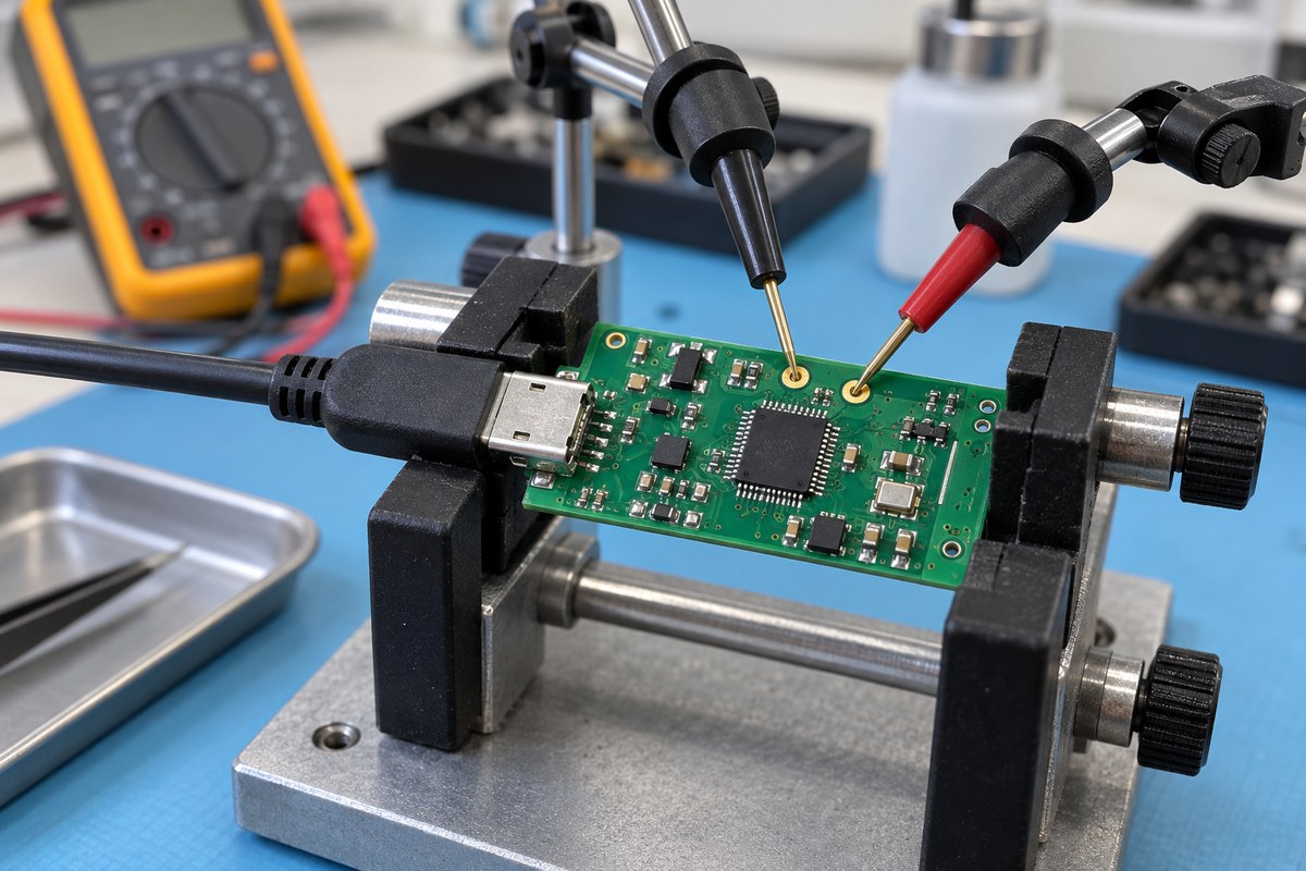
This is also why a continuity test of the ID net cannot replace a functional USB test on an assembled board.
FAQs About USB ID Pin
1. Is the USB ID pin the same as a USB Vendor ID or Product ID?
No. The ID pin is a physical electrical signal used in legacy OTG detection. Vendor ID and Product ID are identification values reported through USB device descriptors during communication.
2. Does the ID pin carry USB data?
No. On the five-contact USB 2.0 Mini/Micro interface, D+ and D− carry USB data. ID indicates the cable-end condition used for OTG role detection.
3. Why can a Micro-USB cable have five contacts but only four wires?
The ID termination can be handled locally inside the plug rather than carried as a fifth conductor along the cable. The four conductors serve VBUS, D−, D+ and GND. Contact count and cable conductor count describe different parts of the connection.
4. Can a peripheral charge with its ID contact left open?
Yes. A B-plug normally leaves ID open. Whether charging occurs, and at what current, depends on the power source and the product’s charging implementation rather than on grounding ID.
5. Does a five-pin Micro-USB connector guarantee OTG support?
No. The connector provides contacts, but the controller, power circuitry and software determine which roles the product supports. A device-only Micro-USB product can use the same five-contact signal assignment without offering host operation.
When moving a USB interface board into production, the USB ID pin connection is one part of the assembled interface. EBest Circuit can manufacture and assemble your released board and perform agreed USB functional tests using the specified firmware and accessories. Contact sales@bestpcbs.com to discuss prototype or production PCBA support.