





An MCB symbol looks simple, but reading it correctly requires more than recognizing a breaker-shaped graphic. A drawing may use IEC conventions, ANSI/IEEE-style symbols, manufacturer-specific CAD libraries, or a simplified symbol created for a single-line diagram. The same protective function can therefore appear differently from one project to another.
The practical approach is to treat the symbol as one piece of information. Pole count, device tag, current rating, trip characteristic, breaking capacity, and the project legend complete the picture. This becomes especially important when distinguishing 1P, 2P, 3P, 4P, MCB, MCCB, and other protective devices.
Key Takeaways
- An MCB circuit breaker symbol represents a miniature circuit breaker used mainly for overload and short-circuit protection, but the exact graphic can vary by drawing standard and diagram type.
- There is no single MCB symbol that appears identically on every schematic. IEC, ANSI/IEEE-style drawings, CAD libraries, and project legends may use different representations.
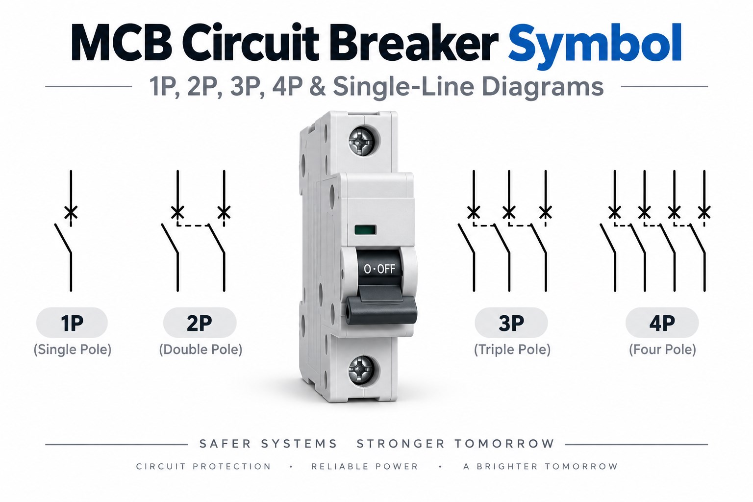
- 1P, 2P, 3P, and 4P MCB symbols mainly indicate how many conductors are switched together. 1P+N and 3P+N configurations need additional attention because the neutral pole may be switched without having the same protective function as the phase poles.
- A three-phase MCB may appear as three mechanically linked contacts on a detailed schematic, but a single-line diagram can represent the same three-pole breaker with one compact symbol.
- The symbol alone usually does not tell you the current rating, trip curve, breaking capacity, AC/DC suitability, or exact product type.
- MCB and MCCB symbols can look similar on simplified diagrams. Device tags, ratings, schedules, and specifications are often needed to tell them apart.
- When reading an electrical drawing, always use the project legend, pole annotation, breaker tag, and ratings together rather than identifying the device from shape alone.
What Does MCB Mean and What Does an MCB Do?
MCB stands for Miniature Circuit Breaker. It is an automatically operated protective switching device commonly used to interrupt a circuit when an overload or short circuit exceeds the breaker’s operating limits.
Unlike a fuse, an MCB can normally be reset after the fault has been cleared. It also provides manual switching, although its primary role in the circuit is protection rather than routine control.
Typical MCB applications include:
- Residential distribution boards
- Commercial branch circuits
- Lighting circuits
- Small motors
- Control panels
- Industrial auxiliary circuits
- Equipment power distribution
The exact protection characteristics depend on the device. Rated current, trip curve, breaking capacity, voltage rating, and pole configuration must therefore be checked separately from the schematic symbol.
What Does an MCB Circuit Breaker Symbol Mean?
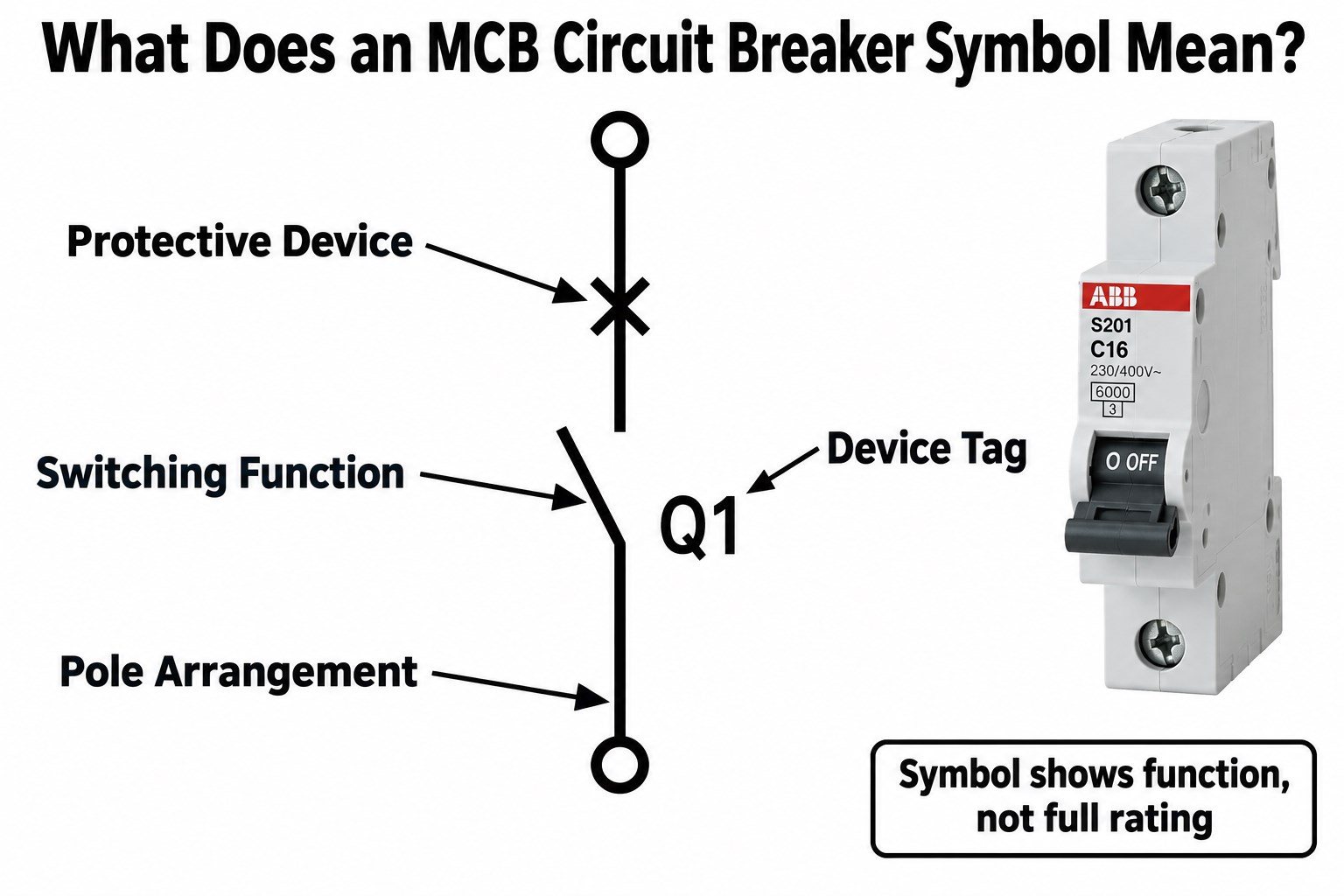
The MCB symbol meaning is that the circuit contains a protective switching device capable of automatically interrupting fault current.
Depending on the drawing style, the symbol may show a switching contact, a break in the conductor path, a protective-device qualifier, multiple mechanically linked poles, or a device tag such as CB1, QF1, or MCB1.
The graphic can help identify the function and sometimes the pole arrangement, but it usually does not provide the complete device specification. Rated current, trip curve, breaking capacity, voltage, AC/DC suitability, manufacturer, product series, and terminal arrangement normally come from annotations, schedules, or the component specification.
Is There One Standard MCB Symbol?
No. There is no single MCB graphic that appears identically in every electrical schematic, single-line diagram, and CAD library.
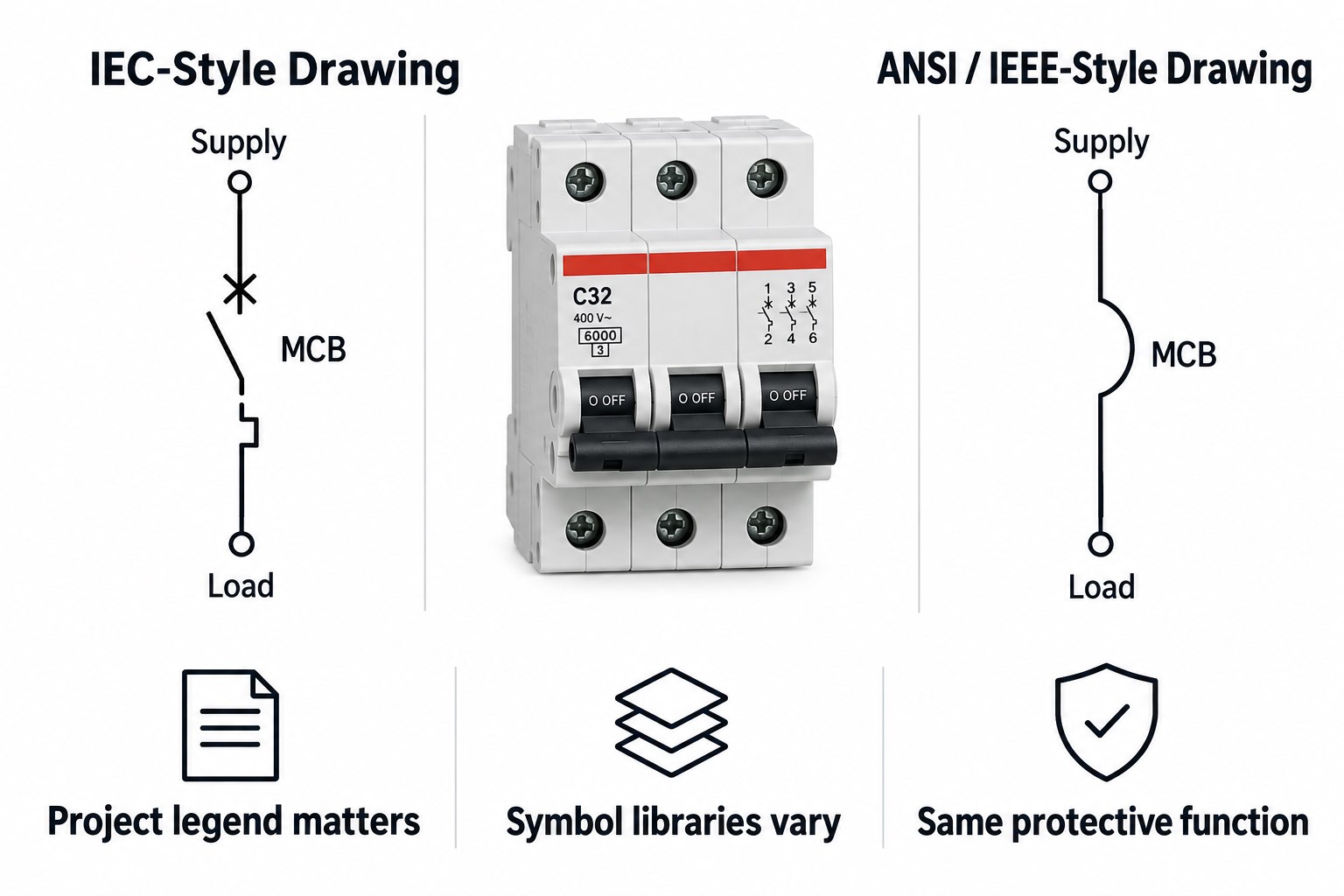
IEC 60617 provides standardized graphical symbols for electrical diagrams, including switching and protective functions. However, the symbol actually shown in a project can vary depending on how the standard is applied and how much detail the drawing needs.
Variation can come from IEC-based symbol libraries, ANSI/IEEE-style drawings, single-line diagrams, detailed control schematics, CAD software libraries, company drafting standards, and manufacturer documentation.
The correct method is therefore to check the drawing legend and project drafting standard first. A symbol should be interpreted in the context of the drawing in which it appears.
IEC vs ANSI/IEEE MCB Symbols: What Is the Difference?
IEC and ANSI/IEEE-style drawings can represent circuit-breaker functions differently, although both communicate the same basic idea: a protective device that can open the electrical path.
| Drawing Convention | Typical Characteristics |
|---|---|
| IEC | IEC 60617 graphical conventions, IEC-style device designations |
| ANSI/IEEE | North American symbol conventions and device numbering |
| Single-line diagram | Simplified representation of multiphase circuits |
| Detailed schematic | Individual contacts, coils, mechanical links, and terminals may be shown |
Neither system changes what the MCB physically does. The main risk is assuming a symbol copied from one standard must look exactly the same in another drawing. In real engineering documentation, the project legend remains the safest reference.
1P vs 2P vs 3P vs 4P MCB Symbols: What Changes?
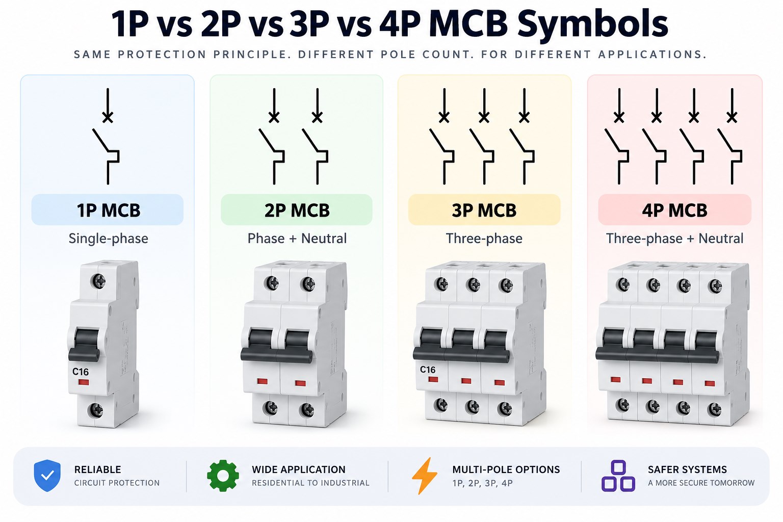
The main difference between 1P, 2P, 3P, and 4P MCB symbols is the number of conductors operated together by the breaker.
| MCB Configuration | Conductors Switched | Typical Application |
|---|---|---|
| 1P | 1 | Single-phase branch circuit |
| 2P | 2 | Phase + neutral or two-line circuit |
| 3P | 3 | Three-phase circuit |
| 4P | 4 | Three-phase + neutral |
| 1P+N | 2 | Single-phase with switched neutral |
| 3P+N | 4 | Three-phase with switched neutral |
A 1P MCB normally interrupts one live conductor. A 2 pole MCB symbol represents two mechanically linked poles operating together, while a 3P MCB mechanically links three poles for a three-phase system. A 4 pole MCB symbol adds a fourth switched path, commonly used when the neutral must also be disconnected.
However, 1P+N and 3P+N should not automatically be treated as identical to 2P and 4P protective devices. In some constructions, the neutral pole is switched but does not provide the same overcurrent protection as the phase pole.
What Does a 3-Phase Circuit Breaker Symbol Show?
A 3 phase circuit breaker symbol represents one breaker operating across all three phase conductors together.
In a detailed schematic, the drawing may show three separate contacts with a mechanical linkage between them. That linkage indicates that the poles operate together as one device.
In a single-line diagram, however, the entire three-phase circuit is represented by one line. The breaker may therefore appear as one compact symbol with annotations such as 3P, 3Ø, CB1, QF1, C32, or 10 kA.
A single line in an SLD does not mean the breaker has only one pole. Mechanical linkage shows simultaneous operation; it is not another current-carrying wire.
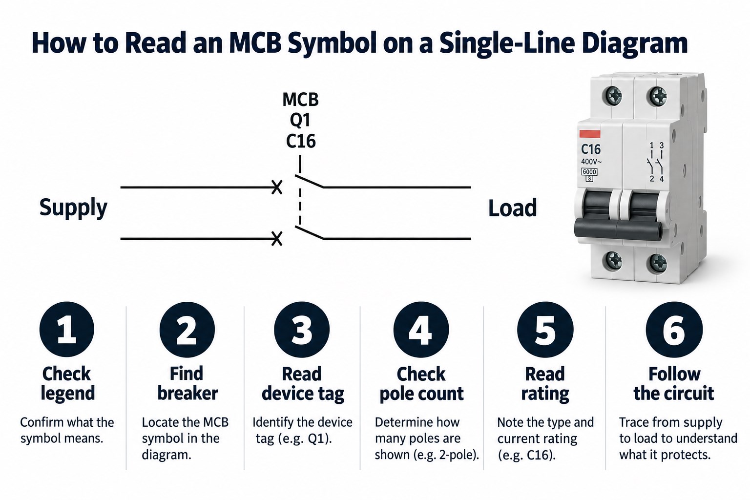
How Do You Read an MCB Symbol on a Single-Line Diagram?
Reading an MCB on a single-line diagram is easier when you follow the information in a fixed order instead of relying on the symbol shape alone.
- Check the drawing legend. Confirm what the project uses for MCBs, MCCBs, isolators, fuses, and switches.
- Locate the breaker symbol. Follow the incoming supply or feeder until you reach the protective switching device.
- Read the device tag. Common tags include MCB1, CB1, QF1, or Q1.
- Check the pole configuration. Look for 1P, 2P, 3P, 4P, 1P+N, or 3P+N.
- Read the current and trip information. A label such as C16 commonly indicates a C-characteristic 16 A MCB.
- Check breaking capacity and voltage. Values such as 6 kA or 10 kA describe short-circuit interruption capability under the applicable rating conditions.
- Follow the circuit upstream and downstream. Confirm where the breaker receives power and which load, bus, or subcircuit it protects.
What Do MCB Labels Such as C16, 3P and 6kA Mean?
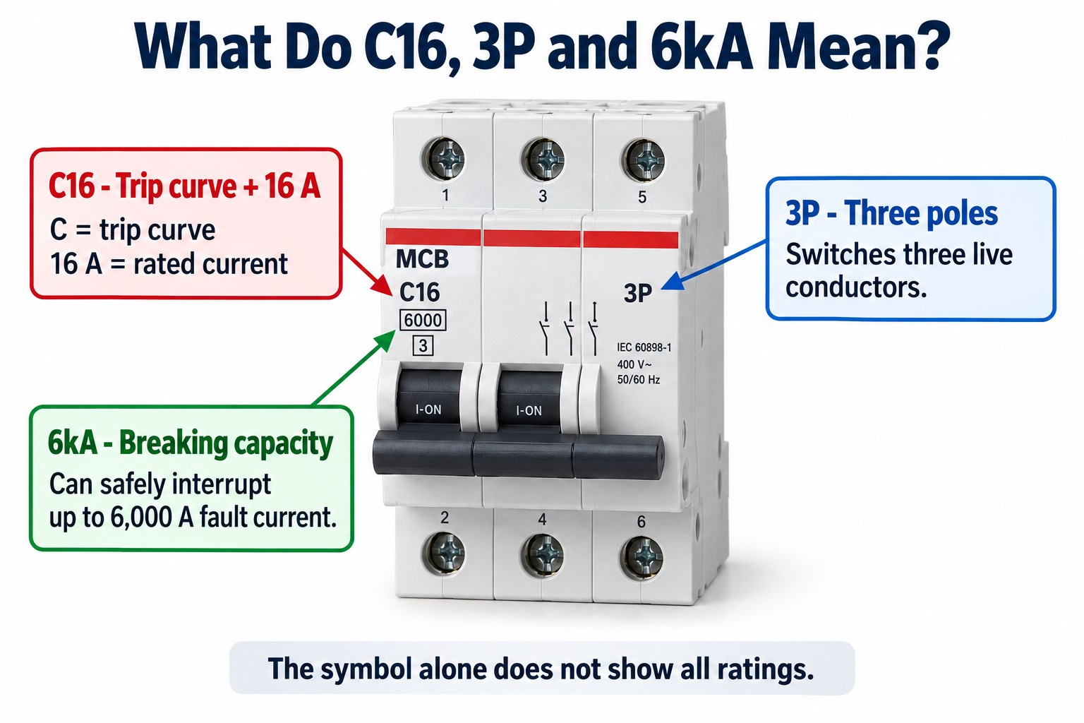
MCB labels provide electrical information that the schematic symbol itself usually cannot communicate.
| Marking | Typical Meaning |
|---|---|
| C | C-type tripping characteristic |
| 16 | 16 A rated current |
| 3P | Three-pole device |
| 6 kA | Rated short-circuit breaking capacity under the applicable rating standard |
A B, C, or D designation normally relates to the magnetic trip characteristic rather than the number of poles. Similarly, 6 kA does not mean the breaker is intended to carry 6,000 A continuously. It describes the short-circuit current the device is rated to interrupt under specified test conditions.
MCB vs MCCB Symbols: Can You Tell Them Apart by Shape?
Not always. An MCB and an MCCB can share a generic circuit-breaker symbol in simplified drawings because both perform the same basic protective switching function.
The difference may only become clear from surrounding information. Check the device tag, MCB/MCCB annotation, rated current, frame size, breaking capacity, adjustable trip settings, electronic or thermal-magnetic trip unit, equipment schedule, and manufacturer part number.
An MCCB is generally used for higher current levels and more demanding distribution applications, while an MCB is typically used for lower-current final or branch circuits. However, symbol shape alone should not be used to determine the product category.
MCB vs Fuse vs Switch Symbol: How Do You Avoid Misreading Them?
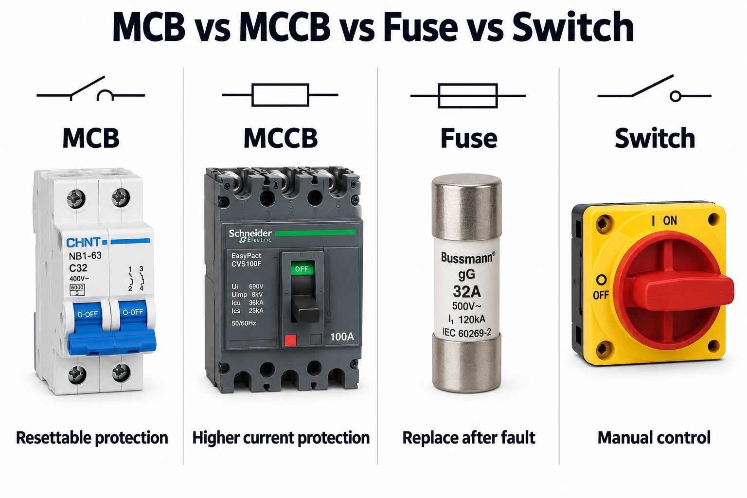
MCBs, fuses, and switches can all interrupt a circuit, but their functions are different.
| Device | Automatic Fault Protection | Resettable | Main Purpose |
|---|---|---|---|
| MCB | Yes | Yes | Overload / short-circuit protection |
| MCCB | Yes | Yes | Higher-current protective switching |
| Fuse | Yes | No | Overcurrent protection |
| Switch | Not necessarily | Yes | Manual switching |
An MCB combines switching with automatic overcurrent protection. A fuse also provides automatic protection, but once its element melts, the fuse must be replaced. A normal switch can open the circuit manually but should not be assumed to provide overload or short-circuit protection unless it is part of a protective device.
What Information Should Be Checked Beyond the MCB Symbol?
The MCB symbol identifies the device function, but selecting or verifying the physical breaker requires more information.
Engineers should check:
- Rated current
- Pole count
- Rated voltage
- AC or DC operation
- Trip characteristic
- Breaking capacity
- Frequency
- Installation category
- Terminal arrangement
- Applicable standard
- Manufacturer and part number
The same distinction matters when an MCB connects to a PCB-based control system. The schematic symbol is not the physical footprint.
A control PCB may interface with auxiliary contacts, shunt-trip coils, undervoltage release, remote actuators, current sensors, status inputs, or DIN-rail terminal blocks. Connector pitch, terminal current, creepage, clearance, relay ratings, and isolation barriers must therefore be designed from the actual hardware specification rather than from the MCB symbol shown in the system schematic.
FAQ About MCB Circuit Breaker Symbols
1. What is the full form of MCB?
MCB stands for Miniature Circuit Breaker. It is mainly used for automatic overload and short-circuit protection in lower-current electrical circuits.
2. What is the symbol of an MCB?
The exact symbol depends on the drawing standard and diagram type. IEC-based schematics, ANSI/IEEE-style drawings, and single-line diagrams may represent the breaker differently, so the project legend should be checked.
3. What is the difference between a 1P and 2P MCB symbol?
A 1P MCB operates one conductor, while a 2P MCB operates two mechanically linked conductors together.
4. What is the symbol for a 3-phase MCB?
A detailed schematic may show three mechanically linked breaker contacts. In a single-line diagram, one breaker symbol marked 3P may represent the complete three-phase device.
5. Is the MCB symbol different from the MCCB symbol?
Not necessarily. Simplified electrical drawings can use the same basic circuit-breaker symbol for both, with annotations or schedules identifying whether the device is an MCB or MCCB.
6. Can an MCB symbol tell me whether the breaker is AC or DC?
Usually not. AC/DC suitability should be confirmed from the rating annotation, project specification, and manufacturer datasheet rather than inferred from the symbol shape.
Reading an MCB Symbol on a PCB-Based Control System?
An MCB symbol can identify the protective device on the electrical schematic, but PCB design requires the actual breaker interface to be reviewed separately. Auxiliary contacts, control voltages, terminal spacing, isolation, relay outputs, and sensing circuits all affect the final board.
EBest Circuit supports industrial control PCB fabrication, DFM review, component sourcing, PCBA, and functional testing. If your control-board project interfaces with breakers, relays, contactors, or other power devices, send your Gerber files, BOM, schematic, and electrical requirements to sales@bestpcbs.com for engineering review.
You may also like



Tags: 2 pole mcb symbol, 3 phase circuit breaker symbol, 4 pole mcb symbol, mcb circuit breaker symbol, mcb symbol meaning