





An LED ALU PCB is an aluminum-backed metal-core circuit board that carries LEDs while moving heat toward a housing or heat sink. Ordering one by outline, wattage and quantity alone leaves the most important decisions undefined. Project teams should specify the dielectric, copper, aluminum base, LED footprint, mounting interface and acceptance tests as one thermal and mechanical system.

What Is an LED ALU PCB?
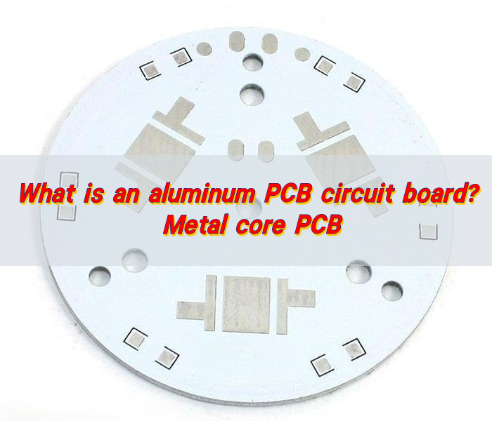
An LED ALU PCB, also called an LED aluminum PCB or LED MCPCB, normally has a copper circuit layer, a thin thermally conductive electrical insulator and an aluminum base. The LEDs are soldered to the copper pads. Heat then crosses the dielectric and spreads through the metal base before reaching the product’s heat sink or housing.
The aluminum is normally a thermal and structural layer, not an exposed circuit conductor. Copper features must remain electrically isolated from the metal base according to the design’s voltage requirements. This distinction also answers a common question, what is PCB in LED lights: it is the circuit platform that connects and supports the LEDs, and in an aluminum construction it also forms part of the heat-transfer path.
When Should You Choose LED Aluminum PCB Instead of FR-4?
Choose aluminum when the LED power density, enclosure temperature or available cooling area makes heat removal through ordinary FR-4 copper difficult. A low-power indicator board may still work well on FR-4. A dense array for a streetlight, high-bay lamp or compact optical module is more likely to need a metal-backed construction.
| Project condition | Likely starting point | Reason to verify |
|---|---|---|
| Low-power indicators with generous board area | FR-4 | Copper spreading and thermal vias may be sufficient |
| Moderate or high LED heat with direct heat-sink contact | Aluminum MCPCB | Shorter through-thickness thermal path at practical cost |
| Very concentrated heat flux or direct-thermal-path requirement | Copper-core or SinkPAD construction | Local hot-spot removal may matter more than board weight or cost |
| Electrical isolation plus demanding temperature stability | Ceramic substrate | Different insulation, thermal and mechanical trade-offs apply |
Do not select a board only because aluminum conducts heat better than FR-4. The thin dielectric can dominate the board’s through-thickness thermal resistance, while the thermal interface material, mounting pressure and heat sink govern what happens after heat reaches the metal base.
Which LED Products Benefit from an Aluminum Core?
An aluminum core is useful when the PCB can make broad, repeatable contact with a cooler part of the product. Typical uses include street and tunnel lights, high-bay fixtures, downlights, automotive exterior lamps, architectural luminaires, UV equipment and compact medical or inspection lighting.
A long LED PCB strip can use an aluminum base when the strip mounts continuously to an extrusion. A round LED PCB module may bolt to a heat sink around its perimeter. A custom LED PCB board becomes valuable when LED position must match optics, mounting holes, connectors and the enclosure. In each case, the application section of the drawing should identify how the metal back contacts the final assembly.
How Does Heat Move Through an LED ALU PCB?
Heat starts at the LED junction and passes through the package thermal pad and solder joint into the PCB copper. It then crosses the thermally conductive dielectric, spreads into the aluminum base, crosses the thermal interface material and enters the heat sink or metal housing. Airflow and the outside environment finally remove that heat.
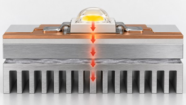
Every interface adds thermal resistance. A high-conductivity laminate cannot compensate for a voided LED solder joint, a warped board, dry contact against the heat sink or an undersized enclosure. Thermal design should therefore start with an allowable LED junction or case temperature and work backward through the complete junction-to-ambient path.
Which Material and Stack-Up Specifications Control Performance?
The quotation package should identify the values below or ask the manufacturer to propose them against defined operating conditions. A single thermal-conductivity number is not a complete stack-up.
| Specification | What it controls | What the project team should provide |
|---|---|---|
| Dielectric thermal conductivity | How readily heat crosses the insulating layer | Target or approved material family and thermal objective |
| Dielectric thickness | Thermal resistance and electrical-isolation margin | Required withstand voltage, safety spacing and test condition |
| Copper thickness | Current capacity, lateral heat spreading and etching limits | LED and driver currents plus minimum finished copper |
| Aluminum base thickness | Stiffness, heat spreading, weight and mechanical fit | Finished board thickness and enclosure constraints |
| Board flatness and outline tolerance | Heat-sink contact and optical alignment | Datum scheme, mounting features and critical dimensions |
| Surface finish and solder mask | Solderability, pad protection and optical appearance | Assembly process, exposed-pad needs and approved color |
We support MCPCB dielectric options with thermal-conductivity values of 0.8-1.0, 1.5, 2.0 and 3.0 W/m·K. These values describe the dielectric option, not the thermal conductivity of the complete assembled lamp. Final material availability and performance remain subject to the released stack-up, board dimensions, quantity and engineering review.
Which LED MCPCB Structure Should You Order?
A single-layer MCPCB is the practical starting point for many LED plates because the circuit sits on one side and the exposed metal back can contact the heat sink. It offers the shortest and simplest manufacturing path when all LED routing fits on one copper layer.
A two-layer MCPCB adds routing capacity on the component side through an additional circuit layer and dielectric construction. A double-sided structure places circuitry on both outer sides around the metal core and requires a different interconnection strategy. Multilayer constructions are possible, but the added insulation and fabrication complexity must serve a real routing or integration requirement.
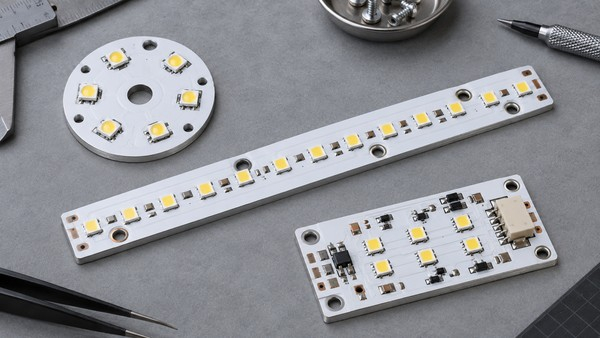
For tightly concentrated heat, a SinkPAD direct-thermal-path board may be more appropriate than a conventional metal core PCB for LED. It is not an automatic upgrade for every lamp. The LED package, thermal pad geometry, electrical isolation requirement and assembly process must be compatible with the selected construction.
How Should the LED Footprint, Copper and Polarity Be Designed?
An effective LED PCB board design begins with the package manufacturer’s land pattern and thermal-pad guidance. The exposed thermal pad should have controlled solder-paste coverage, while anode and cathode markings must remain clear after assembly. Footprints copied between LED families can create solder or optical-position errors even when the package outline looks similar.
- Place LEDs for both optics and heat spreading: avoid unnecessary clustering unless the cooler is designed for the resulting hot spot.
- Size current paths from the real drive current: include shared return paths, connectors and any on-board driver components.
- Use copper area deliberately: it spreads heat laterally before heat crosses the dielectric, but should not violate optical or creepage requirements.
- Define polarity in all production files: align silkscreen, centroid rotation, assembly drawing and test instructions.
- Keep mounting hardware clear of live copper: mounting holes, washers and metal housings need appropriate electrical clearance.
For an SMD LED PCB board, provide the BOM and centroid data when assembly is required. LED bin, color temperature, wavelength, luminous flux and forward-voltage constraints belong in the approved sourcing specification rather than in informal email notes.
How Should the Board Mount to the Heat Sink?
The aluminum back must meet a flat, clean mating surface through a controlled thermal interface material. Define the TIM type and thickness, screw locations, torque method, clip force or adhesive system before prototype approval. Mounting pressure should be distributed so the board remains flat without damaging the dielectric or solder joints.
Place mounting points close enough to control lift around hot zones, but do not crowd LED optics or copper clearances. If the board sits in an aluminum enclosure, include coating, anodizing and grounding requirements in the mechanical review. Anodized surfaces and thermal pads have electrical behavior that should be verified rather than assumed.
Which Surface Finish and White Solder Mask Fit LED Assemblies?
Surface finish should match the assembly process, pad geometry, storage plan and any wire-bond or exposed-contact requirement. ENIG, lead-free HASL, OSP and other finishes each have different flatness, cost and handling characteristics. The best choice is the one qualified for the actual component and production process.
White solder mask is common on visible lighting boards because it can support optical reflectance around the LEDs. Its color stability, coverage and curing must be controlled for the operating temperature and reflow process. White mask does not replace thermal design, and reflectance should be evaluated with the real optical system when it is a product requirement.
How Do We Manufacture and Assemble LED Aluminum PCBs?
At EBest Circuit (Best Technology), we review the Gerber data, stack-up, metal-base construction, outline, mounting plan and assembly files before release. Our MCPCB manufacturing capabilities cover single-layer, two-layer, double-sided and multilayer constructions up to 10 layers. Depending on the approved material and design, we can manufacture boards with 0.30-4.0 mm thickness, 0.15/0.15 mm minimum line/space and dimensions up to 100 × 1,300 mm. These maximum capabilities depend on material, stack-up, board dimensions, design complexity, quantity and engineering review.
Fabrication normally combines copper imaging and etching, dielectric-to-metal lamination, drilling or routing, solder-mask and surface-finish processing, profiling and electrical testing. If assembly is included, we can review the BOM and placement data, print solder paste, place SMD LEDs, control the reflow profile and perform inspection. Aluminum panels have different thermal mass from FR-4, so process settings must be developed for the actual panel and component limits.
What Inspection and Thermal Validation Should Be Defined?
Bare-board electrical testing checks opens and shorts, but it does not prove the finished lamp’s junction temperature or light output. The control plan should match the risks that matter to the customer.
- Incoming material and stack-up verification: confirm the approved laminate, copper and finished thickness.
- Dimensional inspection: check the outline, mounting holes, critical LED datums and flatness requirements.
- Electrical test: verify continuity, isolation and any specified withstand-voltage condition.
- Assembly inspection: use SPI, AOI or X-ray where the package and acceptance plan justify them.
- Functional lighting test: define current, voltage, polarity, warm-up time and pass/fail limits.
- Thermal validation: measure at agreed points in the intended mounting, ambient and duty-cycle conditions.

We can support AOI, flying-probe or universal electrical testing, copper-thickness checks and final inspection as appropriate to the build. Product-level thermal or optical acceptance requires customer-defined conditions and limits; it should not be inferred from a bare laminate data sheet.
What Drives LED PCB Board Price and Lead Time?
LED PCB board price depends on panel utilization, board shape, copper and aluminum thickness, dielectric grade, layer count, surface finish, solder-mask requirements, test coverage and quantity. Irregular outlines, long strips and tight mechanical tolerances can affect tooling and material yield even when the electrical circuit is simple.
For suitable single-layer MCPCB orders, we can support lead times as fast as 24 hours after engineering review and material confirmation. We confirm the actual lead time according to material availability, tooling, assembly, testing and order volume.
What Should You Include in an Aluminum PCB for LED Build Package?
A complete aluminum PCB for LED quotation package lets suppliers quote the same construction and reduces late changes. Include:
- Gerber or ODB++ data, fabrication drawing and stack-up;
- finished board thickness, copper weight, dielectric requirement and aluminum-base requirement;
- outline, panelization, mounting-hole details, flatness and critical dimensions;
- surface finish, solder-mask color and any reflectance requirement;
- LED power, current, operating ambient, duty cycle, heat sink and TIM description;
- BOM, centroid file, assembly drawing and LED binning requirements when PCBA is included;
- electrical, isolation, functional, optical and thermal test conditions;
- prototype quantity, production forecast, packaging and traceability needs.
For an aluminum core PCB for LED, also identify where the bare metal may contact the enclosure and whether it must be grounded or isolated. For an aluminum PCB for LED light with optics, provide the LED-to-lens datums and allowable positional tolerance.
Frequently Asked Questions About LED ALU PCBs
What is an aluminum PCB?
It is a printed circuit board that uses a metal base, usually aluminum, beneath an electrically insulating dielectric and copper circuit. The metal spreads heat and adds stiffness while the dielectric keeps the circuit electrically isolated.
Does an LED aluminum PCB eliminate the heat sink?
No. It improves the path from the LED toward the cooler, but the TIM, heat sink, enclosure and airflow must still release the heat. Some low-power products use the housing itself as the heat spreader.
Can an LED MCPCB carry the driver circuit?
Yes, when routing density, voltage spacing and thermal conditions fit the selected structure. In many products, separating the LED plate from an FR-4 control board simplifies both thermal contact and dense routing.
Is higher dielectric conductivity always better?
Not by itself. Conductivity, dielectric thickness, isolation voltage, bond reliability, material availability and cost must be considered together.
Can the same board be used for different LED wattages?
Only after checking current paths, LED footprint, heat density, driver conditions and the full cooling assembly. Matching the outline does not prove thermal compatibility.
Send a Build-Ready LED ALU PCB Package
A reliable LED ALU PCB order starts with the complete thermal path, not a material name alone. Send your Gerber files, stack-up, BOM and placement data, mechanical drawing, operating conditions and test requirements to sales@bestpcbs.com. We will review the construction and identify the points that need confirmation before prototype or production release.
You may also like


Tags: LED ALU PCB, LED aluminum pcb, LED MCPCB, led pcb design, Metal Core PCB