





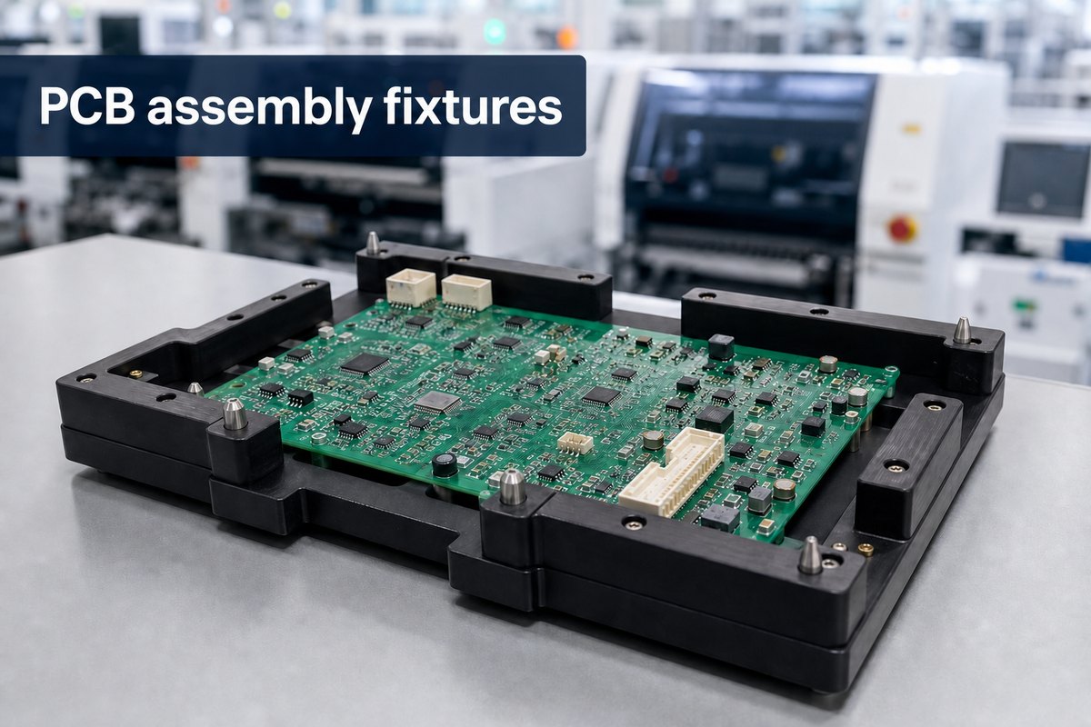
PCB assembly fixtures help buyers keep thin, flexible, double-sided, or irregular boards stable through printing, placement, soldering, inspection, and handling. Applied to a defined process risk, they can improve repeatability and protect yield without adding tooling that the build does not need.
EBest Circuit (Best Technology) evaluates fixture support as part of the PCB assembly plan—not as a stand-alone product sale. Buyers can send Gerber files, BOM, assembly drawings, pick-and-place data, panel information, and forecast quantities to sales@bestpcbs.com for a build-specific review.
When Are PCB Assembly Fixtures Necessary?
Not every PCB assembly needs a dedicated fixture. A rigid, well-panelized board may run reliably with standard conveyor support. Fixture support becomes worth evaluating when the board or process cannot consistently hold the position, flatness, clearance, or thermal exposure required for stable production.
You may need fixture support when:
- A thin rigid PCB bows: Deflection during printing or placement can affect paste transfer and component position.
- An FPC or rigid-flex area moves: Unsupported material can wrinkle, lift, or shift beneath connectors and dense component areas.
- A double-sided assembly needs underside clearance: Previously mounted components may require protection during the second-side process.
- An irregular outline is difficult to transport: Cutouts, narrow rails, or an unusual center of gravity can make standard conveyor support unreliable.
- Tall, heavy, press-fit, or off-board parts need restraint: Controlled support may be required while force or heat is applied.
- Only selected joints should contact solder: A wave or selective soldering operation may need precise exposure and shielding.
The decision should start with an observable problem: what moves, bends, heats unevenly, or loses alignment, and at which operation? This prevents a fixture from becoming an unexplained tooling charge and ties it to a manufacturing risk the buyer can verify.
How Do PCB Fixtures Reduce Assembly Defects?
PCB fixtures reduce defects by removing avoidable mechanical variation. Their contribution depends on where that variation enters the process:
- During solder paste printing: Support beneath vulnerable areas can limit local deflection and help the stencil, PCB, and paste deposits remain in the intended relationship.
- During component placement: A stable board is less likely to flex or shift as components are positioned.
- During reflow, wave, or selective soldering: The fixture can maintain orientation and flatness, restrain a connector, or shield regions that should not contact molten solder.
- During handling and transfer: A carrier can reduce repeated bending, edge damage, and stress on fragile or already mounted parts.
For the buyer, the expected result should be stated in practical terms: fewer opens caused by incomplete contact, less bridging linked to movement or poor solder presentation, more consistent positioning, or lower handling damage.
What a fixture cannot fix: A fixture does not compensate for incorrect pad design, unsuitable paste volume, component coplanarity problems, inaccurate placement data, or an unstable thermal profile. It should remove a defined mechanical variable so the remaining process can be validated more clearly.
Which Boards Benefit Most from Assembly Fixtures?
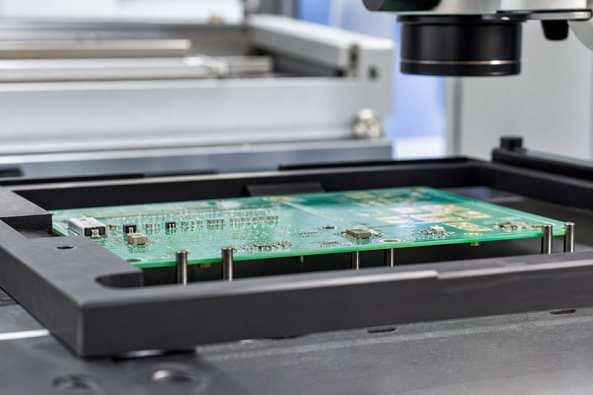
Assembly fixtures usually add the most value when the board itself does not provide a stable manufacturing platform. Buyers should pay particular attention to:
- Thin rigid PCBs: Low stiffness can allow bowing under a stencil, placement nozzle, clamp, or conveyor support.
- Flexible and rigid-flex circuits: Unsupported areas can move, wrinkle, or lift, especially near connectors or dense component zones. Our flex PCB assembly guide explains additional handling considerations.
- Double-sided assemblies: Bottom-side components may need clearance and protection during the second-side process.
- Irregular or routed outlines: Cutouts and narrow rails can make standard line support unreliable.
- Boards with press-fit, tall, heavy, or off-board parts: The assembly may need controlled support while force is applied or a connector is soldered.
- Selective soldering candidates: Closely spaced keep-out areas or heat-sensitive parts may require controlled exposure and shielding. See our selective wave soldering overview for process context.
The decision should be based on process risk, not order volume alone. A small prototype lot can justify a simple carrier when one unstable operation threatens expensive components or a critical schedule. A high-volume board may not need custom support when its panel and process are already robust.
How Do Fixtures Support SMT and Wave Soldering?
The fixture must match the production operation. A carrier that works for printing or placement is not automatically suitable for reflow, wave soldering, or selective soldering.
For SMT assembly:
- Keep thin, flexible, or irregular boards flat enough for paste printing and placement.
- Leave fiducials, tooling features, printed pads, and component locations accessible.
- Secure the board without creating stress or interfering with clamps, nozzles, and components.
- Tolerate the intended reflow temperature and repeated production cycles.
For wave or selective soldering:
- Expose the intended through-hole joints to solder.
- Shield SMT components, board areas, and underside features that should not contact the solder wave.
- Maintain sufficient clearance around components and solder apertures.
- Support the intended solder-flow direction without starving or disturbing nearby joints.
- Fit the conveyor, loading method, and production equipment.
What buyers should confirm: Ask which operation the fixture supports, which areas it exposes or protects, how the board is located and retained, and how thermal compatibility and first-article performance will be checked. The quotation should explain the risk being controlled—not simply include “fixture” as an unexplained line item.
What Should Buyers Confirm About Fixture Cost and Reuse?
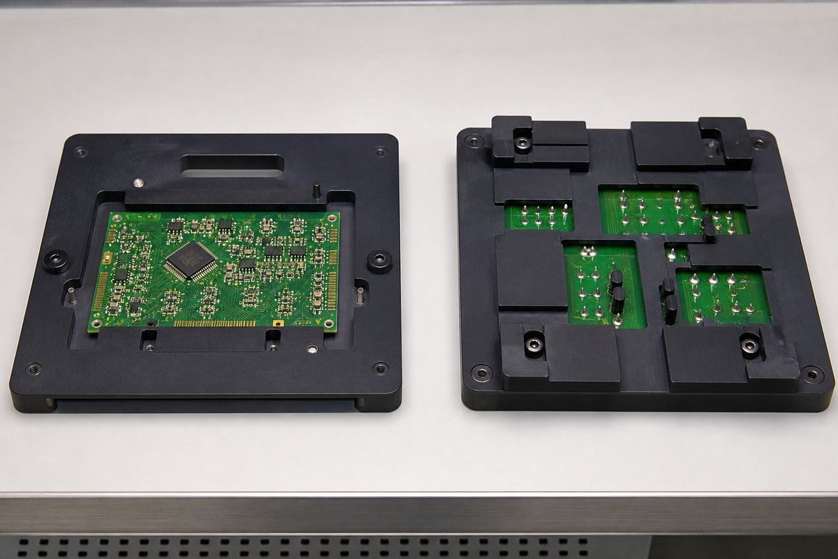
Fixture cost is easier to evaluate when the quotation defines the purpose of the tool and how it will be managed.
Before approving the fixture cost, confirm:
- the process step and defect risk the fixture is intended to control;
- whether the price covers design, fabrication, validation, and later adjustment;
- whether one fixture is enough for the required throughput or several are needed;
- who owns the fixture, where it will be stored, and how it will be identified; and
- expected service life, cleaning, inspection, and replacement criteria.
Before reusing the fixture, confirm:
- the PCB, panel, BOM, and assembly-drawing revision it was designed for;
- whether the board outline, thickness, locating holes, or panel rails have changed;
- whether component locations, keep-out areas, support points, or solder apertures have changed; and
- whether the fixture remains clean, undamaged, dimensionally stable, and traceable to the correct program.
Reuse should never be assumed from the product name alone. Even a small revision near a locating pin, clamping area, support point, or aperture can make an existing fixture unsuitable. The repeat-order review should record a clear disposition: reuse, modify, or replace.
For a new program, compare fixture cost with first-article needs, expected order frequency, rework exposure, and schedule risk. A low-cost tool that cannot be matched to the correct revision is not economical; a well-controlled reusable tool may support multiple repeat orders.
FPC Connector Soldering: A Fixture Decision Case
An anonymized internal manufacturing case illustrates how the decision should work.
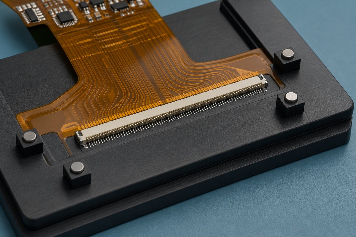
The problem: An FPC with a long connector did not remain sufficiently flat during solder paste contact. One end of the connector was at risk of not contacting the paste as intended. The issue was the mechanical presentation of the joint—not simply a request for “better soldering.”
The fixture decision: The corrective route evaluated rigid composite support beneath the flexible circuit together with magnetic retention to control position and flatness. This was an evaluated manufacturing response, not proof that one material or fixture design will solve every FPC problem.
What the buyer should provide:
- unsupported FPC zones and the connector span;
- stiffener locations and board thickness information;
- panel or carrier orientation;
- component and clamp keep-out areas; and
- photos or inspection evidence showing the existing contact problem.
What should be validated: The supplier should check flatness, retention force, component clearance, thermal compatibility, loading and unloading, and first-article soldering results before the solution is treated as production-ready.
The value of the fixture is not its material name. Its value is that a known mechanical problem is converted into a controlled manufacturing response with a defined reason, revision, and validation point.
Why Choose EBest Circuit for PCB Assembly with Fixture Support?
Buyers rarely want another tooling supplier to manage. They want a PCB assembly partner that can recognize when mechanical support affects manufacturability, coordinate the required fixture with production, and keep the decision connected to the approved product revision.
EBest Circuit supports that objective through:
- One coordinated manufacturing handoff: PCB data, BOM, placement information, assembly drawings, and fixture requirements can be reviewed together.
- Build-specific DFM review: The review connects board construction, panel stability, component clearance, soldering route, and the risk the fixture must control.
- Fixture and process coordination: Support features are considered alongside SMT, wave or selective soldering, handling, inspection, and first-article requirements.
- Revision control for repeat orders: The approved data set can be checked before an existing fixture is reused, modified, or replaced.
- Practical inspection planning: Mechanical support is paired with appropriate assembly checks rather than presented as a guarantee that every solder joint will automatically be acceptable. Our PCB assembly first article inspection checklist provides a structured starting point.
- Traceability discussions at RFQ stage: Where the program requires it, buyers can define material and process records before production. See our PCB assembly traceability RFQ checklist for the questions to raise.
What to send for review: Gerber files, BOM, assembly drawings, pick-and-place data, panel details, board thickness, order quantity, and expected repeat volume. If an existing process already shows bowing, shifting, incomplete contact, bridging, or handling damage, include photos or inspection evidence.
Send the project package to sales@bestpcbs.com. EBest Circuit can then assess whether fixture support belongs in the assembly plan, what it must control, and what should be confirmed before quotation and production.
FAQs About PCB Assembly Fixtures
Are PCB assembly fixtures required for every order?
No. They are most useful when a defined mechanical, thermal, clearance, or handling risk cannot be controlled reliably by the board, panel, or standard production equipment. The need should be justified against the actual process.
Can one fixture be used for both prototypes and volume production?
Sometimes. A prototype carrier may be designed for learning and manual handling, while volume production may require greater durability, multiple identical tools, faster loading, or compatibility with automated equipment. Confirm the production purpose before assuming the same design is suitable.
Who owns and stores a custom fixture?
Ownership and storage terms vary by supplier and quotation. Buyers should document ownership, tool identification, storage location, retention period, maintenance responsibility, and what happens if the program transfers or becomes inactive.
Can a PCB assembly fixture be reused after a board revision?
Only after a compatibility review. Changes to the outline, thickness, panel rails, component positions, keep-out areas, locating holes, or solder apertures can affect fit and function even when the product name remains the same.
What files help a supplier evaluate fixture requirements?
Provide Gerber data, fabrication notes, BOM, centroid or pick-and-place data, assembly drawings for both sides, panel information, board thickness, expected quantity, and the intended soldering route. Add photos, samples, or defect records when the request is driven by an existing manufacturing issue.
Not sure whether your project needs PCB assembly fixtures? Send your Gerber files, BOM, assembly drawings, pick-and-place data, panel details, order quantity, and any existing defect photos to sales@bestpcbs.com. EBest Circuit can review where fixture support may add value and clarify the manufacturing checks, tooling decision, and next steps before quotation.
You may also like

Tags: PCB Assembly Fixtures, PCB Assembly Tooling, PCB Fixtures