





An automotive IR illuminator aluminum PCB carries current to infrared emitters, provides a stable mounting platform and transfers heat away from the LED array in driver monitoring and other in-cabin sensing systems. The PCB design has to work with the IR emitter package, current profile, camera field of view, beam pattern and module geometry.
Are you worried about these automotive IR illumination problems?
- The IR LED array runs too hot during pulsed or continuous operation.
- The camera sees uneven IR illumination, with bright and weak areas across the field of view.
- The prototype works, but LED position, PCB construction or assembly quality becomes difficult to keep consistent in production.
As a professional one-stop PCB and PCBA service provider, EBest Circuit supports automotive IR illuminator aluminum PCB fabrication, component sourcing, PCB assembly, prototyping and mass production. Our solutions include:
- Control Current and Heat Around the Emitters
Match copper geometry, thermal dielectric and metal-core construction to the actual LED current and emitter layout. - Maintain Optical and Mechanical Alignment
Control LED position, orientation, PCB dimensions and mounting features so the illuminator fits the camera module as designed. - Carry the Approved Build Into Production
Keep the validated PCB construction and assembly requirements consistent when moving from prototypes to volume manufacturing.
For an automotive camera illumination aluminum PCB or in-cabin sensing IR aluminum PCB, send your Gerber files, IR LED datasheet and project requirements to sales@bestpcbs.com for a quotation.
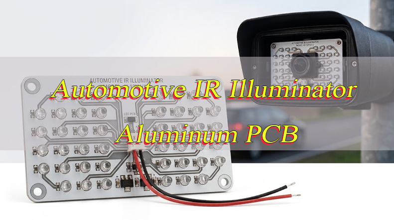
What Is an Automotive IR Illuminator Aluminum PCB and Where Is It Used in In-Cabin Sensing?
An automotive IR illuminator aluminum PCB is a metal-based PCB used to mount and power infrared LEDs in automotive camera and in-cabin sensing modules. Its main functions are to carry LED current, hold the emitters in the required positions and transfer heat away from the IR LED array.
The board is part of the sensing module rather than a stand-alone lighting circuit. IR LED position, beam direction, camera location and housing geometry all affect how the illuminator performs after installation.
Depending on the optical design, the module may use 850 nm or 940 nm IR emitters.
Typical applications include:
- Driver Monitoring Systems (DMS): Supports imaging of the driver’s face, eyes and head position.
- Occupant Monitoring Systems (OMS): Provides IR illumination across passenger and seating areas.
- Child Presence Detection: Supports camera-based sensing in low visible-light conditions.
- Interior and Gesture Monitoring: Used in overhead consoles, displays and interior camera modules.
- Eye-Tracking Systems: Provides controlled illumination around the driver’s eyes and facial area.
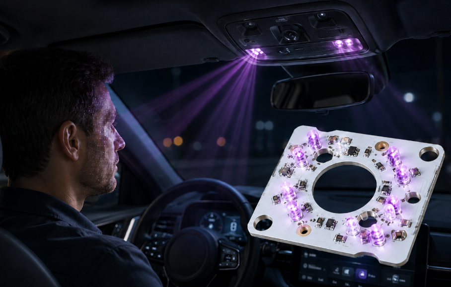
How Should an In-Cabin Sensing IR Aluminum PCB Handle LED Current and Heat?
An in-cabin sensing IR aluminum PCB needs to be designed around the actual LED current waveform, particularly when the emitters operate in pulsed or strobed modes.
Average current alone does not describe the load on the PCB. During a high-current pulse, the traces, pads, connectors and solder joints may carry a much higher instantaneous current.
- Size Current Paths for Peak Current
Use the actual pulse current when setting trace width and copper area. Narrow conductors increase resistance, voltage drop and localized heating. - Keep High-Current Paths Short
Reduce unnecessary distance between the IR LED driver and emitter array. Shorter paths lower resistive loss and make current delivery easier to control. - Provide Enough Copper Around the Emitters
Adequate copper supports current carrying and helps spread heat away from concentrated emitter areas. - Avoid Excessive Emitter Clustering
Several high-current IR LEDs placed in a small area can create a localized thermal load. Their spacing needs to work for both optical coverage and heat distribution. - Include Driver Losses When the Driver Shares the PCB
If the driver is mounted on the same automotive IR LED PCB, its losses become part of the total thermal load. - Define the Pulse Profile
Provide peak current, pulse width and duty cycle during PCB review. These values describe the operating condition more accurately than a single nominal wattage.
How Should Automotive IR LED PCB Layout Support Camera Alignment and Uniform Illumination?
An automotive IR LED PCB layout needs to match the camera field of view and the required illuminated area. LED position, spacing, orientation and beam direction can all affect the image captured by the camera.
- Match the IR Beam to the Camera Field of View
A narrow beam may leave weak areas near the edges of the image. A beam that is too wide sends part of the IR output outside the useful sensing region. - Control IR LED Orientation
Directional or asymmetric emitters need the correct rotation on the PCB. A component can be electrically correct and still illuminate the wrong area. - Distribute Emitters Across the Required Region
Poor spacing can create excessive intensity in one area while leaving other parts of the camera image under-illuminated. - Use Stable Mechanical References
Mounting holes, board edges and locating features need to match the camera or illuminator housing so the same optical alignment can be reproduced during assembly. - Keep the Optical Path Clear
Screws, connectors, shields and tall components should not interfere with the IR beam. - Include Secondary Optics in the Mechanical Layout
When the module uses lenses, light guides, diffusers or optical windows, their position and tolerances need to be coordinated with the PCB.
How Should Temperature, Vibration and Long Operating Cycles Affect Automotive IR PCB Design?
Automotive IR modules can experience repeated temperature changes, vibration and high-current emitter pulsing. These conditions affect solder joints, mounting features and the long-term stability of the PCB assembly.
- Operating Temperature
PCB materials, solder mask, surface finish and assembly materials need to suit the intended module environment. - Thermal Cycling
Repeated heating and cooling places mechanical stress on solder joints and interfaces around high-current emitters. - PCB Mechanical Support
Large connectors and unsupported board sections should not transfer unnecessary mechanical load to the IR LED solder joints. - Mounting-Hole Accuracy
The PCB should fit the housing without being forced or bent during installation. Poor hole positioning can introduce mechanical stress into the finished module. - Component Retention
Larger components and connectors may require additional mechanical support where vibration is expected. - Repeated Pulsed Operation
High-current strobing creates recurring electrical and thermal loading. The current path and solder joints need to remain stable under the intended operating profile.
What Steps Are Used to Manufacture and Assemble an Automotive IR Illuminator Aluminum PCB?
An automotive IR illuminator aluminum PCB requires controlled fabrication and assembly so the emitter positions, current paths and approved metal-core construction remain consistent.
Step 1: Review the Design and IR LED Requirements
Check the IR LED part number, wavelength, footprint, polarity, orientation, peak current, copper weight, PCB thickness, thermal dielectric, mounting features and surface finish before production starts.
Step 2: Prepare the Metal-Core Laminate
Use the approved copper, dielectric and aluminum construction. A material change can affect thermal performance, finished thickness and mechanical fit.
Step 3: Form the Copper Circuit
Image and etch the IR LED pads, high-current paths and supporting circuitry. Trace width and spacing need to remain compatible with the selected copper weight.
Step 4: Drill and Profile the PCB
Produce mounting holes, slots and the finished board outline from the mechanical drawing. These features may directly control the position of the illuminator inside the camera housing.
Step 5: Apply Solder Mask and Surface Finish
Keep IR LED pads and other solderable areas correctly exposed. The selected surface finish needs to suit the component package and assembly process.
Step 6: Print Solder Paste
Match stencil openings and solder-paste volume to the IR LED package. Poor paste control can lead to uneven package seating after reflow.
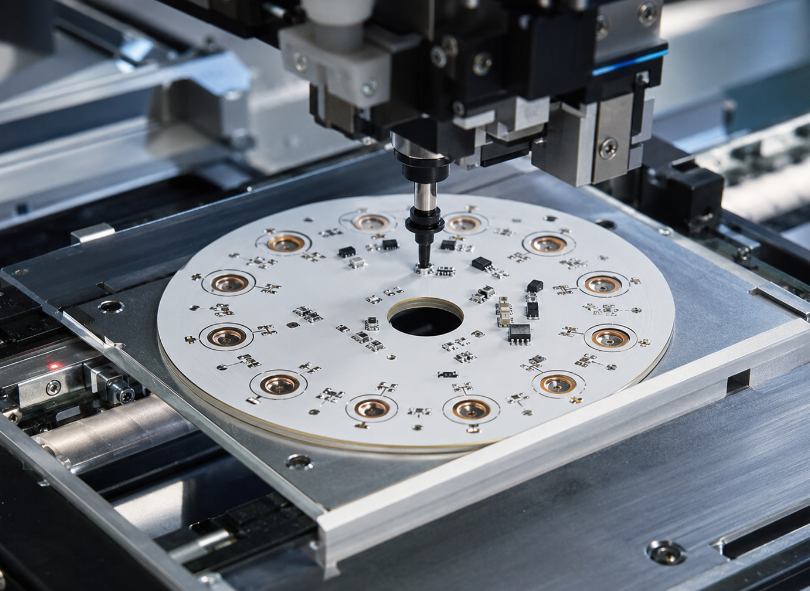
Step 7: Place the IR LEDs
Control X/Y location and component rotation. Placement accuracy is especially important for directional or asymmetric emitters.
Step 8: Complete Reflow Soldering
Use a reflow profile suitable for the selected components. After soldering, check for poor wetting, package tilt, insufficient solder and other visible defects.
Step 9: Verify the Finished Assembly
Check IR LED polarity, electrical operation, current behavior and mechanical fit before the assembly moves to the next production stage.
What Steps Are Used to Inspect and Test Automotive IR Illuminator PCBs?
Inspection should concentrate on the characteristics that can affect current delivery, IR LED alignment, thermal transfer and final module operation.
Step 1: Verify PCB Construction
Check the aluminum base, thermal dielectric, copper thickness and finished PCB thickness against the approved build.
Step 2: Check Critical Dimensions
Inspect the board outline, mounting holes, slots and locating features used to position the illuminator inside the module.
Step 3: Inspect Circuit and Surface Quality
Use visual inspection and AOI where applicable to identify opens, shorts, damaged pads, contamination and solder-mask defects.
Step 4: Perform Electrical and Insulation Testing
Verify circuit continuity and electrical isolation between the conductive circuit and metal base.
Step 5: Verify IR LED Placement
Check the emitter part number, polarity, X/Y position and rotation against the approved assembly data.
Step 6: Inspect Solder Joints
Review solder wetting and package seating. A tilted IR emitter can affect both heat transfer and beam direction.
Step 7: Perform Functional Current Testing
Operate the assembly under the defined electrical conditions and check LED switching, current delivery and supporting circuit operation.
Step 8: Check Thermal Performance
For higher-current arrays, test the PCB under representative operating conditions. Pulsed designs need an appropriate peak current and duty cycle during validation.
Step 9: Verify Optical Output When Required
When the project includes optical acceptance criteria, test the illuminator using the specified camera, IR sensor or optical fixture rather than relying on visual inspection.
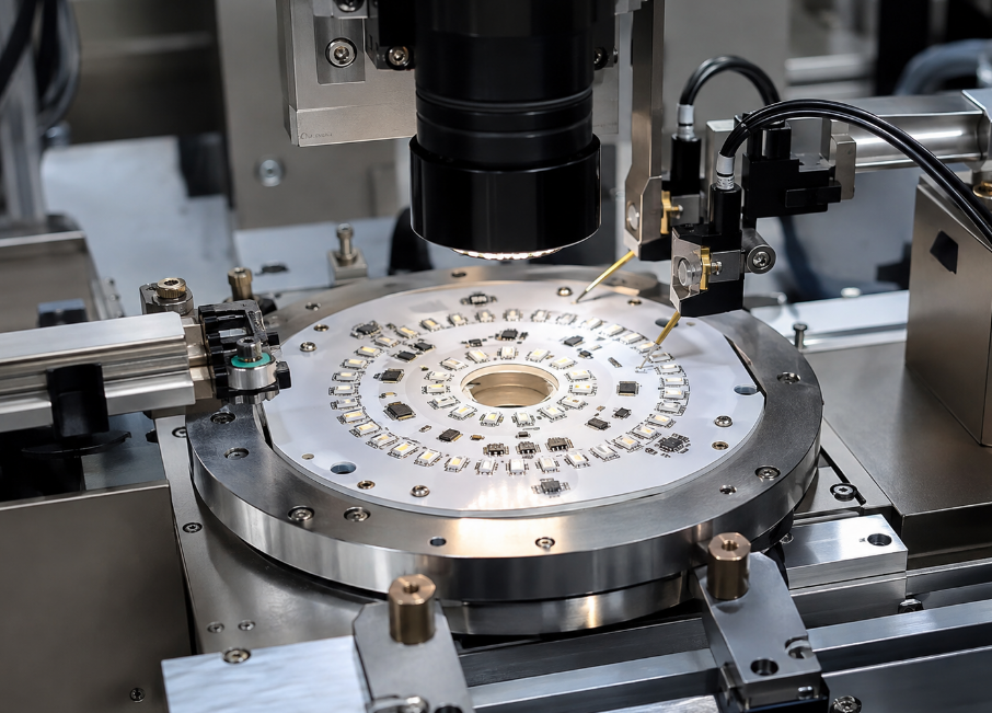
What Automotive IR Aluminum PCB Manufacturing Capabilities Can We Provide?
The table below summarizes our main MCPCB manufacturing capabilities for automotive IR illuminator PCB projects.
| Item | Capabilities |
|---|---|
| Maximum Layer Count | Up to 10 layers |
| PCB Thickness | 0.3–4.0 mm |
| Maximum Board Size | Up to 610 × 1220 mm (24 × 48 in.) |
| Copper Weight | 0.5–10 oz |
| Minimum Trace / Space | 0.15 / 0.15 mm (6 / 6 mil) |
| Minimum Hole Diameter | 0.30 mm (12 mil) |
| Minimum Punch Hole Diameter | 3.0 mm (0.12 in.) |
| Minimum Hole Spacing | 0.40 mm (16 mil) |
| Maximum Aspect Ratio | 12:1 |
| Minimum Solder Pad Diameter | 0.40 mm (16 mil) |
| Thermal Conductivity | 0.8–1.5 W/m·K standard; 2.0–6.0 W/m·K high thermal conductivity |
| Warp and Twist | < 0.75% |
| Flammability | UL 94V-0 |
| Thermal Stress | 6 × 10 sec at 288°C |
| Surface Finish | ENIG, Flash Gold, Hard Gold, Selective Gold Plating, HASL, Lead-Free HASL, OSP, Immersion Silver, Immersion Tin |
Case Study: Automotive IR Illuminator Aluminum PCB From Prototype to Production
Project Background
An in-cabin camera module required a compact automotive IR illuminator aluminum PCB for a high-current IR emitter array. The PCB had to fit the camera-module housing while holding the emitters in the positions defined by the optical design.
Project Requirements
The PCB needed to:
- Carry the specified pulsed LED current
- Keep IR emitter position and polarity consistent
- Transfer heat into the metal substrate
- Match the camera-module mounting geometry
- Fit within the available module space
- Support both prototype validation and repeat production
Our Solution
EBest Circuit reviewed the IR LED datasheet, PCB layout and mechanical drawing before prototype fabrication.
The project focused on:
- Matching IR LED footprints and package orientation
- Reviewing copper weight and high-current trace geometry
- Selecting the required thermal dielectric and aluminum construction
- Controlling board outline and mounting-hole positions
- Maintaining IR LED placement accuracy during assembly
- Checking LED seating and solder joints after reflow
- Keeping the validated PCB construction unchanged for production
Results
Prototype validation confirmed:
- Correct IR LED placement and polarity
- Stable mechanical fit inside the camera module
- Controlled current paths for the emitter array
- Consistent heat transfer into the metal base
- A repeatable PCB and assembly specification for production
What Files and Specifications Are Required for an Automotive IR Illuminator Aluminum PCB Quote?
For an automotive IR illuminator aluminum PCB quote, provide the available PCB files, assembly data and key IR LED requirements.
PCB Fabrication:
- Gerber files
- NC drill files
- Mechanical drawing
- PCB dimensions and thickness
- Copper weight
- Aluminum thickness
- Thermal conductivity requirement
- Surface finish
- Quantity and special tolerances
PCB Assembly:
- BOM
- Pick-and-place file
- Assembly drawing
- IR LED part number and datasheet
- Polarity and orientation requirements
- Functional-test requirements
IR and System Requirements:
- IR wavelength, such as 850 nm or 940 nm
- Continuous or pulse current
- Pulse width and duty cycle
- Number of IR emitters
- IR LED beam angle
- Camera field of view
- Operating temperature
- Optical acceptance requirements, if applicable
If some specifications are still open, send the available project files first for review.
Why Choose EBest Circuit for Automotive IR LED PCB Manufacturing?
EBest Circuit has more than 20 years of PCB manufacturing experience and supports projects from prototype fabrication to component sourcing, PCB assembly and mass production. Metal-based PCB / MCPCB is included in our PCB product range.
- Reduce Supplier Coordination
Keep PCB prototyping, MCPCB fabrication, component sourcing and PCB assembly within one project instead of managing several separate suppliers. This simplifies communication when the IR LED, PCB and assembly requirements need to be reviewed together. - Keep Prototype and Production Builds Consistent
The approved PCB construction, IR LED orientation and assembly requirements can stay within the same manufacturing route as the project moves from engineering samples to volume production, reducing unnecessary changes between stages. - Support Automotive Project Requirements
EBest Circuit holds IATF 16949, together with ISO 9001:2015, ISO 13485:2016 and AS9100D, providing an established quality-management framework for projects with different industry requirements. - Handle Thermal PCB Requirements in One Manufacturing Source
Because metal-based PCB / MCPCB is part of our PCB manufacturing range, automotive IR illuminator projects can be reviewed and produced without moving the thermal PCB portion to a separate supplier. - Scale From Engineering Samples to Ongoing Production
EBest Circuit has approximately 260,000 sq. ft. (28,900 m²) of monthly PCB manufacturing capability and completes more than 1,000 different boards, supporting both prototype programs and continuing production demand. - Shorten Lead Time for Eligible Urgent Builds
Expedited service is available for qualifying projects, with eligible urgent boards capable of shipment within 24 hours. Final lead time depends on the PCB construction and project requirements.
For an automotive IR illuminator aluminum PCB used in DMS, OMS or another in-cabin sensing system, send your Gerber files, BOM, IR LED datasheet and mechanical drawing to sales@bestpcbs.com for a quotation.
FAQs About Automotive IR Illuminator Aluminum PCBs
Q1: Should high-power automotive IR LEDs use a constant-current driver?
A1: In most high-power designs, yes. Controlled current provides more predictable emitter output and prevents excessive LED current. The operating point should follow the selected IR LED and driver specifications.
Q2: Why are IR LEDs often operated in pulsed mode in DMS modules?
A2: Pulsed operation allows the illumination period to be coordinated with camera exposure while reducing average power compared with continuous operation. The PCB still needs to carry the full peak current during every pulse.
Q3: Is 940 nm completely invisible inside the vehicle?
A3: Not under every operating condition. 940 nm generally produces less visible red glow than 850 nm, which is one reason it is commonly considered for in-cabin sensing.
Q4: Can one IR illuminator PCB be used for both DMS and OMS?
A4: Yes, if the optical design covers both sensing regions. Emitter position, beam angle and camera field of view need to be designed together, rather than simply increasing the number of IR LEDs.
Q5: Can an IR illuminator aluminum PCB include connectors and temperature sensors?
A5: Yes. Connectors, thermistors or other monitoring components can be integrated when routing space and assembly requirements allow. Their location should not interfere with the IR optical path.
Q6: Can FR4 be used for an automotive IR emitter array?
A6: It can be suitable for lower thermal loads. A metal-core PCB becomes more useful when multiple high-current IR emitters concentrate heat in a limited board area.
Q7: Does IR emitter binning matter when sourcing components?
A7: It can. Radiant output, wavelength and electrical characteristics may vary by bin or part specification. If the optical design depends on a defined emitter range, the approved sourcing specification should identify it clearly.
Q8: Can near-infrared output be checked visually during production?
A8: No. Visible appearance is not a reliable measurement of near-infrared radiant output. Use an IR-sensitive camera, photodetector or defined optical test fixture when optical verification is required.
Q9: Should the optical window be included during final illumination testing?
A9: Yes when it is part of the finished optical path. Window material, coating, geometry and position can affect the IR energy reaching the camera or sensing area.
Q10: What information should be controlled after prototype approval?
A10: Keep the approved IR LED part number, package orientation, PCB construction, mechanical references and assembly requirements under revision control so production builds remain consistent with the validated design.
Conclusion
An automotive IR illuminator aluminum PCB has to carry high-current IR emitter loads while keeping LED position, mechanical fit and thermal performance consistent inside the sensing module. Current routing, emitter placement, mounting accuracy and assembly control all influence the final result.
EBest Circuit supports metal-core PCB manufacturing, prototyping, component sourcing, PCB assembly and mass production. For an automotive camera illumination aluminum PCB, in-cabin sensing IR aluminum PCB or automotive IR LED module, send your project files and requirements to sales@bestpcbs.com for a quotation.
You may also like
Tags: aluminum pcb, Automotive IR Illuminator Aluminum PCB, IR Aluminum PCB, IR Illuminator Aluminum PCB