





A microcontroller unit is the control center of many electronic products. It reads signals, runs firmware, controls outputs, communicates with sensors or interfaces, and decides how the product responds during real use. MCU-based boards are common in industrial controllers, IoT devices, smart modules, power products, medical electronics, automotive electronics, test equipment, and consumer devices.
For PCB and PCBA projects, the microcontroller is not just one component on the BOM. It affects PCB layout manufacturability, power stability, crystal placement, reset circuits, programming access, SMT accuracy, inspection, firmware loading, testing, and final delivery. EBest Circuit (Best Technology) supports MCU-based projects with PCB fabrication, BOM sourcing, complete SMT PCB assembly, PCBA DFM review, customer-provided firmware programming, functional test coordination, and small-batch production.
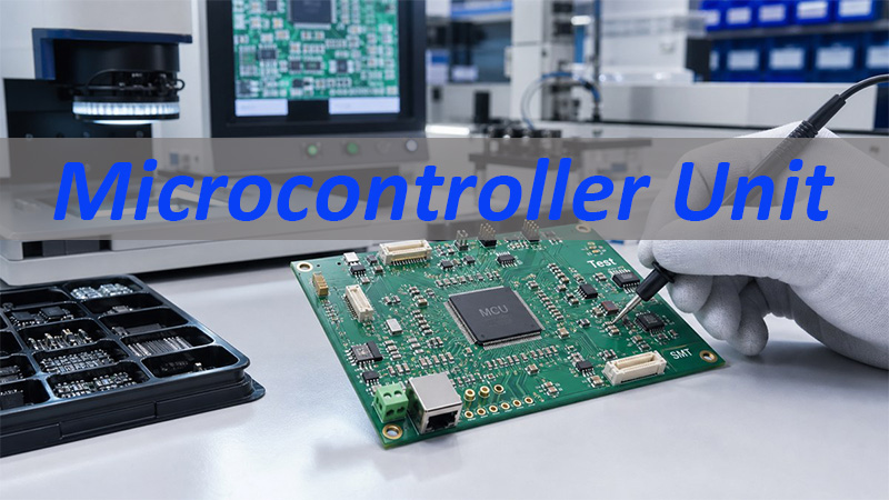
What Is a Microcontroller Unit in Electronics?
A microcontroller unit, often called an MCU, is an integrated circuit that usually includes a processor core, memory, I/O pins, timers, communication interfaces, and control functions.
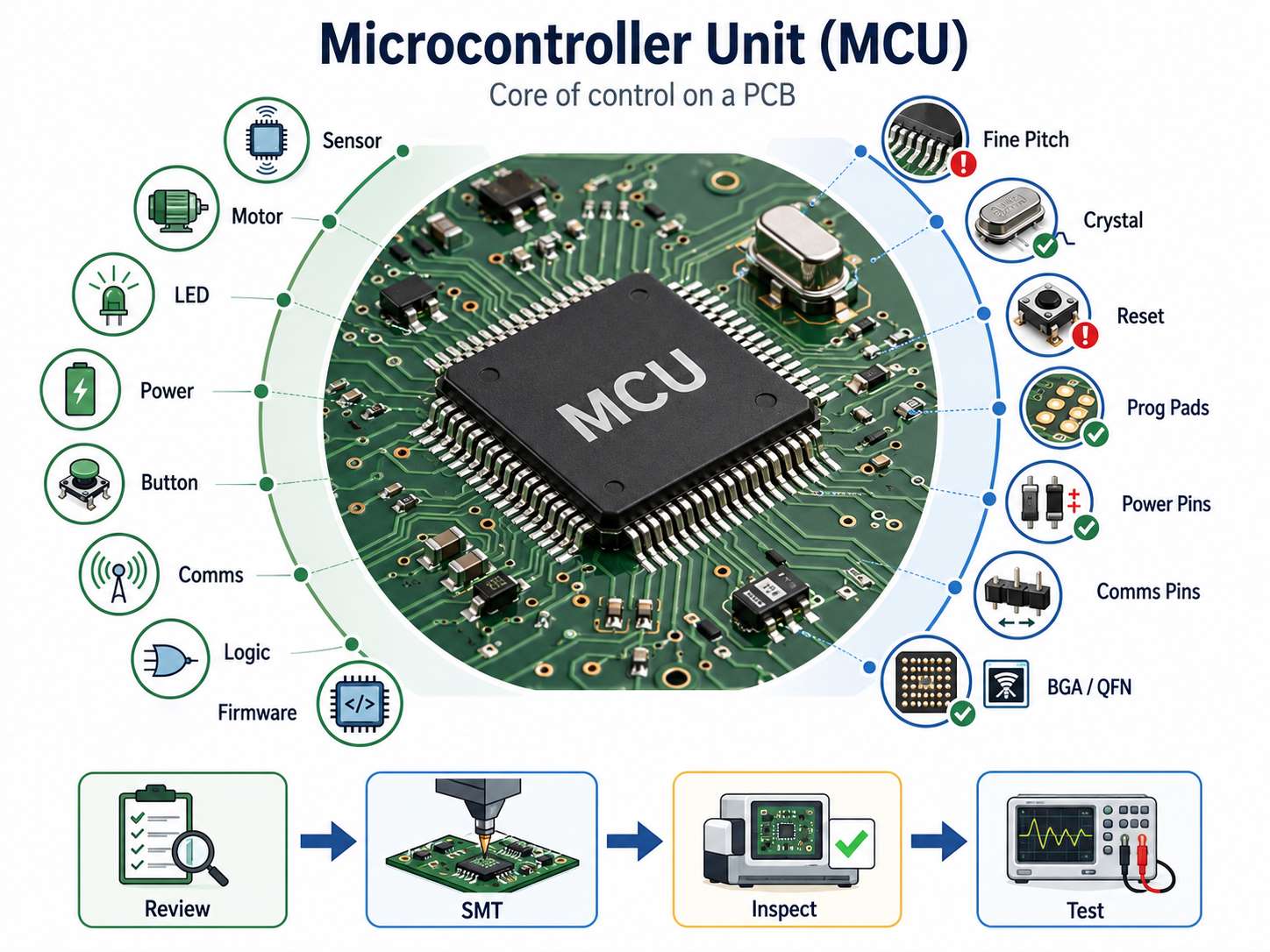
In a finished product, the MCU may control:
- sensor reading
- motor or relay output
- LED or display behavior
- battery or power monitoring
- button input
- communication with another module
- safety or control logic
- firmware-based product functions
For PCB assembly, the key point is simple: if the MCU area has a placement, soldering, power, reset, clock, or programming issue, the whole board may fail even when the rest of the assembly looks normal.
| MCU Area | Manufacturing Concern |
|---|---|
| Fine-pitch pins | Bridging, insufficient solder, alignment |
| Crystal circuit | Placement, cleanliness, stable oscillation |
| Reset circuit | Polarity, resistor/capacitor values |
| Programming pads | Accessibility after assembly |
| Power pins | Decoupling, soldering, voltage test |
| Communication pins | Connector direction, test access |
| BGA/QFN packages | AOI/X-Ray planning when needed |
This is why MCU boards need more than standard soldering. They need file review, SMT process control, inspection, and test planning before production starts.
Microcontroller Unit vs Microprocessor in PCB Projects
A microcontroller unit and a microprocessor are different in both product function and PCB manufacturing complexity.
- A microcontroller unit is usually used for embedded control. It often includes memory and peripherals inside one chip, so the surrounding circuit can be more compact.
- A microprocessor usually needs more external support, such as external memory, power management, high-speed interfaces, and more complex routing. These boards often require stronger stackup planning, impedance control, and thermal review.
| Item | Microcontroller Unit | Microprocessor |
|---|---|---|
| Main role | Embedded control | Higher computing power |
| External circuits | Usually fewer | Usually more |
| PCB complexity | Low to high, depending on package | Often higher |
| Common products | Sensors, controllers, IoT modules | Gateways, computers, advanced modules |
| PCBA focus | SMT accuracy, programming, test | Stackup, memory, high-speed, thermal |
EBest Circuit does not replace the customer’s electronic design team. The MCU model, circuit architecture, and firmware logic should come from the customer’s design side. Our role is to review whether the files, BOM, PCB structure, assembly notes, programming access, and test requirements can be produced reliably.
Key Circuits Around a Microcontroller Unit PCB
A microcontroller unit rarely works alone. The circuits around it often decide whether the board can start, run, communicate, and pass testing.
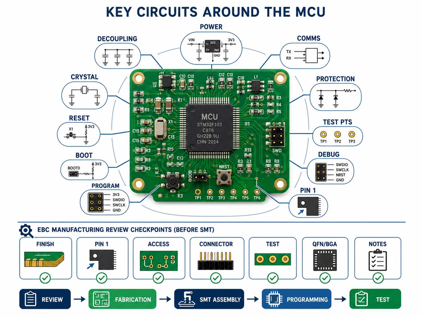
Important MCU-related areas include:
- voltage regulator and power input
- decoupling capacitors
- crystal or oscillator circuit
- reset circuit
- boot mode pins
- programming interface
- communication connectors
- protection components
- test points
- debug header
- polarity marks and Pin 1 marks
Before SMT, EBest Circuit reviews these areas from the manufacturing side.
Typical review questions include:
- Can the MCU package be assembled with the selected PCB finish?
- Are Pin 1 and polarity marks clear enough for SMT inspection?
- Are programming pads still accessible after assembly?
- Are connectors positioned correctly for the test fixture or cable?
- Are test points available for power, reset, and communication checks?
- Are QFN/BGA packages planned with the right inspection method?
- Are customer notes about firmware, label, packing, or testing included in the production package?
These checks do not change the customer’s circuit design. They help make sure the approved design can move through PCB fabrication, SMT, programming, and test without avoidable surprises.
Power Supply Unit for Microcontroller Stability
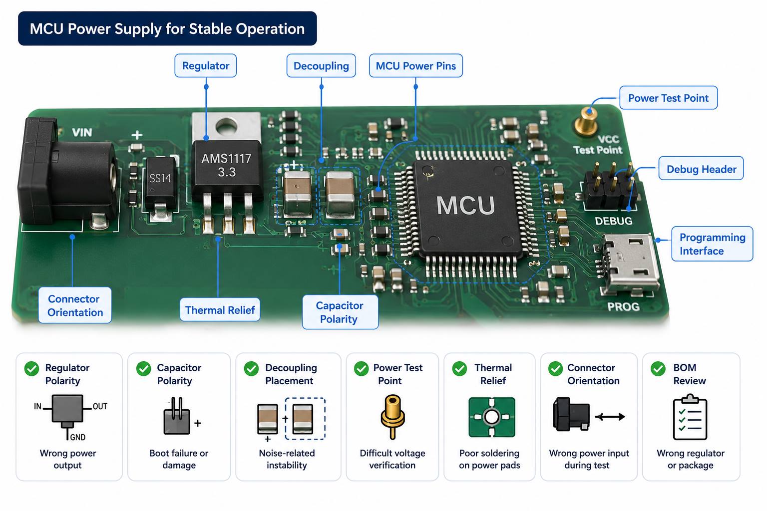
The power supply unit for microcontroller stability is one of the first areas to check in an MCU-based PCBA.
A board may look perfect after assembly but still fail if the MCU receives unstable voltage, poor decoupling, wrong polarity, excessive noise, or weak soldering around the power circuit.
For MCU PCBA projects, useful production checks include:
| Checkpoint | What It Helps Prevent |
|---|---|
| Regulator polarity | Wrong power output |
| Capacitor polarity | Boot failure or damage |
| Decoupling placement | Noise-related instability |
| Power test point | Difficult voltage verification |
| Thermal relief | Poor soldering on power pads |
| Connector orientation | Wrong power input during test |
| BOM review | Wrong voltage regulator or package |
This is especially important for industrial modules, battery-powered products, IoT devices, and control boards that must start reliably after shipment.
MCU PCB Layout Checks Before Manufacturing
MCU PCB layout checks should focus on manufacturability and assembly readiness, not on replacing the customer’s electronic design work.
EBest Circuit can review:
- minimum line/space around MCU pins
- solder mask openings
- silkscreen clearance
- Pin 1 marking
- test point access
- programming pad access
- via-in-pad risk
- BGA/QFN soldering risk
- connector orientation
- board thickness and panelization
- impedance notes if high-speed interfaces are involved
EBest Circuit’s FR4 PCB manufacturing capability covers common 1-10 layer projects, while higher-layer or more complex MCU boards can be reviewed according to stackup, copper thickness, material, and process requirements. Fine line capability also depends on copper thickness. For example, 1oz copper allows finer routing than heavier copper, while 2oz or 3oz copper may need wider line spacing.
This matters because MCU boards often place fine-pitch ICs, connectors, power circuits, programming pads, and test points into a compact PCB area. The practical goal is not only to fabricate the board, but to make sure it can be assembled, inspected, programmed, and tested without avoidable delays.
SMT Assembly Risks for Microcontroller Unit Boards
MCU boards often look simple until they reach SMT. The risk usually comes from details: fine-pitch packages, small passives, crystals, connectors, polarity-sensitive parts, and programming access.
EBest Circuit’s SMT process can include:
- PCB baking when needed
- solder paste printing
- SPI inspection
- pick and place
- reflow soldering
- post-reflow inspection
- AOI
- X-Ray for BGA when required
- hand soldering for selected parts
- cleaning
- programming
- testing
- labeling
- depaneling
- packing
Key risks we check before and after SMT:
- MCU Pin 1 direction
- IC polarity
- connector orientation
- crystal soldering
- solder bridging on fine-pitch pins
- insufficient solder on QFN pads
- BGA solder quality when used
- flux residue near connectors
- programming pad access
- packing method after assembly
For MCU boards, “small quantity” does not mean “low risk.” One prototype board still needs the same process discipline if it will be used for debugging, customer approval, or pilot production.
Programming and Testing Microcontroller Unit PCBAs
Some MCU PCBAs require firmware programming after SMT assembly. EBest Circuit can support programming when the customer provides the required firmware and instructions.
A clear programming package should include:
| Customer File or Note | Why It Matters |
|---|---|
| Firmware file | Prevents version confusion |
| Programming method | Defines tool or interface |
| Test procedure | Confirms pass/fail standard |
| Fixture notes | Avoids access problems |
| Label requirement | Supports version control |
| Packing note | Protects programmed boards |
Programming should be planned before SMT starts. If the programming pads are blocked by components, if the fixture cannot contact the board, or if firmware version control is unclear, the project may be delayed at the last stage.
For related details, you can also refer to EBest Circuit’s guide on how to program a PCB.
Microcontroller Board Assembly for Industrial and IoT Products
Microcontroller board assembly is common in industrial and IoT products because MCUs are practical for sensing, control, communication, and low-power operation.
Typical products include:
- industrial monitoring boards
- smart sensor modules
- IoT gateways
- power control boards
- medical device sub-assemblies
- automotive control modules
- wireless communication devices
- test equipment boards
- motor control modules
These products often need more than soldering. They may need component sourcing, test point review, firmware loading, functional test coordination, packaging control, and traceability.
EBest Circuit has worked in PCB and PCBA manufacturing since 2006 and serves customers across more than 40 countries and regions. For MCU-based projects exported to markets such as the USA, Germany, and Israel, stable documentation, process control, and communication are often just as important as board price.
Microcontroller Unit PCBA Case Study
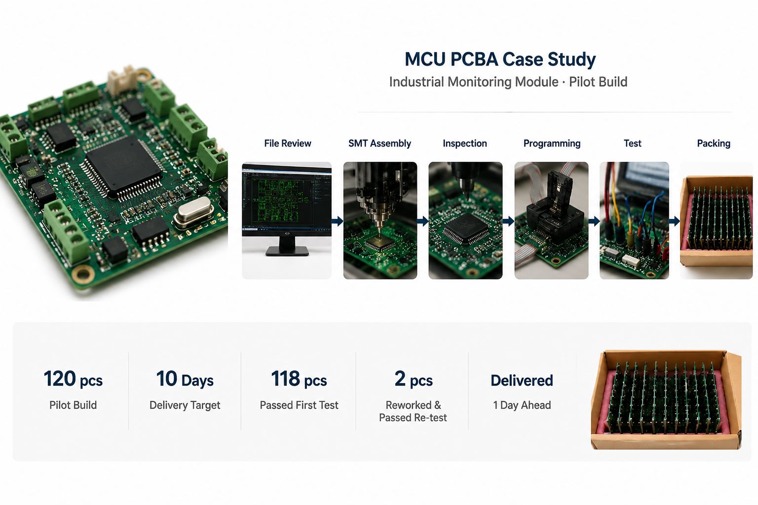
A German customer needed a pilot build of MCU-based PCBAs for an industrial monitoring module. The boards were used for engineering validation before the customer released a larger small-batch order.
Project profile
- Customer region: Germany
- Application: Industrial monitoring module
- Quantity: 120 pcs pilot build
- PCB type: 4-layer FR4 PCB
- Material: High-Tg FR4
- Surface finish: ENIG
- Assembly: SMT + connector assembly
- MCU package: Fine-pitch microcontroller
- Requirements: Firmware programming, basic functional test, individual packing
- Delivery target: 10 working days after production file confirmation
Customer concerns
- The MCU had to boot correctly after programming.
- Connector orientation had to match the customer’s test fixture.
- The crystal and power circuit needed stable soldering.
- The customer needed production feedback before moving to the next batch.
- The boards had to arrive clean and ready for validation.
EBest Circuit solution
- Reviewed Gerber, BOM, CPL, assembly drawing, and programming notes together.
- Checked MCU Pin 1, connector direction, polarity marks, and programming access before SMT.
- Confirmed panelization for stable printing, placement, AOI, and depaneling.
- Used SPI after solder paste printing and AOI after reflow.
- Added manual inspection around connectors, crystal area, and programming pads.
- Programmed the boards with customer-provided firmware.
- Followed the customer’s functional test steps before packing.
- Packed each board separately to reduce connector and component damage during shipment.
Output result
- 120 pcs assembled and programmed
- Delivered 1 day ahead of the requested schedule
- 118 pcs passed first functional test
- 2 pcs were held for connector solder touch-up and passed re-test before shipment
- Final shipped quantity: 120 pcs
- Test and production feedback were sent to the customer before the next build discussion
For this project, the value was not only “SMT assembly.” The value was keeping the MCU-related risks visible from file review to final delivery: package direction, programming access, connector orientation, soldering quality, test flow, and packing.
That is the kind of support engineers need when an MCU board must move from prototype validation to repeatable production.
Why Choose EBest Circuit for MCU PCB Assembly Projects?
MCU PCB assembly becomes risky when PCB fabrication, BOM sourcing, SMT, programming, testing, and packing are handled as separate tasks. EBest Circuit keeps these steps under one workflow, so the important details do not disappear between suppliers, departments, or production stages.
Before SMT
- Gerber, BOM, CPL, and assembly drawings are reviewed together.
- MCU Pin 1, polarity, connector direction, and programming access are checked.
- Component sourcing risks are confirmed before the SMT schedule is fixed.
- Panelization is reviewed for printing, placement, AOI, and depaneling.
- Firmware, test, label, and packing notes are added to the production file.
During assembly
- SPI checks solder paste printing before placement.
- AOI checks soldering and component placement after reflow.
- X-Ray can be arranged for BGA or hidden solder joints when required.
- Connector areas, crystal circuits, programming pads, and polarity-sensitive parts receive extra attention.
- Cleaning, labeling, depaneling, and packing are handled according to project notes.
Before shipment
- Programming can be performed with customer-provided firmware.
- Functional test steps can be followed according to customer instructions.
- Failed units can be held, checked, reworked, and re-tested before delivery.
- Individual packing can be arranged for assembled boards.
- Production feedback can be shared before the next prototype or pilot build.
EBest Circuit has worked in PCB and PCBA manufacturing since 2006. The company supports PCB fabrication, component sourcing, SMT assembly, testing, and small-batch production under one workflow. Quality support includes ISO9001, ISO13485, IATF16949, AS9100D, RoHS, REACH, and UL-related documentation.
The team structure also matters for MCU projects. Many engineers, quality managers, production leaders, and sales members at EBest Circuit have worked in the company for more than 10 years. This helps keep communication stable when a prototype needs quick judgment on BOM risk, SMT access, programming notes, test results, or delivery changes.
For an MCU board, the order quantity may be small, but the decision behind it is not small. A failed pilot build can delay debugging, customer approval, and the next production stage. EBest Circuit helps keep the manufacturing, assembly, programming, and testing details connected before the board reaches the customer’s bench.
FAQs about Microcontroller Unit PCB Assembly
1. What is a microcontroller unit?
A microcontroller unit is an integrated circuit that includes a processor, memory, I/O pins, and control functions. It is used to control electronic products and embedded systems.
2. Is a microcontroller unit the same as a microprocessor?
No. A microcontroller usually includes memory and peripherals inside one chip, while a microprocessor often needs more external memory, power, and support circuits.
3. Can EBest Circuit help choose the microcontroller?
EBest Circuit can review BOM availability, package assembly risk, and manufacturing concerns. The final MCU selection should come from the customer’s electronic design team.
4. Can EBest Circuit program microcontroller PCBAs?
Yes, when the customer provides the firmware file, programming method, fixture requirement, and test standard. EBest Circuit supports programming based on customer-provided instructions.
5. What files are needed for MCU PCB assembly?
Common files include Gerber or ODB++, BOM, CPL, assembly drawing, programming file, test instruction, and packing requirement.
6. What should be checked before producing an MCU PCB?
Important checks include power stability, programming access, test points, connector orientation, fine-pitch pads, solder mask openings, polarity marks, and assembly notes.
If your microcontroller unit project is ready for prototype or small-batch production, EBest Circuit can help review the PCB fabrication, BOM, SMT, programming, and testing path before production starts. Send your Gerber files, BOM, CPL, firmware/programming notes, or assembly questions to sales@bestpcbs.com. Our engineering team will help check the details that often decide whether the first build moves smoothly into real validation.
You may also like


Tags: MCU PCB assembly, microcontroller board assembly, microcontroller unit